EP1279783A1 - Schliessvorrichtung - Google Patents
Schliessvorrichtung Download PDFInfo
- Publication number
- EP1279783A1 EP1279783A1 EP02014763A EP02014763A EP1279783A1 EP 1279783 A1 EP1279783 A1 EP 1279783A1 EP 02014763 A EP02014763 A EP 02014763A EP 02014763 A EP02014763 A EP 02014763A EP 1279783 A1 EP1279783 A1 EP 1279783A1
- Authority
- EP
- European Patent Office
- Prior art keywords
- rotating part
- locking device
- transmission
- transmission part
- lock
- Prior art date
- Legal status (The legal status is an assumption and is not a legal conclusion. Google has not performed a legal analysis and makes no representation as to the accuracy of the status listed.)
- Granted
Links
- 230000005540 biological transmission Effects 0.000 claims abstract description 69
- 230000033001 locomotion Effects 0.000 claims abstract description 33
- 230000001419 dependent effect Effects 0.000 description 3
- 238000004519 manufacturing process Methods 0.000 description 3
- 238000000034 method Methods 0.000 description 2
- 230000001154 acute effect Effects 0.000 description 1
- UQMRAFJOBWOFNS-UHFFFAOYSA-N butyl 2-(2,4-dichlorophenoxy)acetate Chemical compound CCCCOC(=O)COC1=CC=C(Cl)C=C1Cl UQMRAFJOBWOFNS-UHFFFAOYSA-N 0.000 description 1
- 230000000694 effects Effects 0.000 description 1
- 230000002349 favourable effect Effects 0.000 description 1
- 230000000977 initiatory effect Effects 0.000 description 1
- 238000002347 injection Methods 0.000 description 1
- 239000007924 injection Substances 0.000 description 1
- 238000001746 injection moulding Methods 0.000 description 1
- 239000002184 metal Substances 0.000 description 1
- 230000000717 retained effect Effects 0.000 description 1
- 239000000243 solution Substances 0.000 description 1
Images



Classifications
-
- E—FIXED CONSTRUCTIONS
- E05—LOCKS; KEYS; WINDOW OR DOOR FITTINGS; SAFES
- E05B—LOCKS; ACCESSORIES THEREFOR; HANDCUFFS
- E05B17/00—Accessories in connection with locks
- E05B17/04—Devices for coupling the turning cylinder of a single or a double cylinder lock with the bolt operating member
- E05B17/041—Coupling device with a shaft projecting axially rearwardly from the cylinder, e.g. affording a degree of universal motion to compensate for misalignment
-
- E—FIXED CONSTRUCTIONS
- E05—LOCKS; KEYS; WINDOW OR DOOR FITTINGS; SAFES
- E05B—LOCKS; ACCESSORIES THEREFOR; HANDCUFFS
- E05B17/00—Accessories in connection with locks
- E05B17/04—Devices for coupling the turning cylinder of a single or a double cylinder lock with the bolt operating member
-
- E—FIXED CONSTRUCTIONS
- E05—LOCKS; KEYS; WINDOW OR DOOR FITTINGS; SAFES
- E05B—LOCKS; ACCESSORIES THEREFOR; HANDCUFFS
- E05B53/00—Operation or control of locks by mechanical transmissions, e.g. from a distance
-
- E—FIXED CONSTRUCTIONS
- E05—LOCKS; KEYS; WINDOW OR DOOR FITTINGS; SAFES
- E05B—LOCKS; ACCESSORIES THEREFOR; HANDCUFFS
- E05B85/00—Details of vehicle locks not provided for in groups E05B77/00 - E05B83/00
- E05B85/06—Lock cylinder arrangements
-
- E—FIXED CONSTRUCTIONS
- E05—LOCKS; KEYS; WINDOW OR DOOR FITTINGS; SAFES
- E05B—LOCKS; ACCESSORIES THEREFOR; HANDCUFFS
- E05B83/00—Vehicle locks specially adapted for particular types of wing or vehicle
- E05B83/36—Locks for passenger or like doors
Definitions
- the invention relates to a locking device, in particular for motor vehicle doors with a lock cylinder to be actuated by a key, with a lock mechanism for locking and unlocking the door and with a transmission part between the lock cylinder and lock mechanism, in this case a rotating part with the lock cylinder and with the lock mechanism connected to which the transmission part attacks.
- a locking device in particular for motor vehicle doors with a lock cylinder to be actuated by a key, with a lock mechanism for locking and unlocking the door and with a transmission part between the lock cylinder and lock mechanism, in this case a rotating part with the lock cylinder and with the lock mechanism connected to which the transmission part attacks.
- a double Bowden cable is provided between the two rotating parts, through which rotation of the lock mechanism occurs when the cylinder rotates.
- the exact manufacture and assembly as well as the adjustment of the deflection rollers for the Bowden cable is complex.
- the object of the present invention is to design a locking device of the type mentioned at the outset in such a way that it is easy to use, but in particular it is economical to manufacture and install.
- the transmission part is rod-shaped that both the Locking cylinder associated rotating part and the rotating mechanism associated with the lock mechanism is designed in a crank-like manner with an axis of rotation and with at least one crank arm that the rod-like transmission part is arranged on the crank pin; here, when the rotating part of the locking cylinder rotates, the transmission part performs both a pivoting movement and a translational movement on, in which the rotating part of the lock mechanism is also movable.
- the design and assembly can be carried out inexpensively, since a mounting is reliably ensured by attaching the transmission rod to the rotating part.
- the production itself is also easy because on the one hand the rotating part can be easily coupled with the lock cylinder, and on the other hand easily with the lock mechanism.
- the rod-like transmission part also allows the distance between the locking device and the lock mechanism to be kept exactly. In order to obtain a precise starting and resetting arrangement during the closing or opening process, it is recommended that at least one of the rotating parts of the locking cylinder and / or locking mechanism is loaded with a spring which turns the rotating part back into an initial position when released.
- the transmission part is particularly advisable to provide the transmission part with a slot-like opening in which the crank arm of the one rotating part engages.
- a rotation angle of + 90 ° degrees for the locking cylinder it is possible, for example, to achieve a rotation angle of + 90 ° degrees for the locking cylinder, but nevertheless a secure closure or opening can be achieved by this measure when the rotary movement of the one rotating part is initiated.
- the rotating part has a double bearing, in this case the transmission part is arranged between the two bearing points.
- This double bearing point achieves an exact rotatability of the turned part, moreover an exact guidance of the transmission rod, this also ensures that any forces acting on the transmission rod are safely intercepted.
- the rotating part has two rod-like transmission parts, in this case a crank pin carries the one transmission part and a second crank pin directed in exactly the opposite direction carries the second transmission part, the two crank pins on the rotating part being at an angular distance apart in the axial direction.
- This arrangement allows the second rotating part to be carried as soon as the first rotary movement is initiated.
- the second rotary part follows the first rotary part. It is particularly favorable here that the torque transmission is hardly dependent on the angle function, since the starting pivot point is selected such that a uniform transmission is possible, since the lever arm with which the rod is moved with respect to the rotating part hardly changes with regard to the force transmission.
- crank pins are arranged on an anchor-like intermediate piece.
- This anchor-like intermediate piece is arranged in a U-shape, the transmission rod then being arranged on the U-leg on one side, while the second transmission part is arranged on the other leg on the other side.
- the transmission rod comprises a bend in its longitudinal direction.
- the invention can also be used when the axes of the lock mechanism and the lock cylinder are not parallel to each other, but intersect, which enables precise alignment, on the one hand to be able to move the lock mechanism when the lock cylinder rotates, even if it does is not parallel to the first axis.
- the lock cylinder axis and the lock axis must form one plane.
- the size of the bend allows the slope with which the two axes run to be adjusted or aligned from the outset.
- the bend is advantageously in the region of the elongated hole recess of the transmission part.
- the crank pin slides in the slot opening and can thus move the transmission rod at an angle to the lock cylinder axis during a translational movement.
- a simple latching movement already ensures that the rod is fastened between the two rotating parts, in this case it is particularly advantageous if a spherical section is provided as a crank pin for mounting the transmission part on the rotating part, on which the transmission rod can be clipped on with a corresponding cup-shaped recess. Again, a secure mounting and easy assembly is guaranteed.
- a pivoting rotary lever is arranged on the rotating part of the lock mechanism carries the second crank pin for the transmission part, here the pivot lever is both rotatable and tiltable, stops being provided on the rotating part to limit the rotational movement.
- the pivoting rotary lever to carry out a movement before the actual rotating part of the lock mechanism carries out the rotating movement.
- the direction in which the rotating part is to rotate later is predetermined by pivoting the rotating part, the rotating part of the lock mechanism with the locking cylinder being rotatable as soon as the pivoting rotary lever comes against the stops.
- the pivoting lever shortens the effective length between the two rotating parts in such a way that it is ensured that the rotating part of the lock mechanism is only moved in the direction emphasized by the rotary movement of the locking cylinder.
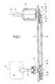
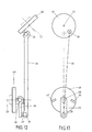
- the locking device is shown schematically.
- a mounting wall 31 is provided.
- the locking cylinder 20 with its rotating part 24 is fixed to this fastening wall.
- the locking cylinder can be rotated by means of a key 21. As it moves, it also rotates the rotating part 24.
- this rotating part is designed like a crank.
- the axis of rotation 25 of the rotating part 24 coincides with the lock cylinder axis 32.
- the rotating part 24 comprises a turntable 48 which merges into a crank arm 36 on which the crank pin 26 is provided.
- This crank pin 26 engages in a transmission part 30, so that when the rotary part rotates, the transmission part swivels.
- the lower rotating part 27 is also mounted in the housing wall 31. It is connected via a transmission paddle 23 to the lock mechanism 22 in such a way that when the rotating part 27 rotates, the Transfer paddle also rotates and moves the bolt or latch of the lock.
- the transfer paddle compensates for any axis offsets between the axis of rotation 28 and the axis 33 of the lock device by the type of mounting of the transfer paddle.
- the rotary movement is transmitted to the lock mechanism 22 in any case.
- the rotating part 27 comprises a turntable 49 which merges into a crank arm 36, in which the crank axis 29 engages, which is arranged on the transmission rod 30. It should also be mentioned here that the rotating part 27 or the rotating part 24 is loaded with a spring (not shown), which makes it possible to reset the position shown after each movement. This spring allows the rotating part to be turned on both sides. Nevertheless, the starting position can be set exactly.
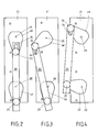
- FIG. 2 shows a front view of the schematically illustrated locking device. It is in the starting position.
- the rotation of the locking cylinder 20 causes the upper turntable 48 to move, the crank axis 26 sliding in the slot-like recess 34 up to the upper end.
- the lower rotary part 27 is then also moved via the rod 30 and can thus actuate the lock mechanism.
- slot-like recess 34 means that the torque transmission for opening or closing the lock is only slightly dependent on the angle of rotation, since the first section of the rotary movement takes place without the lower rotary part.
- the rotational advance as shown in FIG. 3, is approximately 45 ° degrees.
- the course of rotation is designed in such a way that when the transmission part is inclined and the end of the rotational advance, the transmission part seen in side view no longer covers the axis of rotation.
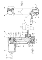
- the locking device consists of two transmission rods 30.
- the locking device itself is shown schematically in a housing 35.
- This housing has a receiving chamber for the lock cylinder 20.
- the upper rotating part is supported at both ends (as a double bearing).
- a crank arm 36 In the center of the rotating part there is a crank arm 36, radially to the axis of rotation, on which the crank pin 26 is provided, in this case the crank pin is present twice, namely on the one hand pointing towards the locking cylinder and on the other hand precisely on the other side.
- the two crank pins are offset from one another by a certain angular amount in the axial direction of the locking cylinder.
- the crank pin is provided with a knob-like part 39.
- a shell 40 of the transmission rod is clipped onto this knob 39.
- the lower rotating part is approximately U-shaped. It is also rotatably supported at its two ends in the housing, in which case one end carries the transfer paddle 23.
- the lower rotating part 27 is shown with a U-shaped rotary section 41, the ends of the legs carrying the axis of rotation, while the ends provided on the central web Each leg wear a lateral arm-like arm 42, which carries the crank pin 29 in the form of a rotary knob 39.
- the return spring 37 is shown in FIG. 5. This spring is designed as a wing spring and has the effect that the position shown in FIG. 5 or 6 is retained when the key 21 is released or adjusts itself automatically.
- the position according to FIG. 9 is then adopted, in this case the position according to FIG. 8 serves to release the lock part of the lock device, while the position according to FIG. 9 includes the locking of the lock of the lock device.
- the housing 35 and the transmission rods 30 have a bend 43, the bend here being perpendicular to the axis of rotation of the lower rotating part or of the U-shaped rotating section.
- the upper two rod parts are moved downward and at the same time the rotary movement of the lower rotary section 41 is initiated, so that the rods exert a pivoting movement with respect to the upper fastening.
- the slot-like recess 44 ensures that when the locking cylinder is rotated by a first amount, the lower rotating part remains in the position shown here. Only when the knob 39 is at the upper end of the slot-like recess 34 is the rotary movement and thus the opening or closing of the lock initiated. It is important that the first part of the rotary movement of the upper rotating part runs without rotating the lower part, that the rod swings either to the left or to the right depending on how it is rotated, so that with a further movement the lock device into yours The closed or open position can be transferred, as the embodiment according to FIGS. 2, 3 and 4 shows.
- the rotating part 24 is provided with a return spring 37, which makes it possible for the starting position to be set after each opening operation and release of the key.
- a locking device is shown schematically, in which in turn the axis of the locking cylinder and the axis of the locking device are arranged at an angle to one another.
- the transmission rod 30 is fastened in a clip-like manner to the upper rotating part 24.
- a knob-like fastening point 50 is provided in the center of the lower rotating part 27.
- a pivot lever is attached to this knob-like attachment point 45 clipped on. This pivot lever is both rotatable and pivoted away from the rotating part.
- the transmission rod is pivoted, as a result of which either the pivot lever 45 would have to perform a rotational movement or else it would pivot away from the lower rotating part, as shown in FIG. 14.
- the pivoting projection With a further rotation of the upper turntable 48, the pivoting projection finally strikes against stops 46 and 47 and cf. FIG. 15, and can then also move the lower rotating part.
- the swivel lever ensures that when the rotary movement is initiated, the lower rotary part is carried along exactly from FIG. 12.
- the starting point can in turn be set automatically by a spring (not shown) when the locking device is released. With a movement then in the clockwise direction, the lower rotating part would also rotate in the clockwise direction, but in this case the pivoting movement of the pivoting insert would initially occur until the pivoting lever would finally hit the stop 47.
- the illustrated embodiments are implementations of the invention, for example. This is not limited to this. Rather, various changes and applications are still possible.
- the return spring could be provided both on the upper and on the lower rotating part.
- the transmission part can consist of a sheet metal strip or of a plastic injection molded part.
- the invention also consists in the fact that the case of a rod solution can be used to rotate the cylinder lock by ⁇ 90 °.
Landscapes
- Lock And Its Accessories (AREA)
- Refuge Islands, Traffic Blockers, Or Guard Fence (AREA)
Abstract
Description
- Die Erfindung betrifft eine Schließvorrichtung, insbesondere für Kraftfahrzeugtüren mit einem durch einen Schlüssel zu betätigenden Schließzylinder, mit einem Schlossmechanismus zur Ver- und Entriegelung der Tür und mit einem Übertragungsteil zwischen Schließzylinder und Schlossmechanismus, hierbei ist drehfest mit dem Schließzylinder und mit dem Schlossmechanismus jeweils ein Drehteil verbunden, an dem das Übertragungsteil angreift. Derartige Ausführungen sind bereits bekannt. Zwischen den beiden Drehteilen ist ein doppelter Bowdenzug vorgesehen, durch den bei Drehung des Zylinders eine Drehung des Schlossmechanismus eintritt. Aufwendig ist die genaue Fertigung und die Montage sowie die Verstellung der Umlenkrollen für den Bowdenzug.
- Aufgabe der vorliegenden Erfindung ist, eine Schließvorrichtung der eingangs genannten Art so zu gestalten, dass sie einfach zu bedienen, insbesondere aber kostensparend herzustellen und einzubauen ist.
- Diese Aufgabe wird erfindungsgemäß dadurch erreicht, dass das Übertragungsteil stangenartig ausgebildet ist, dass sowohl das dem Schließzylinder zugeordnete Drehteil als auch das dem Schlossmechanismus zugeordnete Drehteil kurbelartig mit einer Drehachse und mit wenigstens einem Kurbelarm ausgebildet ist, dass an dem Kurbelzapfen das stangenartige Übertragungsteil angeordnet ist, hierbei führt bei einer Drehbewegung des Drehteiles des Schließzylinders das Übertragungsteil sowohl eine Schwenkbewegung als auch eine Translationsbewegung auf, bei der das Drehteil des Schlossmechanismus mit bewegbar ist. Durch eine solche Ausbildung kann genau der Abstand zwischen Schließvorrichtung und Schlossmechanismus überbrückt werden, darüber hinaus ist die Ausbildung und Montage kostengünstig durchzuführen, da durch die Anbringung der Übertragungsstange an das Drehteil sicher eine Halterung gewährleistet wird. Die Herstellung selber ist auch einfach, weil das Drehteil einerseits leicht mit dem Schließzylinder ankuppelbar ist, andererseits leicht mit dem Schlossmechanismus. Das stangenartige Übertragungsteil erlaubt darüber hinaus den Abstand zwischen Schließvorrichtung und Schlossmechanismus genau einzuhalten. Um bei dem Schließ- oder Öffnungsvorgang eine genaue Ausgangs- und eine Rückstellanordnung zu erhalten, empfiehlt es sich, dass wenigstens eines der Drehteile vom Schließzylinder und/oder Schlossmechanismus mit einer Feder belastet ist, die das Drehteil bei Freigabe in eine Ausgangslage zurückdreht.
- Besonders empfehlenswert ist es, das Übertragungsteil mit einem schlitzartigen Durchbruch zu versehen, in der der Kurbelarm des einen Drehteiles eingreift. Auf diese Weise ist es möglich, beispielsweise einen Drehwinkel von + 90° Grad des Schließzylinders zu erreichen, trotzdem kann aber durch diese Maßnahme bei Einleitung der Drehbewegung des einen Drehteiles eine sichere Schließung oder Öffnung erzielt werden.
- Bei einem besonderen Ausführungsbeispiel der Erfindung weist das Drehteil eine Doppellagerung auf, hierbei ist zwischen den beiden Lagerstellen das Übertragungsteil angeordnet. Über diese Doppellagerstelle ist eine genaue Drehbarkeit des Drehteiles erreicht, darüber hinaus eine genaue Führung der Übertragungsstange, hierbei wird weiterhin sichergestellt, dass etwaige auf die Übertragungsstange wirkende Kräfte sicher abgefangen werden.
- Bei einem besonderen Ausführungsbeispiel der Erfindung weist das Drehteil zwei stangenartige Übertragungsteile auf, hierbei trägt ein Kurbelzapfen das eine Übertragungsteil und ein zweiter genau entgegengesetzt gerichteter Kurbelzapfen das zweite Übertragungsteil, wobei in Achsrichtung gesehen die beiden Kurbelzapfen an dem Drehteil um einen Winkelbetrag auseinanderliegen. Diese Anordnung gestattet, dass sofort bei Einleitung der ersten Drehbewegung das zweite Drehteil mitgeführt wird. Bei Einleitung der anderen Drehbewegung von einer Ausgangslage aus folgt dann das zweite Drehteil dem ersten Drehteil. Besonders günstig ist hierbei, dass die Drehmomentübertragung kaum winkelfunktionsabhängig ist, da der Ausgangsdrehpunkt so gewählt ist, dass eine gleichförmige Übertragung möglich ist, da der Hebelarm, mit dem die Stange bezüglich des Drehteiles bewegt wird, sich hinsichtlich der Kraftübertragung kaum verändert. Bei einer besonders einfachen Gestaltung sind die Kurbelzapfen an einem ankerartigen Zwischenstück angeordnet. Dieses ankerartige Zwischenstück ist U-förmig angeordnet, wobei dann an dem U-Schenkel nach der einen Seite die Übertragungsstange angeordnet ist, während an dem anderen Schenkel an der anderen Seite das zweite Übertragungsteil.
- Wiederum wird gewährleistet, dass eine sichere Verstellung, die nur geringfügig drehmomentabhängig ist, geschaffen wird, zugleich lassen sich solche Teile leicht im Spritzgussverfahren herstellen.
- Bei einem besonderen Ausführungsbeispiel umfasst die Übertragungsstange in ihrer Längsrichtung eine Abbiegung. Die Erfindung kann dann auch verwendet werden, wenn die Achsen des Schlossmechanismus und des Schließzylinders nicht parallel zueinander liegen, sondern sich schneiden, wodurch eine genaue Ausrichtung möglich ist, um einerseits bei der Drehung des Schließzylinders auch den Schlossmechanismus bewegen zu können, selbst, wenn dieser nicht parallel zu der ersten Achse liegt. Dabei müssen die Schließzylinderachse und die Schlossachse eine Ebene bilden.
- Die Größe der Abbiegung erlaubt die Schräge, mit der die beiden Achsen verlaufen, einzustellen bzw. von vornherein auszurichten.
- Vorteilhafterweise liegt die Abbiegung im Bereich der Langlochausnehmung des Übertragungsteiles. Durch diese Maßnahme gleitet der Kurbelzapfen in der Langlochausnehmung und kann somit bei einer Translationsbewegung die Übertragungsstange in einem Winkel zur Schließzylinderachse bewegen. Um eine schnelle Montage zwischen Kurbelzapfen und stangenartigem Übertragungsteil zu erhalten, empfiehlt es sich, das Übertragungsteil mit einer Rastverbindung an dem Drehteil festzulegen. Durch eine einfache Rastbewegung ist bereits die Befestigung der Stange zwischen den beiden Drehteilen gewährleistet, hierbei ist es besonders günstig, wenn zur Lagerung des Übertragungsteiles am Drehteil ein kugelförmiger Abschnitt als Kurbelzapfen vorgesehen ist, auf dem die Übertragungsstange mit einer entsprechenden schalenförmigen Ausnehmung aufklippsbar ist. Wiederum ist eine sichere Halterung und leichte Montage gewährleistet.
- Bei einem besonderen Ausführungsbeispiel der Erfindung ist an dem Drehteil des Schlossmechanismus ein Schwenkdrehhebel angeordnet, der den zweiten Kurbelzapfen für das Übertragungsteil trägt, hierbei ist der Schwenkhebel sowohl drehbar als auch kippbar angeordnet, wobei zur Begrenzung der Drehbewegung Anschläge am Drehteil vorgesehen ist. Eine solche Ausbildung gestattet, dass der Schwenkdrehhebel eine Bewegung ausführen kann, bevor das eigentliche Drehteil des Schlossmechanismus die Drehbewegung ausführt. Durch Schwenkung des Drehteiles wird die Richtung vorbestimmt, mit der sich das Drehteil später drehen soll, wobei, sobald der Schwenkdrehhebel gegen die Anschläge kommt, das Drehteil des Schlossmechanismus mit dem Schließzylinder drehbar ist. Durch den Schwenkdrehhebel wird bei einer Drehbewegung die wirksame Länge zwischen den beiden Drehteilen derartig verkürzt, dass sichergestellt ist, dass das Drehteil des Schlossmechanismus nur in die durch die Drehbewegung des Schließzylinders hervorgehobene Richtung bewegt wird.
- Auf der Zeichnung ist der Erfindungsgegenstand in mehreren Ausführungsbeispielen dargestellt und zwar zeigen:
- Fig. 1
- in schematischer Darstellung in Seitenansicht Schließzylinder und Schlossmechanismus,
- Fig. 2 bis 4
- die einzelnen Stellungen des Übertragungsteiles,
- Fig. 5
- im Schnitt ein weitere Ausführungsbeispiel mit zwei Übertragungsstangen,
- Fig. 6
- in perspektivischer Darstellung zwei Übertragungsstangen an einer U-förmigen ankerartigen Halterung,
- Fig. 7 bis 9
- die verschiedenen Darstellungen des Übertragungsmechanismus bei zwei Übertragungsstangen,
- Fig. 10
- in Seitenansicht zwei Übertragungsstangen im Schnitt,
- Fig. 11
- im Seitenschnitt eine Übertragungsstange mit Abbiegung und Ausnehmung,
- Fig. 12 bis 15
- in schematischer Darstellung die Schließvorrichtung 19 mit einem Schwenkdrehhebel.
- Bei Ausführungsbeispiel nach Fig. 1 ist die Schließvorrichtung schematisch dargestellt. Es ist eine Befestigungswand 31 vorgesehen. An diese Befestigungswand ist der Schließzylinder 20 mit seinem Drehteil 24 festgelegt. Der Schließzylinder ist mittels eines Schlüssels 21 drehbar. Bei seiner Bewegung dreht er das Drehteil 24 mit. Dieses Drehteil ist, wie zu erkennen ist, kurbelartig ausgebildet. Die Drehachse 25 des Drehteiles 24 fällt mit der Schließzylinderachse 32 zusammen.
- Das Drehteil 24 umfasst eine Drehscheibe 48, die in einen Kurbelarm 36 übergeht, an der der Kurbelzapfen 26 vorgesehen ist. Dieser Kurbelzapfen 26 greift in ein Übertragungsteil 30, so dass bei einer Drehbewegung des Drehteiles eine Verschwenkung des Übertragungsteiles eintritt.
- Das untere Drehteil 27 ist ebenfalls in der Gehäusewand 31 gelagert. Es steht über ein Übertragungspaddel 23 mit dem Schlossmechanismus 22 derart in Verbindung, dass bei Drehung des Drehteiles 27 das Übertragungspaddel sich ebenfalls dreht und den Riegel oder die Falle der Schlosses mitbewegt.
- Es sei hier vorgetragen, dass das Übertragungspaddel etwaige Achsversetzungen zwischen Drehachse 28 sowie der Achse 33 der Schlossvorrichtung durch die Art der Lagerung des Übertragungspaddels ausgleicht. Bei Drehung des unteren Drehteiles 27 um die Drehachse 28 wird auf jeden Fall die Drehbewegung auf den Schlossmechanismus 22 übertragen.
- Das Drehteil 27 umfasst eine Drehscheibe 49, die in einen Kurbelarm 36 übergeht, in dem die Kurbelsachse 29 eingreift, die an der Übertragungsstange 30 angeordnet ist. Es sei hier noch erwähnt, dass das Drehteil 27 oder das Drehteil 24 mit einer Feder belastet ist (nicht dargestellt), die es ermöglicht, die gezeigte Stellung nach jeder Bewegung wieder einzustellen. Diese Feder erlaubt eine Drehung des Drehteiles nach beiden Seiten. Trotzdem kann genau die Ausgangslage wieder eingestellt werden.
- In Fig. 2 ist eine Vorderansicht der schematisch dargestellten Schließvorrichtung gezeigt. Sie befindet sich in der Ausgangslage. Durch Drehung des Schließzylinders 20 bewegt sich die obere Drehscheibe 48, hierbei gleitet die Kurbelachse 26 in der schlitzartigen Ausnehmung 34 bis zu dem oberen Ende. Bei einer weiteren Drehung wird dann über die Stange 30 auch das untere Drehteil 27 bewegt und kann somit den Schlossmechanismus betätigen.
- In Fig. 4 ist dargestellt, wenn der Schlossmechanismus betätigt ist. Durch die nicht dargestellte Rückstellfeder wird bei Freigabe des Schlüssels der untere Drehteil und damit der obere Drehteil in seine Ausgangsstellung bewegt.
- Es sei hier noch erwähnt, dass durch die schlitzartige Ausnehmung 34 die Drehmomentübertragung zum Öffnen oder Schließen des Schlosses nur im geringen Maße vom Drehwinkel abhängig ist, da der erste Abschnitt der Drehbewegung ohne das untere Drehteil erfolgt.
- Weiter sei noch darauf hingewiesen, dass ausgehend von Fig. 3 der obere Teil 24 um ca. 90° Grad gedreht werden muss, damit der Schließvorgang des Schlossmechanismus abgeschlossen wird, wie Fig. 4 zeigt.
- Schließlich sei erwähnt, dass der Drehvorlauf, wie Fig. 3 zeigt, etwa 45° Grad beträgt. Der Drehverlauf ist so ausgelegt, dass bei Schrägstellung des Übertragungsteiles bei Beendigung des Drehvorlaufes der Übertragungsteil in Seitenansicht gesehen, die Drehachse nicht mehr abdeckt.
- Bei der Ausführungsform nach Fig. 5 und 6 besteht die Schließvorrichtung aus zwei Übertragungsstangen 30.
- Die Schließvorrichtung selber ist schematisch dargestellt in einem Gehäuse 35 untergebracht. Dieses Gehäuse weist eine Aufnahmekammer für den Schließzylinder 20 auf. Das obere Drehteil ist an seinen beiden Enden (als Doppellagerung) gelagert. Mittig am Drehteil befindet sich radial zur Drehachse ein Kurbelarm 36, an der der Kurbelzapfen 26 vorgesehen ist, hierbei ist der Kurbelzapfen doppelt vorhanden und zwar weist er zum einen nach dem Schließzylinder hin und zum anderen genau nach der anderen Seite hin.
- Die beiden Kurbelzapfen sind, wie Fig. 6 zeigt, um einen bestimmten Winkelbetrag in Achsrichtung des Schließzylinders gesehen zueinander versetzt. Der Kurbelzapfen ist mit einem knaufartigen Teil 39 versehen. Auf diesen Knauf 39 wird eine Schale 40 der Übertragungsstange aufgeklippst.
- Das untere Drehteil ist etwa U-förmig gestaltet. Es ist auch an seinen beiden Enden im Gehäuse drehgelagert, hierbei trägt das eine Ende das Übertragungspaddel 23. Das untere Drehteil 27 ist mit einem U-förmigen Drehabschnitt 41 dargestellt, hierbei tragen die Enden des Schenkels die Drehachse, während die am Mittelsteg vorgesehenen Enden der Schenkel jeweils einen seitlichen ankerartigen Arm 42 tragen, der den Kurbelzapfen 29 in Form eines Drehknaufes 39 trägt.
- Bei einer Drehbewegung des Schließzylinders wird die eine Übertragungsstange 30 bezüglich Fig. 5 und 6 gesehen, hochbewegt, während die andere Stange 30 nach unten bewegt wird. Bei der entgegengesetzten Bewegung erfolgt die Bewegung genau umgekehrt. Wichtig ist in diesem Falle, dass auch hier die Drehmomentübertragung relativ gleichförmig ist.
- Darauf hinzuweisen ist noch, dass in Fig. 5 die Rückstellfeder 37 dargestellt ist. Diese Feder ist als Flügelfeder ausgebildet und bewirkt, dass die in Fig. 5 oder 6 dargestellte Stellung bei Freigabe des Schlüssels 21 erhalten bleibt bzw. sich selbständig einstellt.
- In Fig. 7, 8 und 9 sind die verschiedenen Stellungen des Schließmechanismus dargestellt. Bei Drehung des oberen Drehteiles 24 wird der Kurbelzapfen 26 mit den beiden Übertragungsstangen 30 mit bewegt, zugleich wird sofort bei Beginn der Bewegung auch der U-förmige Abschnitt 21 des unteren Drehteiles 27 in die in Fig. 8 dargestellte Lage bewegt.
- Bei Freigabe des Schließzylinders würde von Fig. 8 aus wiederum die Stellung nach Fig. 7 erreicht.
- Bei einer anderen Drehung im Gegenuhrzeigersinn des oberen Drehteiles 24 wird dann die Stellung nach Fig. 9 eingenommen, hierbei dient die Stellung nach Fig. 8 zur Freigabe des Schlossteiles der Schlossvorrichtung, während die Stellung nach Fig. 9 die Verriegelung des Schlosses der Schlossvorrichtung beinhaltet.
- Es sei hier bemerkt, dass diese drei Figuren nur schematisch dargestellt sind. Die genauen Lagerstellen sind fortgelassen.
- Bei dem Ausführungsbeispiel nach Fig. 10 weist das Gehäuse 35 sowie die Übertragungsstangen 30 eine Abbiegung 43 auf, hierbei liegt die Abbiegung senkrecht zur Drehachse des unteren Drehteiles bzw. des U-förmigen Drehabschnittes.
- Bei einer Drehbewegung werden die oberen beiden Stangenteile nach unten bewegt und zugleich wird dadurch die Drehbewegung des unteren Drehabschnittes 41 eingeleitet, so dass die Stangen eine Schwenkbewegung bezüglich der oberen Befestigung ausüben.
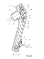
- Bei diesem Ausführungsbeispiel ist es wiederum möglich, dass, falls die Achsen 32 des Schließzylinders und des Schließmechanismus in einem spitzen Winkel liegen, trotzdem die Öffnungs- und Schließbewegung möglich ist. Bei dem Ausführungsbeispiel nach Fig. 11 ist wiederum eine Abbiegung 43 an der Übertragungsstange vorgesehen, hierbei trägt die Abbiegung eine Ausnehmung 44, in der der drehknaufartige Teil 39 der Kurbelachse eingreift.
- Auch hier schneiden sich die beiden Achsen von Schlossvorrichtung und Schließzylinder. Durch die schlitzartige Ausnehmung 44 wird erreicht, dass bei Drehung des Schließzylinders um einen ersten Betrag das untere Drehteil in der jetzigen dargestellten Stellung verbleibt. Erst wenn der Knauf 39 am oberen Ende der schlitzartigen Ausnehmung 34 sich befindet, wird die Drehbewegung und damit das Öffnen oder Schließen des Schlosses eingeleitet. Wichtig ist, dass dadurch der erste Teil der Drehbewegung des oberen Drehteiles ohne Drehung des unteren Teiles verläuft, sich die Stange je nachdem, wie sie gedreht wird, entweder nach links oder nach rechts verschwenkt, so dass dann bei einer weiteren Bewegung die Schlossvorrichtung in Ihre Schließ- oder Offenstellung überführt werden kann, wie die Ausführungsform gemäß Fig. 2, Fig. 3 und Fig. 4 zeigt.
- Wie zu erkennen ist, ist das Drehteil 24 mit einer Rückstellfeder 37 versehen, die es ermöglicht, dass nach jedem Öffnungsvorgang und Freigabe des Schlüssels die Ausgangsstellung eingestellt wird.
- Bei dem Ausführungsbeispiel nach den Fig. 12 bis 15 ist schematisch eine Schließvorrichtung dargestellt, bei der wiederum die Achse des Schließzylinders sowie die Achse der Schlossvorrichtung in einem Winkel zueinander angeordnet sind.
- Am oberen Drehteil 24 ist klippsartig die Übertragungsstange 30 befestigt. Am unteren Drehteil 27 ist mittig eine knaufartige Befestigungsstelle 50 vorgesehen. An diese knaufartige Befestigungsstelle wird ein Schwenkhebel 45 aufgeklippst. Dieser Schwenkhebel ist sowohl drehbar als auch von dem Drehteil weg schwenkbar gelagert.
- Bei Einleitung der Drehung, vergl. Fig. 13, wird die Übertragungsstange verschwenkt, hierdurch bedingt müsste entweder der Schwenkhebel 45 eine Drehbewegung ausführen oder aber, er schwenkt vom unteren Drehteil weg, wie dieses Fig. 14 zeigt. Bei einer weiteren Drehung der oberen Drehscheibe 48 schlägt der Schwenkansatz schließlich gegen Anschläge 46 bzw. 47 und vergl. Fig. 15, und kann dann das untere Drehteil mit bewegen. Durch den Schwenkhebel wird sichergestellt, dass bei Einleitung der Drehbewegung ausgehend von Fig. 12 eine genaue Mitnahme des unteren Drehteiles erfolgt.
- Durch eine nicht dargestellte Feder ist wiederum bei Freigabe der Schließvorrichtung selbsttätig die Ausgangsstelle einstellbar. Bei einer Bewegung dann im Uhrzeigerrichtung würde sich das untere Drehteil auch in Uhrzeigerrichtung drehen, hierbei würde aber zunächst die Schwenkbewegung des Schwenkeinsatzes eintreten, bis der Schwenkhebel schließlich gegen den Anschlag 47 stoßen würde.
- Wie bereits erwähnt, sind die dargestellten Ausführungsformen beispielsweise Verwirklichungen der Erfindung. Diese ist nicht darauf beschränkt. Vielmehr sind noch mancherlei Abänderungen und Anwendungen möglich. Insbesondere könnten die Rückstellfeder sowohl am oberen als auch am unteren Drehteil vorgesehen sein. Das Übertragungsteil kann aus einem Blechstreifen oder aus einem Kunststoffspritzteil bestehen. Die Erfindung besteht auch darin, dass bei einer Stangenlösung der Fall ± 90° Grad-Drehwinkel des Zylinderschlosses eingesetzt werden kann.
-
- 19
- Schließvorrichtung
- 20
- Schließzylinder
- 21
- Schlüssel
- 22
- Schlossmechanismus
- 23
- Übertragungspaddel
- 24
- Drehteil oben
- 25
- Drehachse
- 26
- Kurbelzapfen
- 27
- Drehteil unten
- 28
- Drehachse
- 29
- Kurbelzapfen
- 30
- Übertragungsstange
- 31
- Gehäusewand
- 32
- Schließzylinderachse
- 33
- Schlossachse
- 34
- schlitzartige Ausnehmung
- 35
- Gehäuse
- 36
- Kurbelarm
- 37
- Rückstellfeder 37
- 39
- Drehknauf
- 40
- Lagerschale
- 41
- U-förmiger Drehabschnitt von 27
- 42
- seitlicher Arm an 41
- 43
- Abbiegung an 30
- 44
- Ausnehmung
- 45
- Schwenkhebel
- 46
- Anschlag
- 47
- Anschlag
- 48
- Drehscheibe oben
- 49
- Drehscheibe unten
- 50
- Befestigungsstelle
Claims (11)
- Schließvorrichtung, insbesondere für Kraftfahrzeugtüren, mit einem durch einen Schlüssel (21) zu betätigenden Schließzylinder (20), mit einem Schlossmechanismus (22) zur Ver- oder Entriegelung der Tür und mit einem Übertragungsteil (30) zwischen Schließzylinder (20) und Schlossmechanismus (22), hierbei ist drehfest mit dem Schließzylinder (20) und mit dem Schlossmechanismus (22) jeweils ein Drehteil (24,27) verbunden, an dem das Übertragungsteil angreift,
dadurch gekennzeichnet,
dass das Übertragungsteil (30) stangenartig ausgebildet ist, dass sowohl das dem Schließzylinder (20) zugeordnete Drehteil (24) als auch das dem Schlossmechanismus (22) zugeordnete Drehteil (27) kurbelartig mit einer Drehachse ( 25,28) ausgebildet ist, und mit wenigstens einem Kurbelzapfen (26,29), dass an dem Kurbelzapfen (26,29) das stangenartige Übertragungsteil (30) angeordnet ist, hierbei führt bei einer Drehbewegung des Drehteiles (25,27) des Schließzylinders (20) das Übertragungsteil (30) sowohl eine Schwenkbewegung als auch eine Translationsbewegung aus, bei der das Drehteil (27) des Schlossmechanismus (22) mitbewegbar ist. - Schließvorrichtung nach Anspruch 1, dadurch gekennzeichnet, dass wenigstens eines der Drehteile (24,27) von Schließzylinder (20) und/oder Schlossmechanismus (22) mit einer Feder (37) belastet ist, die das Drehteil (24,27) bei Freigabe in eine Ausgangslage zurückdreht.
- Schließvorrichtung nach Anspruch 1 oder 2, dadurch gekennzeichnet, dass das Übertragungsteil (30) einen schlitzartigen Durchbruch (34) aufweist, in der der Kurbelzapfen (26,29) des Drehteiles (24,27) eingreift.
- Schließvorrichtung nach einem der Ansprüche 1 bis 3, dadurch gekennzeichnet, dass das Drehteil (24,27) eine Doppellagerung aufweist, hierbei ist zwischen den beiden Lagerstellen das Übertragungsteil (30) angeordnet.
- Schließvorrichtung nach einem der Ansprüche 1 bis 4, dadurch gekennzeichnet, dass das Drehteil (24,27) zwei stangenartige Übertragungsteile (30) aufweist, hierbei trägt ein Kurbelzapfen (26,29) das eine Übertragungsteil (30) und ein zweiter genau entgegengesetzt gerichteter Kurbelzapfen (26,29) das zweite Übertragungsteil (30), wobei in Achsrichtung (25,28) gesehen die beiden Kurbelzapfen (26,29) an dem Drehteil (24,27) um einen Winkelbetrag von wenigstens 30° Grad auseinanderliegen.
- Schließvorrichtung nach einem der Ansprüche 1 bis 5, dadurch gekennzeichnet, dass die beiden Kurbelzapfen (26,29) an einem ankerartigen Zwischenstück (41,42) angeordnet sind.
- Schließvorrichtung nach einem der Ansprüche 1 bis 6, dadurch gekennzeichnet, dass das stangenartige Übertragungsteil (30) in seiner Längsrichtung eine Abbiegung (30) umfasst.
- Schließvorrichtung nach einem der Ansprüche 1 bis 7, dadurch gekennzeichnet, dass die Abbiegung im Bereich der Langlochausnehmung (44) des Übertragungsteiles (30) liegt.
- Schließvorrichtung nach einem der Ansprüche 1 bis 8, dadurch gekennzeichnet, dass das Übertragungsteil (30) durch eine Rastverbindung an dem Drehteil (24,27) festlegbar ist.
- Schließvorrichtung nach Anspruch 9, dadurch gekennzeichnet, dass zur Lagerung des Überragungsteils (30) am Drehteil (24,27) ein kugelförmiger Abschnitt (39) vorgesehen ist, auf dem die Übertragungsstange (30) mit einer entsprechenden Lagerschale (40) aufklippsbar ist.
- Schließvorrichtung nach einem der Ansprüche 1 bis 10, dass an dem Drehteil (24,27) des Schlossmechanismus (22) ein Schwenkdrehhebel (45) angeordnet ist, der die zweite Lagerstelle für das Übertragungsteil (30) bildet, hierbei ist der Schwenkhebel (45) sowohl drehbar als auch kippbar angeordnet, wobei zur Begrenzung der Drehbewegung Anschläge (46,27) am Drehteil (27) vorgesehen sind.
Applications Claiming Priority (2)
| Application Number | Priority Date | Filing Date | Title |
|---|---|---|---|
| DE10135265 | 2001-07-19 | ||
| DE10135265A DE10135265A1 (de) | 2001-07-19 | 2001-07-19 | Schließvorrichtung |
Publications (2)
| Publication Number | Publication Date |
|---|---|
| EP1279783A1 true EP1279783A1 (de) | 2003-01-29 |
| EP1279783B1 EP1279783B1 (de) | 2004-06-30 |
Family
ID=7692410
Family Applications (1)
| Application Number | Title | Priority Date | Filing Date |
|---|---|---|---|
| EP02014763A Expired - Lifetime EP1279783B1 (de) | 2001-07-19 | 2002-07-04 | Schliessvorrichtung |
Country Status (3)
| Country | Link |
|---|---|
| EP (1) | EP1279783B1 (de) |
| DE (2) | DE10135265A1 (de) |
| ES (1) | ES2219605T3 (de) |
Cited By (8)
| Publication number | Priority date | Publication date | Assignee | Title |
|---|---|---|---|---|
| FR2923249A1 (fr) * | 2007-11-07 | 2009-05-08 | Valeo Securite Habitacle Sas | Agencement de montage d'un joint de cardan de connexion du barillet d'un verrou sur une serrure |
| FR2985534A1 (fr) * | 2012-01-05 | 2013-07-12 | Peugeot Citroen Automobiles Sa | Dispositif d'interface entre un verrou et une serrure d'une porte de vehicule, a pignons et moyens de couplage |
| WO2013139591A1 (fr) * | 2012-03-22 | 2013-09-26 | Peugeot Citroen Automobiles Sa | Dispositif d'interface entre un verrou et une serrure d'une porte de véhicule, à roues, câble(s) et arbre de contournement |
| WO2013083115A3 (de) * | 2011-12-09 | 2013-09-26 | Kiekert Aktiengesellschaft | Aussenverriegelungsmodul für ein schloss |
| EP2333205A4 (de) * | 2008-09-16 | 2014-11-05 | Honda Lock Kk | Öfnungs-/schliessvorrichtung für eine fahrzeugtür |
| DE102014112735A1 (de) * | 2014-09-04 | 2016-03-10 | Kiekert Ag | Kraftfahrzeugtürschloss |
| US10337215B2 (en) * | 2014-10-07 | 2019-07-02 | Kiekert Ag | Motor vehicle door lock |
| EP3702560A1 (de) * | 2019-02-20 | 2020-09-02 | Toyota Jidosha Kabushiki Kaisha | Mechanismus zum betätigen eines autoschlüssels |
Families Citing this family (2)
| Publication number | Priority date | Publication date | Assignee | Title |
|---|---|---|---|---|
| FR2895762A1 (fr) * | 2005-12-30 | 2007-07-06 | Valeo Securite Habitacle Sas | Verrou debrayable pour un mecanisme de serrure automobile |
| JP6690100B2 (ja) * | 2015-12-24 | 2020-04-28 | 三井金属アクト株式会社 | 車両ドア用ラッチ集合体 |
Citations (5)
| Publication number | Priority date | Publication date | Assignee | Title |
|---|---|---|---|---|
| EP0722028A1 (de) * | 1995-01-14 | 1996-07-17 | Rockwell Light Vehicle Systems (Uk) Limited | Kraftwagentürschloss |
| US5666834A (en) * | 1993-12-24 | 1997-09-16 | Mitsui Kinzoku Kogyo Kabushiki Kaisha | Anti-theft mechanism for a vehicle door lock device |
| DE19745620A1 (de) * | 1997-10-16 | 1999-04-22 | Krosta Gmbh & Co Kg Nachfolger | Haubenverschluß |
| DE19961247A1 (de) * | 1999-02-17 | 2000-08-24 | Huf Huelsbeck & Fuerst Gmbh | Türschloss, insbesondere für Kraftfahrzeuge |
| DE19961885A1 (de) * | 1999-12-20 | 2001-06-28 | Huf Huelsbeck & Fuerst Gmbh | Vorrichtung zur Fernentriegelung von Schlössern, insbesondere bei Kfz |
Family Cites Families (5)
| Publication number | Priority date | Publication date | Assignee | Title |
|---|---|---|---|---|
| US4155233A (en) * | 1977-09-28 | 1979-05-22 | Christopher Ward | Deck lid lock safety release |
| US4426858A (en) * | 1981-06-01 | 1984-01-24 | Bruno Interrante | Tamper deactivating assembly |
| DE4219209C2 (de) * | 1992-06-12 | 2002-03-14 | Valeo Auto Electric Gmbh | Verriegelungsvorrichtung |
| US5493881A (en) * | 1993-09-17 | 1996-02-27 | Harvey; Steven M. | Electric door lock for vehicle storage compartments |
| DE19756266A1 (de) * | 1997-12-18 | 1999-06-24 | Mannesmann Vdo Ag | Schließeinrichtung |
-
2001
- 2001-07-19 DE DE10135265A patent/DE10135265A1/de not_active Withdrawn
-
2002
- 2002-07-04 DE DE50200564T patent/DE50200564D1/de not_active Expired - Lifetime
- 2002-07-04 ES ES02014763T patent/ES2219605T3/es not_active Expired - Lifetime
- 2002-07-04 EP EP02014763A patent/EP1279783B1/de not_active Expired - Lifetime
Patent Citations (5)
| Publication number | Priority date | Publication date | Assignee | Title |
|---|---|---|---|---|
| US5666834A (en) * | 1993-12-24 | 1997-09-16 | Mitsui Kinzoku Kogyo Kabushiki Kaisha | Anti-theft mechanism for a vehicle door lock device |
| EP0722028A1 (de) * | 1995-01-14 | 1996-07-17 | Rockwell Light Vehicle Systems (Uk) Limited | Kraftwagentürschloss |
| DE19745620A1 (de) * | 1997-10-16 | 1999-04-22 | Krosta Gmbh & Co Kg Nachfolger | Haubenverschluß |
| DE19961247A1 (de) * | 1999-02-17 | 2000-08-24 | Huf Huelsbeck & Fuerst Gmbh | Türschloss, insbesondere für Kraftfahrzeuge |
| DE19961885A1 (de) * | 1999-12-20 | 2001-06-28 | Huf Huelsbeck & Fuerst Gmbh | Vorrichtung zur Fernentriegelung von Schlössern, insbesondere bei Kfz |
Cited By (14)
| Publication number | Priority date | Publication date | Assignee | Title |
|---|---|---|---|---|
| WO2009059904A1 (fr) * | 2007-11-07 | 2009-05-14 | Valeo Securite Habitacle | Agencement de montage d'un joint de cardan de connexion du barillet d'un verrou sur une serrure |
| FR2923249A1 (fr) * | 2007-11-07 | 2009-05-08 | Valeo Securite Habitacle Sas | Agencement de montage d'un joint de cardan de connexion du barillet d'un verrou sur une serrure |
| EP2333205A4 (de) * | 2008-09-16 | 2014-11-05 | Honda Lock Kk | Öfnungs-/schliessvorrichtung für eine fahrzeugtür |
| US9482037B2 (en) | 2011-12-09 | 2016-11-01 | Kiekert Aktiengesellschaft | Exterior locking module for a lock |
| WO2013083115A3 (de) * | 2011-12-09 | 2013-09-26 | Kiekert Aktiengesellschaft | Aussenverriegelungsmodul für ein schloss |
| CN103975114B (zh) * | 2011-12-09 | 2017-04-26 | 开开特股份公司 | 用于锁的外部闭锁模块 |
| CN103975114A (zh) * | 2011-12-09 | 2014-08-06 | 开开特股份公司 | 用于锁的外部闭锁模块 |
| KR20140106570A (ko) * | 2011-12-09 | 2014-09-03 | 키커트 악티엔게젤샤프트 | 록용 외부 록킹 모듈 |
| FR2985534A1 (fr) * | 2012-01-05 | 2013-07-12 | Peugeot Citroen Automobiles Sa | Dispositif d'interface entre un verrou et une serrure d'une porte de vehicule, a pignons et moyens de couplage |
| WO2013139591A1 (fr) * | 2012-03-22 | 2013-09-26 | Peugeot Citroen Automobiles Sa | Dispositif d'interface entre un verrou et une serrure d'une porte de véhicule, à roues, câble(s) et arbre de contournement |
| FR2988418A1 (fr) * | 2012-03-22 | 2013-09-27 | Peugeot Citroen Automobiles Sa | Dispositif d'interface entre un verrou et une serrure d'une porte de vehicule, a roues, cable(s) et arbre de contournement |
| DE102014112735A1 (de) * | 2014-09-04 | 2016-03-10 | Kiekert Ag | Kraftfahrzeugtürschloss |
| US10337215B2 (en) * | 2014-10-07 | 2019-07-02 | Kiekert Ag | Motor vehicle door lock |
| EP3702560A1 (de) * | 2019-02-20 | 2020-09-02 | Toyota Jidosha Kabushiki Kaisha | Mechanismus zum betätigen eines autoschlüssels |
Also Published As
| Publication number | Publication date |
|---|---|
| EP1279783B1 (de) | 2004-06-30 |
| ES2219605T3 (es) | 2004-12-01 |
| DE10135265A1 (de) | 2003-02-06 |
| DE50200564D1 (de) | 2004-08-05 |
Similar Documents
| Publication | Publication Date | Title |
|---|---|---|
| DE3343161C2 (de) | ||
| DE69808823T2 (de) | Schliessfolgeregler für eine zweiflügelige Tür | |
| EP1279783B1 (de) | Schliessvorrichtung | |
| DE2916559C2 (de) | Lenkschloß | |
| DE10126909A1 (de) | Schließvorrichtung | |
| DE9007232U1 (de) | Treibstangenverschluß | |
| WO1994010415A1 (de) | Drehriegelverschluss | |
| DE19916191A1 (de) | Vorrichtung zur Verriegelung einer Haube eines Kraftfahrzeuges | |
| DE4421036C1 (de) | Schloß zur Verwendung als Links- oder Rechtsschloß | |
| DE3636236A1 (de) | Panikverschluss fuer zweifluegelige tueren | |
| DE10143028A1 (de) | Seitentür eines Kraftfahrzeugs | |
| DE69807608T2 (de) | Schliessvorrichtung, insbesondere Einsteckschloss mit einer Falle, für eine Fenstertür oder dergleichen | |
| EP1959076B1 (de) | Schließautomat für einen Tür-oder Fensterflügel | |
| EP3396086A1 (de) | Türöffner mit sperrhebel zwischen falle und wechsel | |
| DE602005000231T2 (de) | Lenkschloss für Fahrzeuglenkvorrichtung | |
| EP2787137B1 (de) | Verriegelungsvorrichtung | |
| DE69807801T2 (de) | Verriegelungsvorrichtung, insbesondere Einsteckschloss für den Flügel einer Tür oder eines Fensters | |
| DE10151870A1 (de) | Vorrichtung zur Betätigung eines Verschlusses von Türen oder Klappen, insbesondere an Fahrzeugen | |
| DE3901936C2 (de) | Drehstangenverschluß | |
| DE69204044T2 (de) | Sicherheitsschloss für eine Haustüre oder dgl. | |
| EP0391063B1 (de) | Treibstangenschloss | |
| AT224494B (de) | Betätigungseinrichtung für Dreh-Kipp-Fenster, -Türen od. ähnl. Öffnungsverschlüsse | |
| DE9210719U1 (de) | Türschloß | |
| DE10246969B4 (de) | Vorrichtung mit einem Griff für Fenster, Türen od. dgl. | |
| EP1268243A1 (de) | Lenkschloss für fahrzeuge, insbesondere kraftfahrzeuge |
Legal Events
| Date | Code | Title | Description |
|---|---|---|---|
| PUAI | Public reference made under article 153(3) epc to a published international application that has entered the european phase |
Free format text: ORIGINAL CODE: 0009012 |
|
| AK | Designated contracting states |
Designated state(s): AT BE BG CH CY CZ DE DK EE ES FI FR GB GR IE IT LI LU MC NL PT SE SK TR |
|
| AX | Request for extension of the european patent |
Extension state: AL LT LV MK RO SI |
|
| 17P | Request for examination filed |
Effective date: 20030513 |
|
| AKX | Designation fees paid |
Designated state(s): DE ES FR GB IT |
|
| GRAP | Despatch of communication of intention to grant a patent |
Free format text: ORIGINAL CODE: EPIDOSNIGR1 |
|
| GRAS | Grant fee paid |
Free format text: ORIGINAL CODE: EPIDOSNIGR3 |
|
| GRAA | (expected) grant |
Free format text: ORIGINAL CODE: 0009210 |
|
| AK | Designated contracting states |
Kind code of ref document: B1 Designated state(s): DE ES FR GB IT |
|
| REG | Reference to a national code |
Ref country code: GB Ref legal event code: FG4D Free format text: NOT ENGLISH |
|
| REG | Reference to a national code |
Ref country code: IE Ref legal event code: FG4D Free format text: GERMAN |
|
| REF | Corresponds to: |
Ref document number: 50200564 Country of ref document: DE Date of ref document: 20040805 Kind code of ref document: P |
|
| GBT | Gb: translation of ep patent filed (gb section 77(6)(a)/1977) |
Effective date: 20041019 |
|
| REG | Reference to a national code |
Ref country code: ES Ref legal event code: FG2A Ref document number: 2219605 Country of ref document: ES Kind code of ref document: T3 |
|
| ET | Fr: translation filed | ||
| REG | Reference to a national code |
Ref country code: IE Ref legal event code: FD4D |
|
| PLBE | No opposition filed within time limit |
Free format text: ORIGINAL CODE: 0009261 |
|
| STAA | Information on the status of an ep patent application or granted ep patent |
Free format text: STATUS: NO OPPOSITION FILED WITHIN TIME LIMIT |
|
| 26N | No opposition filed |
Effective date: 20050331 |
|
| PGFP | Annual fee paid to national office [announced via postgrant information from national office to epo] |
Ref country code: ES Payment date: 20070720 Year of fee payment: 6 |
|
| PGFP | Annual fee paid to national office [announced via postgrant information from national office to epo] |
Ref country code: GB Payment date: 20070723 Year of fee payment: 6 |
|
| PGFP | Annual fee paid to national office [announced via postgrant information from national office to epo] |
Ref country code: IT Payment date: 20070726 Year of fee payment: 6 |
|
| PGFP | Annual fee paid to national office [announced via postgrant information from national office to epo] |
Ref country code: FR Payment date: 20070718 Year of fee payment: 6 |
|
| GBPC | Gb: european patent ceased through non-payment of renewal fee |
Effective date: 20080704 |
|
| REG | Reference to a national code |
Ref country code: FR Ref legal event code: ST Effective date: 20090331 |
|
| PG25 | Lapsed in a contracting state [announced via postgrant information from national office to epo] |
Ref country code: GB Free format text: LAPSE BECAUSE OF NON-PAYMENT OF DUE FEES Effective date: 20080704 |
|
| PG25 | Lapsed in a contracting state [announced via postgrant information from national office to epo] |
Ref country code: FR Free format text: LAPSE BECAUSE OF NON-PAYMENT OF DUE FEES Effective date: 20080731 Ref country code: IT Free format text: LAPSE BECAUSE OF NON-PAYMENT OF DUE FEES Effective date: 20080704 |
|
| REG | Reference to a national code |
Ref country code: ES Ref legal event code: FD2A Effective date: 20080705 |
|
| PG25 | Lapsed in a contracting state [announced via postgrant information from national office to epo] |
Ref country code: ES Free format text: LAPSE BECAUSE OF NON-PAYMENT OF DUE FEES Effective date: 20080705 |
|
| REG | Reference to a national code |
Ref country code: DE Ref legal event code: R084 Ref document number: 50200564 Country of ref document: DE |
|
| REG | Reference to a national code |
Ref country code: DE Ref legal event code: R084 Ref document number: 50200564 Country of ref document: DE Effective date: 20110701 |
|
| PGFP | Annual fee paid to national office [announced via postgrant information from national office to epo] |
Ref country code: DE Payment date: 20180621 Year of fee payment: 17 |
|
| REG | Reference to a national code |
Ref country code: DE Ref legal event code: R119 Ref document number: 50200564 Country of ref document: DE |
|
| PG25 | Lapsed in a contracting state [announced via postgrant information from national office to epo] |
Ref country code: DE Free format text: LAPSE BECAUSE OF NON-PAYMENT OF DUE FEES Effective date: 20200201 |