EP1277935A2 - Zusammenbau von Brennstoffbehälter- und pumpe für einen Aussenbordmotor - Google Patents
Zusammenbau von Brennstoffbehälter- und pumpe für einen Aussenbordmotor Download PDFInfo
- Publication number
- EP1277935A2 EP1277935A2 EP02015655A EP02015655A EP1277935A2 EP 1277935 A2 EP1277935 A2 EP 1277935A2 EP 02015655 A EP02015655 A EP 02015655A EP 02015655 A EP02015655 A EP 02015655A EP 1277935 A2 EP1277935 A2 EP 1277935A2
- Authority
- EP
- European Patent Office
- Prior art keywords
- fuel tank
- auxiliary fuel
- auxiliary
- fuel
- fuel pump
- Prior art date
- Legal status (The legal status is an assumption and is not a legal conclusion. Google has not performed a legal analysis and makes no representation as to the accuracy of the status listed.)
- Granted
Links
Images


Classifications
-
- F—MECHANICAL ENGINEERING; LIGHTING; HEATING; WEAPONS; BLASTING
- F02—COMBUSTION ENGINES; HOT-GAS OR COMBUSTION-PRODUCT ENGINE PLANTS
- F02B—INTERNAL-COMBUSTION PISTON ENGINES; COMBUSTION ENGINES IN GENERAL
- F02B61/00—Adaptations of engines for driving vehicles or for driving propellers; Combinations of engines with gearing
- F02B61/04—Adaptations of engines for driving vehicles or for driving propellers; Combinations of engines with gearing for driving propellers
- F02B61/045—Adaptations of engines for driving vehicles or for driving propellers; Combinations of engines with gearing for driving propellers for marine engines
-
- B—PERFORMING OPERATIONS; TRANSPORTING
- B63—SHIPS OR OTHER WATERBORNE VESSELS; RELATED EQUIPMENT
- B63B—SHIPS OR OTHER WATERBORNE VESSELS; EQUIPMENT FOR SHIPPING
- B63B17/00—Vessels parts, details, or accessories, not otherwise provided for
- B63B17/0027—Tanks for fuel or the like ; Accessories therefor, e.g. tank filler caps
-
- B—PERFORMING OPERATIONS; TRANSPORTING
- B63—SHIPS OR OTHER WATERBORNE VESSELS; RELATED EQUIPMENT
- B63H—MARINE PROPULSION OR STEERING
- B63H20/00—Outboard propulsion units, e.g. outboard motors or Z-drives; Arrangements thereof on vessels
- B63H20/001—Arrangements, apparatus and methods for handling fluids used in outboard drives
-
- F—MECHANICAL ENGINEERING; LIGHTING; HEATING; WEAPONS; BLASTING
- F02—COMBUSTION ENGINES; HOT-GAS OR COMBUSTION-PRODUCT ENGINE PLANTS
- F02B—INTERNAL-COMBUSTION PISTON ENGINES; COMBUSTION ENGINES IN GENERAL
- F02B75/00—Other engines
- F02B75/16—Engines characterised by number of cylinders, e.g. single-cylinder engines
- F02B75/18—Multi-cylinder engines
- F02B75/22—Multi-cylinder engines with cylinders in V, fan, or star arrangement
-
- F—MECHANICAL ENGINEERING; LIGHTING; HEATING; WEAPONS; BLASTING
- F02—COMBUSTION ENGINES; HOT-GAS OR COMBUSTION-PRODUCT ENGINE PLANTS
- F02B—INTERNAL-COMBUSTION PISTON ENGINES; COMBUSTION ENGINES IN GENERAL
- F02B75/00—Other engines
- F02B75/16—Engines characterised by number of cylinders, e.g. single-cylinder engines
- F02B75/18—Multi-cylinder engines
- F02B2075/1804—Number of cylinders
- F02B2075/1824—Number of cylinders six
Definitions
- the present invention relates to an improvement in an outboard motor auxiliary fuel tank/fuel pump assembly that includes an auxiliary fuel tank that is disposed in a space on either of the front, back, left and right sides of an engine in an engine compartment of an outboard motor and stores fuel that is fed from a fuel tank.
- a conventional outboard motor auxiliary fuel tank/fuel pump assembly is already known and disclosed in, for example, Japanese Patent Application Laid-open No. 10-184375.
- a space located either to the front or rear of the engine or the left or right side of the engine is utilized to position the assembly depending on the type of engine. It is well known in the industry that even in a state where the outboard motor is tilted up, for example, when traveling in shallow water, it is necessary for the pivot shaft of the float valve of the auxiliary fuel tank to always be parallel relative to the tilt shaft of the outboard motor in order to secure normal operation of the float valve. Therefore, when the auxiliary fuel tank/fuel pump assembly is installed in any of the above-mentioned front, rear, left, and right spaces, the orientation of the auxiliary fuel tank is determined by the orientation of the pivot shaft of the float valve.
- auxiliary fuel tank and the fuel pump to be connected so as to be aligned in the left-and-right direction when the auxiliary fuel tank/fuel pump assembly is arranged in the space to the front or rear of the engine. Furthermore, it is necessary for the auxiliary fuel tank and the fuel pump to be connected so as to be aligned in the front-and-rear direction when the assembly is arranged in the space on the left or right side of the engine. Because of this difference in the position of the auxiliary fuel tank to which the fuel pump is connected, a different conventional auxiliary fuel tank is used exclusively for each of the above-described cases and is produced so as to correspond to the space where the auxiliary fuel tank/fuel pump assembly is installed. This decreases the effectiveness of mass-producing the auxiliary fuel tank, which results in increasing manufacturing costs.
- the structural arrangement of the present invention increases the effectiveness of mass-producing the auxiliary fuel tank, improves space efficiency, and decreases manufacturing costs.
- an outboard motor auxiliary fuel tank/fuel pump assembly that includes an auxiliary fuel tank disposed in an engine compartment of an outboard motor that stores fuel fed from a fuel tank on a hull side.
- a fuel pump is joined to one side of the auxiliary fuel tank and supplies the fuel stored within the auxiliary fuel tank to a fuel injection valve of an engine.
- a float valve having a float is provided within the auxiliary fuel tank and opens/closes a fuel inlet port of the auxiliary fuel tank according to the level of the stored fuel.
- the float is supported in a vertically swingable manner in the auxiliary fuel tank via a pivot shaft that is parallel to a tilt shaft of the outboard motor.
- the assembly also includes first and second mounting parts on which the fuel pump is mounted.
- the first and second mounting parts are formed, respectively, on an outer face of the auxiliary fuel tank that is vertical and perpendicular to the tilt shaft and on an outer face of the auxiliary fuel tank that is vertical and parallel to the tilt shaft.
- the same type of auxiliary fuel tank can be used where the auxiliary fuel tank/fuel pump assembly is arranged in the space to the front or rear of the engine by connecting the auxiliary fuel tank and the fuel pump so as to be aligned in the left-and-right direction, and where the auxiliary fuel tank/fuel pump assembly is arranged in the space on the left or right side of the engine by connecting the auxiliary fuel tank and the fuel pump so as to be aligned in the front-and-rear direction. It is therefore possible to reasonably provide a structural arrangement of the auxiliary fuel tank/fuel pump assembly using the same type of auxiliary fuel tank in all cases, thereby enhancing the space efficiency and mass-production of the auxiliary fuel tank. Moreover, in all cases, since the pivot shaft of the float valve within the auxiliary fuel tank is maintained parallel to the tilt shaft, the float valve can properly be operated when the outboard motor is tilted up.
- an outboard motor auxiliary fuel tank/fuel pump assembly that further includes first and second connecting bosses provided, respectively, on the outer face of the auxiliary fuel tank on which the first mounting part has been formed and on the outer face of the auxiliary fuel tank on which the second mounting part has been formed.
- a suction pipe of the fuel pump is connected to the first and second connecting bosses.
- the connecting bosses include a blocking wall through which a hole is made when the suction pipe is connected thereto.
- the suction pipe is connected to the corresponding connecting boss at the same time, such that the connection operation is performed rather rapidly.
- the first and second mounting parts may correspond to first and second bosses, and the fuel pump may correspond to a secondary fuel pump.
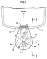
- FIG. 1 is a schematic diagram of a plan view of an outboard motor illustrating an auxiliary fuel tank/fuel pump assembly according to the preferred embodiment of the present invention
- FIG. 2 is a cross-sectional side view taken along line 2-2 of Fig. 1;
- FIG. 3 is a cross-sectional view taken along line 3-3 of Fig. 2;
- FIG. 4 is a schematic diagram of an engine fuel supply system in the outboard motor
- FIG. 5 is an enlarged view of the auxiliary fuel tank/fuel pump assembly of Fig. 3;
- FIG. 6 is a view from arrow 6 of Fig. 5;
- FIG. 7 is a view from arrow 7 of Fig. 5;
- FIG. 8 is a partial cross-sectional view taken along line 8-8 of Fig. 6;
- FIG. 9 is a partial cross-sectional view taken along line 9-9 of Fig. 5;
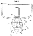
- FIG. 10 is a schematic diagram of a plan view of an outboard motor illustrating the auxiliary fuel tank/fuel pump assembly according to a second embodiment of the present invention.
- FIG. 11 is an enlarged view of the auxiliary fuel tank/fuel pump assembly of Fig. 10;
- FIG. 12 is a side view of Fig. 11.
- FIG. 13 is a partial cross-sectional view taken along line 13-13 of Fig. 12.
- a propulsion unit U of the outboard motor O 1 in which the auxiliary fuel tank/fuel pump assembly A is provided includes a mount case 1, an extension case 2 attached to the lower end face of the mount case 1, and a gear case 3 attached to the lower end face of the extension case 2.
- a V6 water-cooled four-stroke engine E 1 is mounted on the upper end face of the mount case 1 so that its crankshaft 4 is vertical.
- An annular undercover 14 is fixed to the mount case 1.
- the undercover 14 covers a section extending from a lower part of the engine E 1 to an upper part of the extension case 2.
- Detachably fixed to the upper end of the undercover 14 is an engine hood 15 that covers the top of the engine E 1 .
- the engine hood 15 and undercover 14 define an engine compartment 16 housing the engine E 1 .
- a drive shaft 50 connected to the crankshaft 4 of the engine E 1 extends downward within the extension case 2.
- the drive shaft 50 is connected at a lower end, via a forward/reverse mechanism 51 provided within the gear case 3, to a propeller shaft 52 having a propeller 53 at the rear end thereof, thereby forming the propulsion unit U.
- a swivel shaft 55 is fixed between a pair of left and right upper arms 54a connected to the mount case 1 and a pair of left and right lower arms 54b connected to the extension case 2.
- a swivel case 56 rotatably supporting the swivel shaft 55 is supported in a vertically swingable manner, via a tilt shaft 58 that is horizontal in the left-and-right direction, by a stem bracket 57 attached to a transom Ht of the hull H. It is therefore possible to prevent the propeller 53 from grounding when traveling in shallow water by tilting the propulsion unit U upward around the tilt shaft 58 through an appropriate angle.
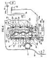
- the engine E 1 includes a crankcase 5 supporting the crankshaft 4 and a pair of left and right banks 6L and 6R extending from the crankcase 5 in a V-shape toward the rear.
- the lower face of the crankcase 5 is joined by a bolt to the upper face of the mount case 1.
- Each of the banks 6L and 6R includes a plurality of cylinder bores 7L or 7R that are aligned vertically. It should be noted that while Fig. 3 illustrates three cylinder bores, the number shown is merely exemplary, and it is within the scope of the invention to include as many cylinder bores in each bank as required by the particular engine design.
- FIGs. 3 and 4 attached to intake pipes 11L and 11R of the left and right banks 6L and 6R are electromagnetic fuel injection valves 12L and 12R that inject fuel toward the downstream side of the intake pipes.
- Left and right fuel rails 20L and 20R are provided for distributing fuel between the fuel injection valves 12L and12R.
- a primary fuel pump 21 Installed on a head part of one of the banks 6L and 6R is a primary fuel pump 21, for example only, a diaphragm-type pump, mechanically driven by a valve-operating cam shaft installed within the head part.
- a first fuel pipe 24a connected to a suction port 23 of the primary fuel pump 21 is connected, via a joint 25, to a fuel bearing pipe 27 extending from a fuel tank 26 installed on the hull H side.
- first fuel filter 29 Disposed partway'along the first fuel pipe 24a are a first fuel filter 29 and a second fuel filter 30, in that order, from the upstream side.
- the first fuel filter 29 removes moisture from the fuel
- the second fuel filter 30 removes other foreign substances from the fuel.
- An auxiliary fuel tank 35 is disposed on top of the mount case 1 in a space to the rear of the engine E 1 within the engine compartment 16.
- a fuel inlet port 36 to which a discharge port 31 of the primary fuel pump 21 is connected via a second fuel pipe 24b.
- a known float valve 37 which closes the fuel inlet port 36 when the level of the stored fuel becomes equal to or greater than a predetermined level.
- a motor-operated secondary fuel pump 40 for pumping out the fuel stored therein.
- the auxiliary fuel tank 35 and secondary fuel pump 40 together, form the auxiliary fuel tank/fuel pump assembly A.
- a discharge port 41 of the secondary fuel pump 40 is connected to the upper end of the right fuel rail 20R via a third fuel pipe 24c.
- High pressure fuel discharged from the secondary fuel pump 40 fills the right fuel rail 20R from its upper end and then the left fuel rail 20L from its lower end via a communicating pipe 60, and is supplied to each of the fuel injection valves 12L and 12R.
- a fuel pressure adjuster 61 for adjusting the pressures within the two fuel rails 20L and 20R, that is, the fuel injection pressure of each of the fuel injection valves 12L and 12R.
- a fuel return pipe, 62 Connected to a surplus fuel outlet pipe 61a of the fuel pressure adjuster 61 is a fuel return pipe, 62 whose far end opens into the auxiliary fuel tank 35. Consequently, the fuel that has been determined to be surplus by the fuel pressure adjuster 61 is returned to the auxiliary fuel tank 35 via the fuel return pipe 62.
- the fuel pressure adjuster 61 controls the fuel injection pressure according to the boost pressure, that is, the load of the engine E 1 .
- an air vent pipe 63 Connected to the top wall of the auxiliary fuel tank 35 is an air vent pipe 63 that communicates with the space above the fuel surface within the auxiliary fuel tank 35.
- the air vent pipe 63 first extends upward, bends in an inverted U shape above the engine E 1 , and then opens into a space 17 within the undercover 14 beneath the mount case 1.
- a fuel vapor capturing device 64 such as, for example only, a filter, is disposed in the upward path of the air vent pipe 63.
- the interior of the auxiliary fuel tank 35 breathes via the air vent pipe 63.
- the fuel vapor generated within the auxiliary fuel tank 35 is captured by the fuel vapor capturing device 64.
- the liquefied fuel then returns to the auxiliary fuel tank 35.
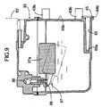
- auxiliary fuel tank/fuel pump assembly A is explained further in detail by reference to Figs. 6 to 9.
- a float 37a of the float valve 37 provided within the auxiliary fuel tank 35 is supported in a vertically swingable manner via a pivot shaft 38 that is parallel to the tilt shaft 58 and extends horizontally in the left-and-right direction.
- the auxiliary fuel tank 35 has a substantially rectangular shape and is positioned so that its left and right outer sides are perpendicular to the pivot shaft 38 and its front and rear outer end faces are vertical and substantially parallel to the pivot shaft 38.
- Projectingly and integrally provided on at least one of the left and right outer sides of the auxiliary fuel tank 35 (the right outer side 35a in the illustrated example) are a plurality of first mounting bosses 43a.
- auxiliary fuel tank 35 Projectingly and integrally provided on at least one of the front and rear outer end faces of the auxiliary fuel tank 35 (the front outer end face 35b in the illustrated example) are the same number of second mounting bosses 43b in the same arrangement as that of the first mounting bosses 43a.
- the secondary fuel pump 40 provided on the secondary fuel pump 40 are a plurality of connecting arms 47 that can be fixedly connected securely to either of the first or second mounting bosses 43a or 43b.
- first and second connecting bosses 44a and 44b Formed on lower parts of the outer faces of the auxiliary fuel tank 35 on which the first mounting bosses 43a and the second mounting bosses 43b have been formed, are first and second connecting bosses 44a and 44b to which the same suction pipe 42 of the secondary fuel pump 40 can be connected.
- a fuel outlet port 65 Formed in each of the connecting bosses 44a and 44b is a fuel outlet port 65 opening on the outer end face of the connecting boss.
- the inner end of the fuel outlet port 65 is blocked by a blocking wall 65a that is integral with the auxiliary fuel tank 35 such that a hole is formed through the blocking wall 65a when the corresponding boss 44a or 44b is connected to the suction pipe 42.
- An annular seal groove 45 is formed on the outer end of each of the connecting bosses 44a and 44b.
- a hole is first machined through the blocking wall 65a of the first connecting boss 44a so as to provide a connection to the fuel outlet port 65.
- the seal 46 is inserted in the seal groove 45 at the outer end of the first connecting boss 44a.
- the plurality of connecting arms 47 of the secondary fuel pump 40 are secured to the first mounting bosses 43a of the auxiliary fuel tank 35 by bolts 48.
- the second connecting boss 44b and the second mounting bosses 43b remain unused. Accordingly, the auxiliary fuel tank 35 and the secondary fuel pump 40 are connected so as to be aligned in the left-and-right direction to form the auxiliary fuel tank/fuel pump assembly A.
- the auxiliary fuel tank 35 is connected to stays 59 (see Fig. 3) rising from the upper face of the mount case 1 via appropriate support brackets 49.
- the auxiliary fuel tank/fuel pump assembly A in which the auxiliary fuel tank 35 and the secondary fuel pump 40 are connected so as to be aligned in the left-and-right direction, can be arranged in a reasonable manner in the space to the rear of the engine E 1 in the engine compartment 16, the space being particularly narrow in the front-and-rear direction, thereby enhancing the space efficiency and preventing any increase in the dimensions of the engine compartment 16 while avoiding interference between the assembly A and its neighboring members such as the engine hood 15, an engine part, or a pipeline.
- the pivot shaft 38 of the float valve 37 within the auxiliary fuel tank 35 is maintained parallel to the tilt shaft 58, the level of the stored fuel is always controlled at a constant level within the auxiliary fuel tank 35 by proper operation of the float valve 37, even when the outboard motor O 1 is tilted up.
- An outboard motor O 2 to which the second embodiment of the auxiliary fuel tank/fuel pump assembly A is applied includes an in-line multicylinder engine E 2 housed in an engine compartment 16 so that a cylinder head side faces rearward and a crankshaft 4 is vertical.
- the auxiliary fuel tank/fuel pump assembly A is arranged in a space on the left or right side of the engine E 2 in the engine compartment 16.
- a hole is first machined through in the blocking wall 65a of the fuel outlet port 65 in the second connecting boss 44b on the front outer end face 35b of the auxiliary fuel tank 35 so as to provide a connection to the fuel outlet port 65.
- the seal 46 is then inserted in the seal groove 45 at the outer end of the second connecting boss 44b.
- the plurality of connecting arms 47 of the secondary fuel pump 40 are secured to the second mounting bosses 43b on the front outer end face 35b of the auxiliary fuel tank 35 by bolts 48.
- the first connecting boss 44a and the first mounting bosses 43a remain unused. Accordingly, the auxiliary fuel tank 35 and the secondary fuel pump 40 are connected so as to be aligned in the front-and-rear direction to form the auxiliary fuel tank/fuel pump assembly A.
- the auxiliary fuel tank 35 is mounted on one outer side of the engine E 2 via appropriate support brackets 49'. For example. it is fixed to an intake manifold 71 placed along one side of a cylinder block 70.
- the auxiliary fuel tank/fuel pump assembly A in which the auxiliary fuel tank 35 and the secondary fuel pump 40 are joined in the front-and-rear direction can be arranged in a reasonable manner in the space to the side of the engine E 2 in the engine compartment 16, the space being particularly narrow in the left-and-right direction, thereby enhancing the space efficiency and avoiding interference between the assembly A and its neighboring members.
- the pivot shaft 38 of the float valve 37 within the auxiliary fuel tank 35 can be maintained parallel to the tilt shaft 58.
- auxiliary fuel tank/fuel pump assembly A in the first and second embodiments can use the identical auxiliary fuel tank 35 and the identical fuel pump 40, the mass-productivity of the auxiliary fuel tank 35 is improved and the overall cost of the assembly A can be reduced.
- the auxiliary fuel tank 35 may have one connecting pipe having a permanently open fuel outlet port 65, and the connecting pipe can be connected to the suction pipe 42 of the secondary fuel pump 40 via a flexible fuel pipe.
Landscapes
- Engineering & Computer Science (AREA)
- Chemical & Material Sciences (AREA)
- Combustion & Propulsion (AREA)
- Mechanical Engineering (AREA)
- Ocean & Marine Engineering (AREA)
- General Engineering & Computer Science (AREA)
- Cooling, Air Intake And Gas Exhaust, And Fuel Tank Arrangements In Propulsion Units (AREA)
Applications Claiming Priority (2)
| Application Number | Priority Date | Filing Date | Title |
|---|---|---|---|
| JP2001215219 | 2001-07-16 | ||
| JP2001215219A JP4021163B2 (ja) | 2001-07-16 | 2001-07-16 | 船外機用の副燃料タンク・燃料ポンプ組立体 |
Publications (3)
| Publication Number | Publication Date |
|---|---|
| EP1277935A2 true EP1277935A2 (de) | 2003-01-22 |
| EP1277935A3 EP1277935A3 (de) | 2003-08-13 |
| EP1277935B1 EP1277935B1 (de) | 2007-09-12 |
Family
ID=19049899
Family Applications (1)
| Application Number | Title | Priority Date | Filing Date |
|---|---|---|---|
| EP02015655A Expired - Lifetime EP1277935B1 (de) | 2001-07-16 | 2002-07-16 | Zusammenbau von Brennstoffbehälter- und pumpe für einen Aussenbordmotor |
Country Status (5)
| Country | Link |
|---|---|
| US (1) | US6616490B2 (de) |
| EP (1) | EP1277935B1 (de) |
| JP (1) | JP4021163B2 (de) |
| CA (1) | CA2393856C (de) |
| DE (1) | DE60222342T2 (de) |
Families Citing this family (2)
| Publication number | Priority date | Publication date | Assignee | Title |
|---|---|---|---|---|
| US9695764B1 (en) | 2015-02-10 | 2017-07-04 | Brunswick Corporation | Multi-fuel marine engine control system |
| JP2024066552A (ja) * | 2022-11-02 | 2024-05-16 | ヤマハ発動機株式会社 | 船外機および船舶 |
Citations (1)
| Publication number | Priority date | Publication date | Assignee | Title |
|---|---|---|---|---|
| JPH10184375A (ja) | 1996-12-19 | 1998-07-14 | Honda Motor Co Ltd | エンジンの燃料供給構造 |
Family Cites Families (7)
| Publication number | Priority date | Publication date | Assignee | Title |
|---|---|---|---|---|
| US5375578A (en) * | 1992-03-05 | 1994-12-27 | Sanshin Kogyo Kabushiki Kaisha | High pressure fuel feeding device for fuel injection engine |
| JPH10131821A (ja) * | 1996-10-28 | 1998-05-19 | Sanshin Ind Co Ltd | 船舶用エンジンの燃料供給装置 |
| JP3871751B2 (ja) * | 1996-12-19 | 2007-01-24 | 本田技研工業株式会社 | 船外機におけるサブタンクのエアベント構造 |
| JP3784508B2 (ja) * | 1997-09-12 | 2006-06-14 | 本田技研工業株式会社 | パワーユニットにおける補助燃料タンクのエアベント装置 |
| JP3866388B2 (ja) * | 1997-09-24 | 2007-01-10 | 本田技研工業株式会社 | 船外機における補助燃料タンクの冷却装置 |
| US6390871B1 (en) * | 2001-03-07 | 2002-05-21 | Brunswick Corporation | Fuel reservoir mounted to a driveshaft housing of an outboard motor |
| US6527603B1 (en) * | 2001-03-07 | 2003-03-04 | Brunswick Corporation | Fuel delivery system for a marine propulsion device |
-
2001
- 2001-07-16 JP JP2001215219A patent/JP4021163B2/ja not_active Expired - Fee Related
-
2002
- 2002-07-16 CA CA002393856A patent/CA2393856C/en not_active Expired - Fee Related
- 2002-07-16 US US10/195,549 patent/US6616490B2/en not_active Expired - Lifetime
- 2002-07-16 EP EP02015655A patent/EP1277935B1/de not_active Expired - Lifetime
- 2002-07-16 DE DE60222342T patent/DE60222342T2/de not_active Expired - Lifetime
Patent Citations (1)
| Publication number | Priority date | Publication date | Assignee | Title |
|---|---|---|---|---|
| JPH10184375A (ja) | 1996-12-19 | 1998-07-14 | Honda Motor Co Ltd | エンジンの燃料供給構造 |
Also Published As
| Publication number | Publication date |
|---|---|
| EP1277935A3 (de) | 2003-08-13 |
| CA2393856C (en) | 2005-03-15 |
| DE60222342D1 (de) | 2007-10-25 |
| DE60222342T2 (de) | 2008-06-12 |
| CA2393856A1 (en) | 2003-01-16 |
| JP2003028016A (ja) | 2003-01-29 |
| EP1277935B1 (de) | 2007-09-12 |
| US20030045186A1 (en) | 2003-03-06 |
| US6616490B2 (en) | 2003-09-09 |
| JP4021163B2 (ja) | 2007-12-12 |
Similar Documents
| Publication | Publication Date | Title |
|---|---|---|
| EP0957258B1 (de) | Belüftung eines zwischentanks in motoren | |
| EP1277935B1 (de) | Zusammenbau von Brennstoffbehälter- und pumpe für einen Aussenbordmotor | |
| US6672287B2 (en) | Fuel rail/fuel conduit connecting structure in engine of outboard engine system | |
| JPH10220245A (ja) | バーチカルクランク軸型エンジン | |
| JP4076617B2 (ja) | 小型船舶の吸気装置 | |
| JP3970554B2 (ja) | 水冷v型エンジン船外機 | |
| EP0902176B1 (de) | Belüftungsvorrichtung für einen Hilfsbehälter in einer Krafteinheit | |
| US20240359784A1 (en) | Outboard engine assembly having an idle relief system | |
| JP3833316B2 (ja) | 船舶用エンジンの燃料供給装置 | |
| JPH10339159A (ja) | 船舶用エンジンの燃料供給装置 | |
| US7121907B2 (en) | Anode mounting structure for outboard motor engine | |
| EP1233172A2 (de) | Ansaugsystem für einen Viertakt-Aussenbordmotor in V-Anordnung | |
| EP2615290B1 (de) | Kraftstoffzufuhrsystem eines Außenbordmotors | |
| JP3416285B2 (ja) | 船外機の燃料供給装置 | |
| JP3853892B2 (ja) | 船外機用多気筒エンジンの燃料供給構造 | |
| US12534169B2 (en) | Outboard motor and boat | |
| JP2002242771A (ja) | エンジンの吸気マニホールド | |
| JP4464571B2 (ja) | エンジンの吸気マニホールド | |
| US6032633A (en) | Vertical crankshaft engine for outboard marine engines | |
| JP2002339824A (ja) | エンジンの燃料供給装置 | |
| JP2002242777A (ja) | 船外機における吸気及び燃料系の配設構造 | |
| JP3450458B2 (ja) | 2サイクルエンジンの燃料供給装置 | |
| JP2003074345A (ja) | 水冷v型エンジン船外機 | |
| JPH10131823A (ja) | 船舶用エンジンの燃料供給装置 | |
| JPH07174030A (ja) | エンジン |
Legal Events
| Date | Code | Title | Description |
|---|---|---|---|
| PUAI | Public reference made under article 153(3) epc to a published international application that has entered the european phase |
Free format text: ORIGINAL CODE: 0009012 |
|
| AK | Designated contracting states |
Kind code of ref document: A2 Designated state(s): AT BE BG CH CY CZ DE DK EE ES FI FR GB GR IE IT LI LU MC NL PT SE SK TR |
|
| AX | Request for extension of the european patent |
Free format text: AL;LT;LV;MK;RO;SI |
|
| PUAL | Search report despatched |
Free format text: ORIGINAL CODE: 0009013 |
|
| AK | Designated contracting states |
Designated state(s): AT BE BG CH CY CZ DE DK EE ES FI FR GB GR IE IT LI LU MC NL PT SE SK TR |
|
| AX | Request for extension of the european patent |
Extension state: AL LT LV MK RO SI |
|
| 17P | Request for examination filed |
Effective date: 20030827 |
|
| AKX | Designation fees paid |
Designated state(s): DE GB SE |
|
| GRAP | Despatch of communication of intention to grant a patent |
Free format text: ORIGINAL CODE: EPIDOSNIGR1 |
|
| GRAS | Grant fee paid |
Free format text: ORIGINAL CODE: EPIDOSNIGR3 |
|
| GRAA | (expected) grant |
Free format text: ORIGINAL CODE: 0009210 |
|
| AK | Designated contracting states |
Kind code of ref document: B1 Designated state(s): DE GB SE |
|
| REG | Reference to a national code |
Ref country code: GB Ref legal event code: FG4D |
|
| REF | Corresponds to: |
Ref document number: 60222342 Country of ref document: DE Date of ref document: 20071025 Kind code of ref document: P |
|
| REG | Reference to a national code |
Ref country code: SE Ref legal event code: TRGR |
|
| PLBE | No opposition filed within time limit |
Free format text: ORIGINAL CODE: 0009261 |
|
| STAA | Information on the status of an ep patent application or granted ep patent |
Free format text: STATUS: NO OPPOSITION FILED WITHIN TIME LIMIT |
|
| 26N | No opposition filed |
Effective date: 20080613 |
|
| REG | Reference to a national code |
Ref country code: DE Ref legal event code: R082 Ref document number: 60222342 Country of ref document: DE Representative=s name: MITSCHERLICH, PATENT- UND RECHTSANWAELTE PARTM, DE Ref country code: DE Ref legal event code: R081 Ref document number: 60222342 Country of ref document: DE Owner name: HONDA GIKEN KOGYO K.K., JP Free format text: FORMER OWNERS: KEIHIN CORP., TOKIO/TOKYO, JP; HONDA GIKEN KOGYO K.K., TOKYO, JP |
|
| PGFP | Annual fee paid to national office [announced via postgrant information from national office to epo] |
Ref country code: DE Payment date: 20170711 Year of fee payment: 16 Ref country code: GB Payment date: 20170712 Year of fee payment: 16 |
|
| REG | Reference to a national code |
Ref country code: GB Ref legal event code: 732E Free format text: REGISTERED BETWEEN 20171012 AND 20171018 |
|
| PGFP | Annual fee paid to national office [announced via postgrant information from national office to epo] |
Ref country code: SE Payment date: 20170711 Year of fee payment: 16 |
|
| REG | Reference to a national code |
Ref country code: DE Ref legal event code: R119 Ref document number: 60222342 Country of ref document: DE |
|
| GBPC | Gb: european patent ceased through non-payment of renewal fee |
Effective date: 20180716 |
|
| PG25 | Lapsed in a contracting state [announced via postgrant information from national office to epo] |
Ref country code: GB Free format text: LAPSE BECAUSE OF NON-PAYMENT OF DUE FEES Effective date: 20180716 Ref country code: DE Free format text: LAPSE BECAUSE OF NON-PAYMENT OF DUE FEES Effective date: 20190201 |
|
| PG25 | Lapsed in a contracting state [announced via postgrant information from national office to epo] |
Ref country code: SE Free format text: LAPSE BECAUSE OF NON-PAYMENT OF DUE FEES Effective date: 20180717 |