EP1274102B1 - Polymercompound mit nichtlinearer Strom-Spannungs-Kennlinie und Verfahren zur Herstellung eines Polymercompounds - Google Patents
Polymercompound mit nichtlinearer Strom-Spannungs-Kennlinie und Verfahren zur Herstellung eines Polymercompounds Download PDFInfo
- Publication number
- EP1274102B1 EP1274102B1 EP01810645A EP01810645A EP1274102B1 EP 1274102 B1 EP1274102 B1 EP 1274102B1 EP 01810645 A EP01810645 A EP 01810645A EP 01810645 A EP01810645 A EP 01810645A EP 1274102 B1 EP1274102 B1 EP 1274102B1
- Authority
- EP
- European Patent Office
- Prior art keywords
- polymer compound
- polymer
- filler
- compound according
- voltage
- Prior art date
- Legal status (The legal status is an assumption and is not a legal conclusion. Google has not performed a legal analysis and makes no representation as to the accuracy of the status listed.)
- Expired - Lifetime
Links
Images

Classifications
-
- H—ELECTRICITY
- H01—ELECTRIC ELEMENTS
- H01C—RESISTORS
- H01C7/00—Non-adjustable resistors formed as one or more layers or coatings; Non-adjustable resistors made from powdered conducting material or powdered semi-conducting material with or without insulating material
- H01C7/10—Non-adjustable resistors formed as one or more layers or coatings; Non-adjustable resistors made from powdered conducting material or powdered semi-conducting material with or without insulating material voltage responsive, i.e. varistors
- H01C7/105—Varistor cores
- H01C7/108—Metal oxide
- H01C7/112—ZnO type
Definitions
- the invention is based on a polymer compound according to the preamble of patent claim 1 and of a process for the preparation of a polymer compound according to the preamble of claim 14.
- the polymer compound contains a polymer matrix in which as filler electrically conductive particles such as conductivity black and / or metal powder and / or electrically semiconductive particles, such as SiC or ZnO are embedded.
- This polymer compound has a non-linear current-voltage characteristic which is influenced by the filler content and the dispersion of the filler.
- the specific resistance and other electrical properties determined by the current-voltage characteristic can generally be influenced only by the filler content and the degree of dispersion, depending on the strength of an electric field applied to the polymer compound.
- the polymer compound can be used with advantage as the base material in voltage-limiting resistors (varistors) or as a field-controlling material in energy systems and apparatus, in particular in cable terminations or in cable connection sleeves.
- a polymer compound of the type mentioned in the introduction and a method of the type mentioned in the introduction are described in an article by R. Strümpler et al. "Smart Varistor Composites” Proc.of the 8 th CIMTEC Ceramic Congress. June 1994 as well as in EP 875 087 B1 and WO 99/56290 A1 described.
- As filler doped and sintered particles of zinc oxide are provided in this polymer compound.
- Typical dopants are metals as used in the preparation of metal oxide varistors and typically include Bi, Cr, Co, Mn and Sb.
- Doped ZnO powder is sintered at 800 to 1300 ° C. By suitably sized sintering temperatures and times, desired electrical properties of the filler are achieved. After sintering, each particle has an electrical conductivity, which changes non-linearly in the course of an applied electric field. Each particle therefore acts as a small varistor. Due to the appropriately sized sintering conditions, the nonlinear behavior of the filler can be adjusted within certain limits. The non-linear electrical properties of the polymer compound can therefore be adjusted during the preparation of the compound not only by the filler content and the degree of dispersion, but also by the sintering conditions of the filler.
- An in EP 0 576 836 A described current-limiting resistor consists of a polymeric matrix and two embedded in the matrix fillers, the first of which contains electrically conductive particles in the form of carbon, metal or a boride, silicide, oxide or carbide in doped or undoped form, while the second filler a doped semiconductive ceramic, such as based on ZnO, a metal granules, an electrically conductive plastic or fibers contains.
- Polymer matrix and first filler form a first resistance material with a lower cold resistance than a second resistance material formed from the polymer matrix and the second filler.
- the first and possibly also the second resistance material are characterized by PTC behavior and then both have a nonlinear current-voltage characteristic on
- the invention has for its object to provide a polymer compound of the type mentioned, its non-linear electrical properties can be adjusted easily during the manufacturing process and to provide a method for producing such a polymer compound, with which polymer compounds with predetermined non-linear electrical properties can be produced in an economical manner
- the polymer compound according to the invention is characterized in that the filler contains at least two filler components with differing non-linear current-voltage characteristics, and that the two filler components are each formed by a doped, sintered metal oxide with grain boundary-containing particles and differ from each other by deviating stoichiometry Dopants and / or by divergent, caused by different sintering grain boundary structures.
- polymer compound having a nonlinear current-voltage characteristic other than these two characteristics can be achieved.
- the polymer compound according to the invention is therefore distinguished by the fact that it can be produced with little effort despite precisely defined non-linear electrical properties.
- Polymer compounds with virtually any arbitrary current-voltage characteristics can be produced from a small base set of filler components each with a defined non-linear current-voltage characteristic become.
- the polymer compound can not only be given predetermined electrical properties, but also its thermal conductivity can be decisively influenced. This is particularly important when using polymer compounds as field control material, for example in cable fittings, because the cable fittings are heavily heated because of dielectric losses in the polymer compound and because of electrical losses in the metallic conductor.
- the generally low thermal conductivity of the polymer is offset by suitably selected filler components, which in addition to the good electrical behavior also give the polymer compound sufficiently good thermal conductivity.
- the two filler components are each formed by a doped, sintered metal oxide with grain boundary-containing particles and differ from each other by deviating stoichiometry of the dopants and / or by divergent, caused by different sintering conditions grain boundary structures with different grain sizes.
- the metal oxide is generally zinc oxide, but may advantageously be tin dioxide or titanium dioxide.
- the differing current-voltage characteristics can be achieved by different weight proportions of the dopants, i. by different formulations of the two filler components or by different conditions during sintering of the filler components.
- the sintering conditions include above all the sintering temperature, the residence time, the gas composition of the sintering atmosphere and the heating and cooling rates.
- the conductivity of powdered zinc oxide doped with a plurality of metals can be increased at a given electric field strength.
- the polymer compound may contain electrically conductive or electrically semiconducting material, such as conductivity black or metal powder. Above all, this material makes better contacting of the individual particles of the non-linear achieved electrical behavior exhibiting filler components. The energy absorption of the polymer compound is significantly increased.
- a surge arrester containing a polymer compound according to the invention is then distinguished by a high pulse strength. In order to achieve a sufficient effect, the proportion of additional component should be 0.01 to 15 percent by volume of the polymer compound.
- the additional component contains particles with a large length-to-diameter ratio, in particular nanotubes. If the polymer matrix is oriented in a preferred direction by injection molding, for example, during the production of the polymer compound, these particles can be oriented in the preferred direction because of the large length-to-diameter ratio, and thus a polymer compound with anisotropic electrical properties can be achieved in a simple manner. Such a material can be advantageously used to solve field control tasks in cable connection sleeves or in cable terminations.
- the polymer compound has a high dielectric constant.
- the polymer compound according to the invention can then easily control an electric field.
- Such a field control can relate, for example, to the homogenization of the distribution of electrical fields of energy-technical installations or apparatuses in normal operation.
- the field-controlling function of the polymer according to the invention can be improved in that the filler has an additional component of a material with a high dielectric constant.
- additional components are, for example, BaTiO 3 or TiO 2 .
- the polymer matrix typically contains a single polymer or a mixture of polymers.
- the dielectric behavior of the polymer compound can be further improved if the individual polymer or at least one of the polymers of the mixture contains polar groups and / or is an intrinsically electrically conductive polymer.
- a typical polymer having polar groups is, for example, a polyamide.
- the proportion of polar group-containing polymer and / or intrinsically electrically conductive polymer is advantageously 0.01 to 50 volume percent of the polymer matrix.
- the polymer compound may additionally be provided an additive which contains at least one stabilizer, a flame retardant and / or a processing aid.
- the proportion of this additive may be between 0.01 to 5 volume percent of the polymer compound.
- a flame-retardant polymer compound can be produced particularly economically if it contains aluminum and / or magnesium hydroxide which acts as a flame retardant. Since, for reasons of flame retardance, the polymer matrix in many cases must not fall below a predefined LOI (limited oxygen index) value (the smaller the LOI value, the easier it is for the polymer compound to burn), the use of the inexpensive hydroxides makes it possible to use the LOI Value can be increased in a very cost-effective manner.
- LOI limited oxygen index
- adhesion promoter A good mechanical strength, the polymer compound, then, if in addition a bonding between polymer and filler enhancing adhesion promoter is provided.
- the proportion of adhesion promoter should be between 0.01 to 5 percent by volume of the polymer compound.
- the adhesion promoter which is preferably formed as a silane, firmly couples the polymer matrix to the filler. Cracking in the polymer compound due to lack of adhesion of the polymer matrix to the filler and thereby initiated material fracture is thus avoided with great certainty.
- the adhesion promoter substantially improves the electrical properties of the polymer compound according to the invention.
- the filler is mixed from a base set of at least two filler components with differing non-linear current-voltage characteristics.
- the mixing ratio of the components becomes so selected that the polymer compound has the predetermined characteristic.
- the polymer compound can now be produced in a simple and economical manner without extensive preliminary investigations.
- the mixing ratio is selected from a predetermined characteristic field of polymer compounds, of which two each contain at most one of the at least two filler components and at least one further containing at least two mixed with a predetermined ratio filler components.
- Varistor powders R1, R2, S1 and S2 have been prepared by known processes described for example in the introductory cited prior art.
- the powders contained as the major constituent (greater than 90 mole percent) sintered zinc oxide doped with additives, predominantly Sb, Bi, Co, Mn and Cr, (less than 10 mole percent in total).
- the varistor powder R1 had a smaller bismuth content than the varistor powder R2.
- the powders R1 and R2 were produced under the same sintering conditions, namely by sintering at about 1100 ° C in a ceramic tube of a rotary kiln.
- the powders S1 and S2 had the same composition but were prepared under different sintering conditions.
- the powder S1 was produced by a continuous sintering process in a rotary kiln at a maximum sintering temperature of about 1070 ° C, the powder S2 in a batch furnace at maximum sintering temperature of about 1200 ° C and a residence time of the batch in the oven of about 18 hours.
- Sieving, with optional milling, limited the particle sizes of the powders to values typically between 32 and 125 microns.
- Oil was used as the matrix material, since test specimens could thus be produced in a particularly simple manner. Instead of oil, however, it is also possible to use a duromer, an elastomer, a thermoplastic, a copolymer, a thermoplastic elastomer or a gel or a mixture of at least two of these substances.
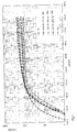
- a variable DC voltage source was applied to the two electrodes. By varying the level of the DC voltage, the electric field E [V / mm] acting in the associated specimen was adjusted and that in the specimen flowing current measured. The current density J [A / cm 2 ] was used to determine the current density FIGS. 1 and 2 Obtained DC current-voltage characteristics.
- the fillers S73 and S37 formed by mixing the filler components S1 and S2 produced by different sintering conditions lead to test specimens whose DC current-voltage characteristics belong to a family of characteristics which of the two characteristic curves S1 and S2 filled specimens is limited.
- By changing the mixing ratio of the two filler components specimens were achieved with characteristics that lie between the two limiting characteristics with these fillers in a simple manner.
- the mixing ratio can be determined from a family of characteristics determined in a corresponding manner for polymer compounds.
- the filler is prepared and the desired polymer compound is prepared by mixing the filler with polymer, for example silicone.
- polymer compounds with fillers which are achieved by mixing the filler components R1 or R2 and S1 or S2 or by mixing three or four of these filler components.
- the filler components need not necessarily be formed from ZnO powder. You can also use another powdered material with non-linear current-voltage characteristics, such as doped silicon carbide, tin dioxide or titanium dioxide.
- the electrical conductivity of the polymer compound can be increased by several orders of magnitude in the range of small electrical field strengths, and thus a polymer with a flat DC-voltage-voltage characteristic can be achieved.
Description
- Bei der Erfindung wird ausgegangen von einem Polymercompound nach dem Oberbegriff von Patentanspruch 1 sowie von einem Verfahren zur Herstellung eines Polymercompounds nach dem Oberbegriff von Patentanspruch 14. Der Polymercompound enthält eine Polymermatrix, in die als Füllstoff elektrisch leitende Teilchen, wie Leitfähigkeitsruss und/oder Metallpulver und/oder elektrisch halbleitende Teilchen, wie etwa SiC oder ZnO, eingebettet sind. Dieser Polymercompound weist eine nichtlineare Strom-Spannungs-Kennlinie auf, welche vom Füllstoffgehalt und der Dispersion des Füllstoffs beeinflusst wird. Der durch die Strom-Spannungs-Kennlinie bestimmte spezifische Widerstand und andere elektrische Eigenschaften können in Abhängigkeit von der Stärke eines am Polymercompound anliegenden elektrischen Feldes im allgemeinen nur über den Füllstoffgehalt und den Dispersionsgrad beeinflusst werden.
- Der Polymercompound kann mit Vorteil als Basismaterial in spannungsbegrenzenden Widerständen (Varistoren) eingesetzt werden oder als feldsteuerndes Material in energietechnischen Anlagen und Apparaten, wie insbesondere in Kabelendverschlüssen oder in Kabelverbindungsmuffen.
- Ein Polymercompound der eingangs genannten Art und ein Verfahren der eingangs genannten Art sind in einem Aufsatz von R. Strümpler et al. "Smart Varistor Composites" Proc.of the 8th CIMTEC Ceramic Congress. June 1994 sowie in
EP 875 087 B1 WO 99/56290 A1 - Typische Dotierstoffe sind Metalle, wie sie bei der Herstellung von Metalloxid-Varistoren verwendet werden und typischerweise Bi, Cr, Co, Mn und Sb umfassen Dotiertes ZnO-Pulver wird bei 800 bis 1300°C gesintert. Durch geeignet bemessene Sintertemperaturen und -zeiten werden erwünschte elektrische Eigenschaften des Füllstoffs erreicht. Nach dem Sintern weist jedes Teilchen eine elektrische Leitfähigkeit auf, welche sich in Abgängigkeit von einem angelegten elektrischen Feld nichtlinear ändert Jedes Teilchen wirkt daher als kleiner Varistor. Durch die geeignet bemessenen Sinterbedingungen kann das nichtlineare Verhalten des Füllstoffs innerhalb bestimmter Grenzen eingestellt werden. Die nichtlinearen elektrischen Eigenschaften des Polymercompounds können daher während der Herstellung des Compounds nicht nur über den Füllstoffgehalt und den Dispersionsgrad sondern auch über die Sinterbedingungen des Füllstoffs eingestellt werden.
- Ein in
EP 0 576 836 A beschriebener strombegrenzender Widerstand besteht aus einer polymeren Matrix und zwei in die Matrix eingebetteten Füllstoffen, von denen der erste elektrisch leitende Teilchen in Form von Kohlenstoff, Metall oder eines Borids, Silizids, Oxids oder Carbids jeweils in dotierter oder undotierter Form enthält, während der zweite Füllstoff eine dotierte halbleitende Keramik, etwa auf der Basis ZnO, ein Metallgranulat, einen elektrisch leitend gemachten Kunststoff oder Fasern enthält. Polymermatrix und erster Füllstoff bilden ein erstes Widerstandsmaterial mit einem geringeren Kaltwiderstand als ein aus der Polymermatrix und dem zweiten Füllstoff gebildetes zweites Widerstandsmaterial Das erste und gegebenenfalls auch das zweite Widerstandsmaterial zeichnen sich durch PTC-Verhalten aus und weisen dann beide eine nichtlineare Strom-Spannungs-Kennlinie auf -
DE 23 63 172 A zeigt einen spannungsabhängigen Widerstand, der durch Sintern zweier unterschiedlich dotierter Komponenten mit voneinander stark abweichender elektrischer Leitfähigkeit gefertigt wurde. - Der Erfindung, wie sie in den Patentansprüchen angegeben ist, liegt die Aufgabe zugrunde, einen Polymercompound der eingangs genannten Art zu schaffen, dessen nichtlinearen elektrischen Eigenschaften während des Herstellprozesses in einfacher Weise eingestellt werden können und ein Verfahren zur Herstellung eines solchen Polymercompounds anzugeben, mit dem in wirtschaftlicher Weise Polymercompounds mit vorgegebenen nichtlinearen elektrischen Eigenschaften gefertigt werden können
- Der erfindungsgemässe Polymercompound ist dadurch gekennzeichnet, dass der Füllstoff mindestens zwei Füllstoffkomponenten enthält mit voneinander abweichenden nichtlinearen Strom-Spannungs-Kennlinien, und dass die beiden Füllstoffkomponenten jeweils von einem dotierten, gesinterten Metalloxid mit Korngrenzen enthaltenden Teilchen gebildet sind und sich voneinander unterscheiden durch abweichende Stöchiometrie der Dotierstoffe und/oder durch voneinander abweichende, durch unterschiedliche Sinterbedingungen hervorgerufene Komgrenzenstrukturen.
- Durch Auswahl geeignet bemessener Mengen dieser Füllstoffkomponenten kann so ein Polymercompound mit einer von diesen beiden Kennlinien abweichenden nichtlinearen Strom-Spannungs-Kennlinie erreicht werden. Der erfindungsgemässe Polymercompound zeichnet sich daher dadurch aus, dass er trotz genau definierter nichtlinearer elektrischer Eigenschaften mit geringem Aufwand hergestellt werden kann Aus einem kleinen Basissatz an Füllstoffkomponenten jeweils mit definierter nichtlinearer Strom-Spannungs-Kennlinie können Polymercompounds mit nahezu beliebig ausgebildeten Strom-Spannungs-Kennlinien gefertigt werden.
- Durch die Kombination der beiden Füllstoffkomponenten können dem Polymercompound nicht nur vorbestimmte elektrische Eigenschaften verliehen werden, es kann dadurch auch dessen Wärmeleitfähigkeit ganz entscheidend beeinflusst werden. Bei der Verwendung von Polymercompounds als Feldsteuermaterial etwa in Kabelgarnituren ist dies besonders wichtig, da wegen dielektrischer Verluste im Polymercompound und wegen elektrischer Verluste im metallischen Leiter die Kabelgarnitur stark erwärmt wird. Die im allgemeinen geringe Wärmeleitfähigkeit des Polymers wird aufgehoben durch geeignet ausgewählte Füllstoffkomponenten, welche neben dem guten elektrischen Verhalten dem Polymercompound auch ausreichend gute Wärmeleitfähigkeit geben.
- Bei Anwendungen des Polymercompounds, bei denen wie bei Überspannungsableitern oder Feldsteuermaterial nichtlineares elektrisches Verhalten im Vordergrund steht, ist es besonders vorteilhaft, wenn die beiden Füllstoffkomponenten jeweils von einem dotierten, gesinterten Metalloxid mit Korngrenzen enthaltenden Teilchen gebildet sind und sich voneinder unterscheiden durch abweichende Stöchiometrie der Dotierstoffe und/oder durch voneinander abweichende, durch unterschiedliche Sinterbedingungen hervorgerufene Korngrenzenstrukturen mit unterschiedlichen Korngrössen. Das Metalloxid ist im allgemeinen Zinkoxid, kann mit Vorteil aber auch Zinndioxid oder Titandioxid sein. Die voneinander abweichenden Strom-Spannungs-Kennlinien können erreicht werden durch unterschiedliche Gewichtsanteile der Dotierstoffe, d.h. durch unterschiedliche Rezepturen der beiden Füllstoffkomponenten oder durch unterschiedlich Bedingungen beim Sintern der Füllstoffkomponenten. Die Sinterbedingungen umfassen vor allem die Sintertemperatur, die Verweildauer, die Gaszusammensetzung der Sinteratmosphäre sowie die Aufheiz- und Abkühlraten. Im allgemeinen kann durch Erhöhen der Sintertemperatur die Leitfähigkeit von mit mehreren Metallen dotiertem pulverförmigem Zinkoxid bei einer vorgegebenen elektrischen Feldstärke erhöht werden.
- Um die Strom-Spannungs-Kennlinie zu verändern, kann der Polymercompound elektrisch leitendes oder elektrisch halbleitendes Material, wie etwa Leitfähigkeitsruss oder Metallpulver, enthalten. Durch dieses Material wird vor allem aber eine bessere Kontaktierung der einzelnen Teilchen der nichtlineares elektrisches Verhalten aufweisenden Füllstoffkomponenten erreicht. Die Energieaufnahme des Polymercompounds wird so wesentlich erhöht. Ein einen erfindungsgemässen Polymercompound enthaltender Überspannungsableiter zeichnet sich dann durch eine hohe Impulsfestigkeit aus. Um eine ausreichende Wirkung zu erreichen, sollte der Anteil an Zusatzkomponente 0,01 bis 15 Volumenprozent des Polymercompounds betragen.
- Zur Lösung feldsteuernder Aufgaben ist es von besonderem Vorteil, wenn die Zusatzkomponente Teilchen mit einem grossen Länge-zu-Durchmesser-Verhältnis enthält, wie insbesondere Nanotubes. Wird die Polymermatrix bei der Herstellung des Polymercompounds etwa durch Spritzgiessen in einer Vorzugsrichtung ausgerichtet, so könnnen wegen des grossen Länge-zu-Durchmesser-Verhältnisses diese Teilchen in Vorzugsrichtung orientiert und so in einfacher Weise ein Polymercompound mit anisotropen elektrische Eigenschaften erreicht werden. Ein solches Material kann mit Vorteil zur Lösung von Feldsteueraufgaben in Kabelverbindungsmuffen oder in Kabelendverschlüssen eingesetzt werden.
- Wird als Füllstoff dotiertes Metalloxid, wie etwa dotiertes Zinkoxid eingesetzt, so weist der Polymercompound eine hohe Dielektrizitätszahl auf. Der erfindungsgemässe Polymercompound kann dann in einfacher Weise ein elektrisches Feld steuern. Ein solche Feldsteuerung kann beispielsweise die Homogenisierung der Verteilung elektrischer Felder energietechnischer Anlagen oder Apparate im Normalbetrieb betreffen. Die feldsteuernde Funktion des erfindungsgemässen Polymers kann dadurch verbessert werden, dass der Füllstoff eine Zusatzkomponente aufweist aus einem Material mit einer hohen Dielektrizitätszahl. Solche Zusatzkomponenten sind beispielsweise BaTiO3 oder TiO2.
- Die Polymermatrix enthält typischerweise ein einzelnes Polymer oder ein Gemisch von Polymeren. Das dielektrische Verhalten des Polymercompounds kann dadurch weiter verbessert werden, wenn das einzelne Polymer oder mindestens eines der Polymere des Gemischs polare Gruppen enthält und/oder ein intrinsisch elektrisch leitfähiges Polymer ist. Ein typisches Polymer mit polaren Gruppen ist zum Beispiel ein Polyamid. Der Anteil an polare Gruppen enthaltendem Polymer und/oder intrinsisch elektrisch leitfähigem Polymer beträgt mit Vorteil 0,01 bis 50 Volumenprozent der Polymermatrix.
- Im Polymercompound kann zusätzlich ein Additiv vorgesehen sein, welches mindestens einen Stabilisator, ein Flammschutzmittel und/oder ein Verarbeitungshilfsmittel enthält. Der Anteil dieses Additivs kann zwischen 0,01 bis 5 Volumenprozent des Polymercompounds betragen.
- Ein flammgeschützter Polymercompound kann dann besonders wirtschaftlich gefertigt werden, wenn er als Flammschutzmittel wirkendes Aluminium- und/oder Magnesiumhydroxid enthält. Da aus Gründen des Flammschutzes die Polymermatrix in vielen Fällen einen vorgegebenen LOI (Limited Oxygen Index)-Wert nicht unterschreiten darf (je kleiner der LOI-Wert, umso leichter kann der Polymercompound brennen), kann durch den Einsatz der preiswert erhältlichen Hydroxide der LOI-Wert in äusserst kostengünstiger Weise erhöht werden.
- Eine gute mechanische Festigkeit weist der Polymercompound dann auf, wenn zusätzlich ein die Haftung zwischen Polymer und Füllstoff erhöhender Haftvermittler vorgesehen ist. Der Anteil an Haftvermittler sollte zwischen 0,01 bis 5 Volumenprozent des Polymercompounds betragen. Der Haftvermittler, welcher vorzugsweise als Silan ausgebildet ist, koppelt die Polymermatrix fest an den Füllstoff an. Rissbildung im Polymercompound aufgrund mangelnder Haftung der Polymermatrix am Füllstoff und dadurch eingeleiteter Materialbruch wird so mit grosser Sicherheit vermieden. Zugleich verbessert der Haftvermittler die elektrischen Eigenschaften des erfindungsgemässen Polymercompounds ganz wesentlich. Dies vor allem deswegen, da durch die verbesserte Haftung die Bildung kleiner Hohlräume im Polymercompound vermieden und so das Risiko des Auftretens unerwünschten Teilentladungen bei der Einwirkung eines starken elektrischen Feldes ganz wesentlich reduziert wird. Diese Wirkung ist besonders vorteilhaft bei einem Polymercompound auf der Basis eines elastomeren Polymers, so wie er etwa als Feldsteuerelement für Kabelendverschlüsse oder Kabelverbindungsmuffen eingesetzt wird, da dann der Compound stark verformt werden kann, ohne dass unerwünschte Hohlraum- oder Rissbildung auftritt.
- Beim erfindungsgemässen Verfahren zur Herstellung eines Polymercompounds wird der Füllstoff aus einem Basissatz von mindestens zwei Füllstoffkomponenten mit voneinander abweichenden nichtlinearen Strom-Spannungs-Kennlinien gemischt. Hierbei wird das Mischungsverhältnis der Komponenten derart ausgewählt, dass das Polymercompound die vorbestimmte Kennlinie aufweist. Der Polymercompound kann nun ohne umfangreiche Voruntersuchungen in einfacher und wirtschaftlicher Weise gefertigt werden. Für eine besonders einfache Fertigung empfiehlt es sich, dass das Mischungsverhältnis ausgewählt wird aus einem vorbestimmten Kennlinienfeld von Polymercompounds, von denen zwei jeweils höchstens eine der mindestens zwei Füllstoffkomponenten enthalten und mindestens ein weiterer die mindestens zwei mit einem vorgegebenen Verhältnis gemischten Füllstoffkomponenten.
- Anhand von Zeichnungen werden Ausführungsbeispiele der Erfindung erläutert. Hierbei zeigen alle Figuren DC-Strom-Spannungs-Kennlinien von Polymercompounds nach dem Stand der Technik und nach der Erfindung (Kennlinienfelder).
- Nach bekannten, beispielsweise im einleitend genannten Stand der Technik beschriebenen Verfahren wurden Varistorpulver R1, R2, S1 und S2 hergestellt. Die Pulver enthielten als Hauptbestandteil (mehr als 90 Molprozent) gesintertes Zinkoxid, welches mit Zusatzstoffen, vorwiegend Sb, Bi, Co, Mn und Cr, (insgesamt weniger als 10 Molprozent) dotiert war. Das Varistorpulver R1 wies einen kleineren Bismutanteil auf als das Varistorpulver R2. Die Pulver R1 und R2 wurden unter gleichen Sinterbedingungen hergestellt, nämlich durch Sintern bei ca. 1100°C in einem Keramikrohr eines Drehrohrofens. Die Pulver S1 und S2 hatten die gleiche Zusammensetzung, wurden aber bei unterschiedlichen Sinterbedingungen hergestellt. Das Pulver S1 wurde durch einen kontinuierlichen Sinterprozess in einem Drehrohrofen bei einer maximalen Sintertemperatur von ca. 1070 °C hergestellt, das Pulver S2 in einem Chargen-Ofen bei maximalen Sintertemperatur von ca 1200 °C und einer Verweilzeit der Chargen im Ofen von ca. 18 Stunden. Durch Sieben, dem gegebenenfalls Mahlen voranging, wurden die Teilchengrössen der Pulver auf Werte eingeschränkt, die typischerweise zwischen 32 und 125 µm lagen.
- Aus den Varistorpulvern wurden Mischungen hergestellt, deren Zusammensetzungen aus der nachfolgenden Tabelle ersichtlich sind:
Füllstoff Füllstoffkomponente in Gew% R1 R2 S1 S2 R1 100 - - - R82 80 20 R55 50 50 - - R28 20 80 - - R2 .- 100 - - S1 - - 100 - S73 .- - 70 30 S37 - - 30 70 S2 - - - 100 - In eine als elektrisch isolierendes Rohr ausgebildete Form aus Kunststoff mit einem Innendurchmesser von 1 bis 2 Zentimetern wurde auf einer Höhe von 2 bis 5 Millimeter Füllstoff eingefüllt. Um eine Vergleichsbasis zu haben, wurden stets die gleichen Füllstoffmengen, beispielsweise 50 Vol% des herzustellenden Compounds, eingefüllt. Der Füllstoff wurde unter Vakuum mit Öl, beispielsweise einem Silikon- oder Esteröl, getränkt und so einem Polymercompound vergleichbare Probekörper gebildet. Diese Probekörper wurden oben und unten im vertikal gehaltenen Rohr mit Elektroden kontaktiert und flüssigkeitsdicht abgeschlossen.
- Als Matrixmaterial wurde Öl eingesetzt, da so in besonders einfacher Weise Probekörper gefertigt werden konnten. Anstelle von Öl kann aber auch ein Duromer, ein Elastomer, ein Thermoplast, ein Copolymer, ein thermoplastisches Elastomer oder ein Gel oder eine Mischung mindestens zweier dieser Stoffe verwendet werden.
- An die beiden Elektroden wurde eine variable Gleichspannungsquelle angelegt. Durch Verändern der Höhe der Gleichspannung wurde das im zugeordneten Probekörper wirkende elektrische Feld E [V/mm] eingestellt und der im Probekörper fliessende Strom gemessen. Über die hieraus ermittelte Stromdichte J [A/cm2] wurden so die aus den
Figuren 1 und2 ersichtlichen DC-Strom-Spannungs-Kennlinien gewonnen. - Aus
Fig.1 ist ersichtlich, dass die durch Mischen der zwei unterschiedliche Stöchiometrie aufweisenden Füllstoffkomponenten R1 und R2 gebildeten Füllstoffe R82, R55 und R28 zu Probekörpern führen, deren DC-Strom-Spannungs-Kennlinien einem Kennlinienfeld angehören, welches von den beiden Kennlinien der mit R1 und R2 gefüllten Probekörper begrenzt ist. Durch Veränderung des Mischungsverhältnisses der beiden Füllstoffkomponenten wurden so in einfacher Weise Probekörper mit Kennlinien erreicht, die zwischen den beiden Grenz-Kennlinien liegen. - Entsprechend ist aus Fig.3 ersichtlich, dass die durch Mischen der zwei bei unterschiedlichen Sinterbedingungen erzeugten Füllstoffkomponenten S1 und S2 gebildeten Füllstoffe S73 und S37 zu Probekörpern führen, deren DC-Strom-Spannungs-Kennlinien einem Kennlinienfeld angehören, welches von den beiden Kennlinien der mit S1 und S2 gefüllten Probekörpern begrenzt ist. Durch Veränderung des Mischungsverhältnisses der beiden Füllstoffkomponenten wurden auch mit diesen Füllstoffen in einfacher Weise Probekörper mit Kennlinien erreicht, die zwischen den beiden Grenz-Kennlinien liegen.
- Soll nun ein Polymercompound mit einer vorgegebenen Kennlinie hergestellt werden, so kann aus einem in entsprechender Weise für Polymercompounds ermittelten Kennlinienfeld das Mischungsverhältnis bestimmt werden. Durch Mischen der Füllstoffkomponenten gemäss diesem Mischungsverhältnis wird der Füllstoff erstellt und der gewünschte Polymercompound durch Mischen des Füllstoffs mit Polymer, beispielsweise Silikon, gefertigt.
- Entsprechendes gilt auch für Polymercompounds mit Füllstoffen, welche durch Mischen der Füllstoffkomponenten R1 oder R2 und S1 oder S2 oder durch Mischen von drei oder vier dieser Füllstoffkomponenten erreicht werden.
- Die Füllstoffkomponenten müssen nicht notwendigerweise von ZnO-Pulver gebildet sein. Sie können auch ein anderes pulverförmiges Material mit nichtlinearer Strom-Spannungs-Kennlinie, wie etwa dotiertes Siliciumcarbid, Zinndioxid oder Titandioxid, enthalten.
- Durch geeignete Zugabe von elektrisch leitendem oder elektrisch halbleitendem Material, beispielsweise Si, kann die elektrische Leitfähigkeit des Polymercompounds im Bereich kleiner elektrischer Feldstärken um mehrere Grössenordnungen erhöht werden, und so ein Polymer mit einer flach verlaufenden DC-Strom-Spannungs-Kennlinie erreicht werden.
Claims (14)
- Polymercompound für einen spannungsabhängigen Widerstand oder zur Verwendung als feldsteuerndes Material in energietechnischen Anlagen und Apparaten aus einer Polymermatrix und einem in die Matrix eingebetteten Füllstoff auf der Basis eines dotierten, gesinterten Metalloxids mit einer nichtlinearen Strom-Spannungs-Kennlinie, dadurch gekennzeichnet, dass der Füllstoff mindestens zwei Füllstoffkomponenten enthält mit voneinander abweichenden nichtlinearen Strom-Spannungs-Kennlinien, und dass die beiden Füllstoffkomponenten jeweils von einem dotierten, gesinterten Metalloxid mit Korngrenzen enthaltenden Teilchen gebildet sind und sich voneinander unterscheiden durch abweichende Stöchiometrie der Dotierstoffe und/oder durch voneinander abweichende, durch unterschiedliche Sinterbedingungen hervorgerufene Korngrenzenstrukturen
- Polymercompound nach Anspruch 1, dadurch gekennzeichnet, dass der Polymercompound zusätzlich elektrisch leitendes oder elektrisch halbleitendes Material enthält.
- Polymercompound nach Anspruch 2, dadurch gekennzeichnet, dass das elektrisch leitende oder elektrisch halbleitende Material Teilchen mit einem grossen Länge-zu-Durchmesser-Verhältnis enthält, wie insbesondere Nanotubes.
- Polymercompound nach einem der Ansprüche 1 bis 3, dadurch gekennzeichnet, dass der Füllstoff eine Zusatzkomponente aufweist aus einem Material mit einer hohen Dielektrizitätszahl.
- Polymercompound nach einem der Ansprüche 1 bis 4, dadurch gekennzeichnet, dass der Polymercompound zusätzlich ein Additiv enthält, weiches mindestens einen Stabilisator, ein Flammschutzmittel und/oder ein Verarbeitungshilfsmittel enthält.
- Polymercompound nach Anspruch 5, dadurch gekennzeichnet, dass der Anteil an Additiv 0,01 bis 5 Volumenprozent des Polymercompounds beträgt.
- Polymercompound nach einem der Ansprüche 1 bis 6, dadurch gekennzeichnet, dass der Polymercompound zusätzlich als Flammschutzmittel wirkendes Aluminium- und/oder Magnesiumhydroxid enthält.
- Polymercompound nach einem der Ansprüche 1 bis 7, dadurch gekennzeichnet, dass der Polymercompound zusätzlich einen die Haftung zwischen Polymer und Füllstoff erhöhenden Haftvermittler enthält.
- Polymercompound nach Anspruch 8, dadurch gekennzeichnet, dass der Anteil an Haftvermittler 0,01 bis 5 Volumenprozent des Polymercompounds beträgt.
- Polymercompound nach einem der Ansprüche 1 bis 9, dadurch gekennzeichnet, dass die Polymermatrix ein einzelnes Polymer oder ein Gemisch von Polymeren enthält.
- Polymercompound nach Anspruch 10, dadurch gekennzeichnet, dass das einzelne Polymer oder mindestens eines der Polymere des Gemischs polaren Gruppen enthält und/oder ein intrinsisch elektrisch leitfähiges Polymer list.
- Polymercompound nach Anspruch 11, dadurch gekennzeichnet, dass der Anteil an polare Gruppen enthaltendem Polymer und/oder intrinsisch elektrisch leitfähigem Polymer 0,01 bis 50 Volumenprozent der Polymermatrix beträgt.
- Verfahren zur Herstellung eines Polymercompounds mit einer vorbestimmten nichtlinearen Strom-Spannungs-Kennlinie durch Mischen eines Polymers und eines Füllstoffs mit einer nichtlinearen Strom-Spannungs-Kennlinie, dadurch gekennzeichnet, dass aus einem Basissatz von mindestens zwei Füllstoffkomponenten mit voneinander abweichenden nichtlinearen Strom-Spannungs-Kennlinien der Füllstoff gemischt wird, wobei das Mischungsverhältnis der Komponenten derart gewählt wird, dass das Polymercompound die vorbestimmte Kennlinie aufweist.
- Verfahren nach Anspruch 13, dadurch gekennzeichnet, dass das Mischungsverhältnis gewählt wird aus einem vorbestimmten Kennlinienfeld von mindestens drei Polymercompounds, von denen zwei jeweils höchstens eine der mindestens zwei Füllstoffkomponenten enthalten und ein dritter die mindestens zwei mit einem vorgegebenen Verhältnis gemischten Füllstoffkomponenten
Priority Applications (11)
| Application Number | Priority Date | Filing Date | Title |
|---|---|---|---|
| AT01810645T ATE499691T1 (de) | 2001-07-02 | 2001-07-02 | Polymercompound mit nichtlinearer strom-spannungs-kennlinie und verfahren zur herstellung eines polymercompounds |
| DE50115800T DE50115800D1 (de) | 2001-07-02 | 2001-07-02 | Polymercompound mit nichtlinearer Strom-Spannungs-Kennlinie und Verfahren zur Herstellung eines Polymercompounds |
| EP01810645A EP1274102B1 (de) | 2001-07-02 | 2001-07-02 | Polymercompound mit nichtlinearer Strom-Spannungs-Kennlinie und Verfahren zur Herstellung eines Polymercompounds |
| US10/180,078 US7320762B2 (en) | 2001-07-02 | 2002-06-27 | Polymer compound with nonlinear current-voltage characteristic and process for producing a polymer compound |
| AU50684/02A AU5068402A (en) | 2001-07-02 | 2002-06-27 | Polymer compound with nonlinear current-voltage characteristic and process for producing a polymer compound |
| CA002390195A CA2390195A1 (en) | 2001-07-02 | 2002-06-28 | Polymer compound with nonlinear current-voltage characteristic and process for producing a polymer compound |
| JP2002192413A JP2003049084A (ja) | 2001-07-02 | 2002-07-01 | 非直線性電流ー電圧ー特性曲線を有するポリマー配合物及びポリマー配合物の製造方法 |
| RU2002117582/04A RU2282263C2 (ru) | 2001-07-02 | 2002-07-01 | Полимерный компаунд с нелинейными вольтамперными характеристиками и способ его получения |
| CN02140255.8A CN1277888C (zh) | 2001-07-02 | 2002-07-02 | 具有非线性电流-电压特性的聚合物和该聚合物的生产方法 |
| PL354829A PL206222B1 (pl) | 2001-07-02 | 2002-07-02 | Mieszanka polimerowa o nieliniowej charakterystyce prądowo-napięciowej i sposób wytwarzania mieszanki polimerowej o zadanej nieliniowej charakterystyce prądowo-napięciowej |
| US11/892,148 US7618550B2 (en) | 2001-07-02 | 2007-08-20 | Polymer compound with nonlinear current-voltage characteristic and process for producing a polymer compound |
Applications Claiming Priority (1)
| Application Number | Priority Date | Filing Date | Title |
|---|---|---|---|
| EP01810645A EP1274102B1 (de) | 2001-07-02 | 2001-07-02 | Polymercompound mit nichtlinearer Strom-Spannungs-Kennlinie und Verfahren zur Herstellung eines Polymercompounds |
Publications (2)
| Publication Number | Publication Date |
|---|---|
| EP1274102A1 EP1274102A1 (de) | 2003-01-08 |
| EP1274102B1 true EP1274102B1 (de) | 2011-02-23 |
Family
ID=8184001
Family Applications (1)
| Application Number | Title | Priority Date | Filing Date |
|---|---|---|---|
| EP01810645A Expired - Lifetime EP1274102B1 (de) | 2001-07-02 | 2001-07-02 | Polymercompound mit nichtlinearer Strom-Spannungs-Kennlinie und Verfahren zur Herstellung eines Polymercompounds |
Country Status (10)
| Country | Link |
|---|---|
| US (2) | US7320762B2 (de) |
| EP (1) | EP1274102B1 (de) |
| JP (1) | JP2003049084A (de) |
| CN (1) | CN1277888C (de) |
| AT (1) | ATE499691T1 (de) |
| AU (1) | AU5068402A (de) |
| CA (1) | CA2390195A1 (de) |
| DE (1) | DE50115800D1 (de) |
| PL (1) | PL206222B1 (de) |
| RU (1) | RU2282263C2 (de) |
Families Citing this family (46)
| Publication number | Priority date | Publication date | Assignee | Title |
|---|---|---|---|---|
| JPS6147424A (ja) * | 1984-08-10 | 1986-03-07 | Sumitomo Chem Co Ltd | ジアルキルベンゼンのパラ選択的脱アルキル化方法 |
| US7446030B2 (en) * | 1999-08-27 | 2008-11-04 | Shocking Technologies, Inc. | Methods for fabricating current-carrying structures using voltage switchable dielectric materials |
| US20100044079A1 (en) * | 1999-08-27 | 2010-02-25 | Lex Kosowsky | Metal Deposition |
| US20100044080A1 (en) * | 1999-08-27 | 2010-02-25 | Lex Kosowsky | Metal Deposition |
| US20080035370A1 (en) * | 1999-08-27 | 2008-02-14 | Lex Kosowsky | Device applications for voltage switchable dielectric material having conductive or semi-conductive organic material |
| US7825491B2 (en) * | 2005-11-22 | 2010-11-02 | Shocking Technologies, Inc. | Light-emitting device using voltage switchable dielectric material |
| WO2001017320A1 (en) * | 1999-08-27 | 2001-03-08 | Lex Kosowsky | Current carrying structure using voltage switchable dielectric material |
| US7695644B2 (en) * | 1999-08-27 | 2010-04-13 | Shocking Technologies, Inc. | Device applications for voltage switchable dielectric material having high aspect ratio particles |
| ATE403935T1 (de) | 2004-04-06 | 2008-08-15 | Abb Research Ltd | Elektrisches nichtlineares material für anwendungen mit hoher und mittlerer spannung |
| EP1603140A1 (de) * | 2004-06-04 | 2005-12-07 | ABB Technology AG | Aktivteil für einen gekapselten Überspannungsableiter |
| EP1736998A1 (de) * | 2005-06-21 | 2006-12-27 | Abb Research Ltd. | Band mit Varistor-Verhalten zur Steuerung eines elektischen Feldes |
| US20100263200A1 (en) * | 2005-11-22 | 2010-10-21 | Lex Kosowsky | Wireless communication device using voltage switchable dielectric material |
| WO2007062122A2 (en) * | 2005-11-22 | 2007-05-31 | Shocking Technologies, Inc. | Semiconductor devices including voltage switchable materials for over-voltage protection |
| FR2898427A1 (fr) * | 2006-03-08 | 2007-09-14 | Nexans Sa | Composition a haute permittivite pour cable elecrique ou dispositif de raccordement de tels cables |
| US7981325B2 (en) * | 2006-07-29 | 2011-07-19 | Shocking Technologies, Inc. | Electronic device for voltage switchable dielectric material having high aspect ratio particles |
| US20080032049A1 (en) * | 2006-07-29 | 2008-02-07 | Lex Kosowsky | Voltage switchable dielectric material having high aspect ratio particles |
| SG187285A1 (en) * | 2006-07-29 | 2013-02-28 | Shocking Technologies Inc | Voltage switchable dielectric material having high aspect ratio particles |
| US20080029405A1 (en) * | 2006-07-29 | 2008-02-07 | Lex Kosowsky | Voltage switchable dielectric material having conductive or semi-conductive organic material |
| JP2010521058A (ja) | 2006-09-24 | 2010-06-17 | ショッキング テクノロジーズ,インコーポレイテッド | ステップ電圧応答を有する電圧切り換え可能な誘電体材料の組成及び該誘電体材料の製造方法 |
| SE530587C2 (sv) * | 2006-10-31 | 2008-07-15 | Abb Research Ltd | Elektriskt fältstyrande material |
| US20120119168A9 (en) * | 2006-11-21 | 2012-05-17 | Robert Fleming | Voltage switchable dielectric materials with low band gap polymer binder or composite |
| US8288911B2 (en) * | 2006-12-15 | 2012-10-16 | General Electric Company | Non-linear dielectrics used as electrical insulation for rotating electrical machinery |
| US7793236B2 (en) * | 2007-06-13 | 2010-09-07 | Shocking Technologies, Inc. | System and method for including protective voltage switchable dielectric material in the design or simulation of substrate devices |
| US8206614B2 (en) * | 2008-01-18 | 2012-06-26 | Shocking Technologies, Inc. | Voltage switchable dielectric material having bonded particle constituents |
| US8203421B2 (en) * | 2008-04-14 | 2012-06-19 | Shocking Technologies, Inc. | Substrate device or package using embedded layer of voltage switchable dielectric material in a vertical switching configuration |
| US20100047535A1 (en) * | 2008-08-22 | 2010-02-25 | Lex Kosowsky | Core layer structure having voltage switchable dielectric material |
| US20100065785A1 (en) * | 2008-09-17 | 2010-03-18 | Lex Kosowsky | Voltage switchable dielectric material containing boron compound |
| US9208931B2 (en) * | 2008-09-30 | 2015-12-08 | Littelfuse, Inc. | Voltage switchable dielectric material containing conductor-on-conductor core shelled particles |
| JP2012504870A (ja) * | 2008-09-30 | 2012-02-23 | ショッキング テクノロジーズ インコーポレイテッド | 導電コアシェル粒子を含有する電圧で切替可能な誘電体材料 |
| US8362871B2 (en) * | 2008-11-05 | 2013-01-29 | Shocking Technologies, Inc. | Geometric and electric field considerations for including transient protective material in substrate devices |
| US8399773B2 (en) | 2009-01-27 | 2013-03-19 | Shocking Technologies, Inc. | Substrates having voltage switchable dielectric materials |
| US8272123B2 (en) | 2009-01-27 | 2012-09-25 | Shocking Technologies, Inc. | Substrates having voltage switchable dielectric materials |
| US9226391B2 (en) | 2009-01-27 | 2015-12-29 | Littelfuse, Inc. | Substrates having voltage switchable dielectric materials |
| KR101679099B1 (ko) | 2009-03-26 | 2016-11-23 | 쇼킹 테크놀로지스 인코포레이티드 | 전압 스위칭형 유전 물질을 갖는 소자 |
| US9053844B2 (en) * | 2009-09-09 | 2015-06-09 | Littelfuse, Inc. | Geometric configuration or alignment of protective material in a gap structure for electrical devices |
| US8974706B2 (en) | 2009-12-14 | 2015-03-10 | 3M Innovative Properties Company | Dielectric material with non-linear dielectric constant |
| US20110198544A1 (en) * | 2010-02-18 | 2011-08-18 | Lex Kosowsky | EMI Voltage Switchable Dielectric Materials Having Nanophase Materials |
| US9320135B2 (en) * | 2010-02-26 | 2016-04-19 | Littelfuse, Inc. | Electric discharge protection for surface mounted and embedded components |
| US9224728B2 (en) * | 2010-02-26 | 2015-12-29 | Littelfuse, Inc. | Embedded protection against spurious electrical events |
| US9082622B2 (en) | 2010-02-26 | 2015-07-14 | Littelfuse, Inc. | Circuit elements comprising ferroic materials |
| US8331074B2 (en) | 2010-07-01 | 2012-12-11 | Cooper Technologies Company | Grading devices for a high voltage apparatus |
| US20140287175A1 (en) * | 2013-03-19 | 2014-09-25 | Shawcor Ltd. | Products for stress control in electrical power cables |
| JP6355492B2 (ja) * | 2013-10-03 | 2018-07-11 | アルパッド株式会社 | 複合樹脂及び電子デバイス |
| TWI605029B (zh) * | 2016-10-12 | 2017-11-11 | 不含銻的壓敏電阻組成物及積層式壓敏電阻器 | |
| CN110235208B (zh) | 2017-01-31 | 2021-05-11 | 3M创新有限公司 | 中压和高压线缆应用的多层应力控制制品及干式接线端 |
| CN110003656B (zh) * | 2019-04-11 | 2022-01-14 | 北京工业大学 | 一种硅橡胶复合材料及其制备方法 |
Citations (1)
| Publication number | Priority date | Publication date | Assignee | Title |
|---|---|---|---|---|
| EP0576836A2 (de) * | 1992-06-29 | 1994-01-05 | Abb Research Ltd. | Strombegrenzendes Element |
Family Cites Families (18)
| Publication number | Priority date | Publication date | Assignee | Title |
|---|---|---|---|---|
| US491624A (en) * | 1893-02-14 | Breast-drill | ||
| US3689863A (en) * | 1969-12-08 | 1972-09-05 | Matsushita Electric Ind Co Ltd | Voltage dependent resistors in a surface barrier type |
| US4175152A (en) * | 1973-02-26 | 1979-11-20 | Uop Inc. | Polymeric materials containing semiconducting refractory oxides |
| DE2363172C3 (de) | 1973-12-14 | 1978-08-03 | Siemens Ag, 1000 Berlin Und 8000 Muenchen | Spannungsabhängiger Widerstand |
| US4003855A (en) * | 1975-06-23 | 1977-01-18 | General Electric Company | Nonlinear resistor material and method of manufacture |
| JPS5364752A (en) * | 1976-11-19 | 1978-06-09 | Matsushita Electric Ind Co Ltd | Method of manufacturing voltage nonlinear resistor |
| US4176142A (en) * | 1978-05-22 | 1979-11-27 | Western Electric Company, Inc. | Powder coating composition |
| US4297250A (en) * | 1980-01-07 | 1981-10-27 | Westinghouse Electric Corp. | Method of producing homogeneous ZnO non-linear powder compositions |
| DE3470975D1 (en) * | 1983-12-22 | 1988-06-09 | Bbc Brown Boveri & Cie | Zinc oxide varistor |
| CH664231A5 (en) * | 1984-12-02 | 1988-02-15 | Brugg Ag Kabelwerke | Plastics insulation for metallic medium and high voltage wiring - with multi-phase structure, contg. fine inorganic powder with non-linear current voltage curve |
| JPH0630284B2 (ja) * | 1987-09-11 | 1994-04-20 | 富士電機株式会社 | 電圧非直線抵抗素子の製造方法 |
| US5166658A (en) * | 1987-09-30 | 1992-11-24 | Raychem Corporation | Electrical device comprising conductive polymers |
| US4992333A (en) * | 1988-11-18 | 1991-02-12 | G&H Technology, Inc. | Electrical overstress pulse protection |
| US5973588A (en) * | 1990-06-26 | 1999-10-26 | Ecco Limited | Multilayer varistor with pin receiving apertures |
| EP0649150B1 (de) * | 1993-10-15 | 1998-06-24 | Abb Research Ltd. | Verbundwerkstoff |
| GB9600819D0 (en) | 1996-01-16 | 1996-03-20 | Raychem Gmbh | Electrical stress control |
| DE19824104B4 (de) | 1998-04-27 | 2009-12-24 | Abb Research Ltd. | Nichtlinearer Widerstand mit Varistorverhalten |
| DE19821239C5 (de) * | 1998-05-12 | 2006-01-05 | Epcos Ag | Verbundwerkstoff zur Ableitung von Überspannungsimpulsen und Verfahren zu seiner Herstellung |
-
2001
- 2001-07-02 DE DE50115800T patent/DE50115800D1/de not_active Expired - Lifetime
- 2001-07-02 AT AT01810645T patent/ATE499691T1/de active
- 2001-07-02 EP EP01810645A patent/EP1274102B1/de not_active Expired - Lifetime
-
2002
- 2002-06-27 US US10/180,078 patent/US7320762B2/en not_active Expired - Lifetime
- 2002-06-27 AU AU50684/02A patent/AU5068402A/en not_active Abandoned
- 2002-06-28 CA CA002390195A patent/CA2390195A1/en not_active Abandoned
- 2002-07-01 RU RU2002117582/04A patent/RU2282263C2/ru not_active IP Right Cessation
- 2002-07-01 JP JP2002192413A patent/JP2003049084A/ja active Pending
- 2002-07-02 PL PL354829A patent/PL206222B1/pl unknown
- 2002-07-02 CN CN02140255.8A patent/CN1277888C/zh not_active Expired - Lifetime
-
2007
- 2007-08-20 US US11/892,148 patent/US7618550B2/en not_active Expired - Lifetime
Patent Citations (1)
| Publication number | Priority date | Publication date | Assignee | Title |
|---|---|---|---|---|
| EP0576836A2 (de) * | 1992-06-29 | 1994-01-05 | Abb Research Ltd. | Strombegrenzendes Element |
Also Published As
| Publication number | Publication date |
|---|---|
| US7320762B2 (en) | 2008-01-22 |
| AU5068402A (en) | 2003-01-09 |
| DE50115800D1 (de) | 2011-04-07 |
| ATE499691T1 (de) | 2011-03-15 |
| RU2282263C2 (ru) | 2006-08-20 |
| EP1274102A1 (de) | 2003-01-08 |
| US7618550B2 (en) | 2009-11-17 |
| PL354829A1 (en) | 2003-01-13 |
| CN1277888C (zh) | 2006-10-04 |
| US20030010960A1 (en) | 2003-01-16 |
| US20080023678A1 (en) | 2008-01-31 |
| RU2002117582A (ru) | 2004-01-20 |
| CN1394914A (zh) | 2003-02-05 |
| JP2003049084A (ja) | 2003-02-21 |
| PL206222B1 (pl) | 2010-07-30 |
| CA2390195A1 (en) | 2003-01-02 |
Similar Documents
| Publication | Publication Date | Title |
|---|---|---|
| EP1274102B1 (de) | Polymercompound mit nichtlinearer Strom-Spannungs-Kennlinie und Verfahren zur Herstellung eines Polymercompounds | |
| DE3707503C2 (de) | PTC-Zusammensetzung | |
| DE10196757B4 (de) | Leitfähige Polymerzusammensetzungen, die N,N-m-Phenylendimaleinimid enthalten, und Vorrichtungen | |
| DE69233426T2 (de) | Verfahren zur Herstellung leitfähiger Polymerzusammensetzungen | |
| DE19824104B4 (de) | Nichtlinearer Widerstand mit Varistorverhalten | |
| EP0351004B1 (de) | Nichtlinearer spannungsabhängiger Widerstand | |
| EP0649150A1 (de) | Verbundwerkstoff | |
| DE2450108C3 (de) | Verfahren zur Herstellung in sich selbst spannungsabhängiger Widerstände | |
| DE2809449A1 (de) | Heizelement | |
| DE69632001T2 (de) | Verfahren zur Herstellung eines elektrischen Widerstandelements mit nichtlinearen spannungsabhängigen Eigenschaften | |
| EP0040881B1 (de) | Spannungsabhängiger Widerstand und Verfahren zu seiner Herstellung | |
| DE1961679B2 (de) | Spannungsabhängiger Widerstand auf der Basis von Zinkoxid (ZnO) | |
| DE2607454B2 (de) | Selbst spannungsabhängiger Widerstand auf der Basis von Zinkoxid | |
| DE3018595C2 (de) | Spannungsabhängiger Widerstand und Verfahren zu dessen Herstellung | |
| DE10063850A1 (de) | Leitfähige Polymerverbindungen mit fibrillären Fasern und Bauteile | |
| DE2525054C2 (de) | Nichtlinearer Widerstandskörper aus Zinkoxid (Varistor) | |
| DE1930970A1 (de) | Ein keramischer,spannungsabhaengiger Widerstand und ein Verfahren zu dessen Herstellung | |
| DE112019002039T5 (de) | Varistor mit Hochtemperaturanwendungen | |
| DE2525053C2 (de) | Nichtlinearer Widerstandskörper aus Zinkoxid(Varistor) | |
| DE1952840B2 (de) | Keramikkoerper als spannungsabhaengiger widerstand | |
| DE2529281C2 (de) | Nichtlinearer Widerstandskörper aus Zinkoxid (Varistor) | |
| DE2225431A1 (de) | Oxid-Varistor | |
| DE2529280C2 (de) | Nichtlinearer Widerstandskörper aus Zinkoxid (Varistor) | |
| EP0141179A2 (de) | Kombinierte Schaltung mit Varistor | |
| DE2336504C3 (de) | Spannungsabhängiger Widerstandskörper |
Legal Events
| Date | Code | Title | Description |
|---|---|---|---|
| PUAI | Public reference made under article 153(3) epc to a published international application that has entered the european phase |
Free format text: ORIGINAL CODE: 0009012 |
|
| AK | Designated contracting states |
Kind code of ref document: A1 Designated state(s): AT BE CH CY DE DK ES FI FR GB GR IE IT LI LU MC NL PT SE TR |
|
| AX | Request for extension of the european patent |
Free format text: AL;LT;LV;MK;RO;SI |
|
| 17P | Request for examination filed |
Effective date: 20030616 |
|
| AKX | Designation fees paid |
Designated state(s): AT BE CH CY DE DK ES FI FR GB GR IE IT LI LU MC NL PT SE TR |
|
| 17Q | First examination report despatched |
Effective date: 20080526 |
|
| GRAP | Despatch of communication of intention to grant a patent |
Free format text: ORIGINAL CODE: EPIDOSNIGR1 |
|
| GRAS | Grant fee paid |
Free format text: ORIGINAL CODE: EPIDOSNIGR3 |
|
| GRAA | (expected) grant |
Free format text: ORIGINAL CODE: 0009210 |
|
| AK | Designated contracting states |
Kind code of ref document: B1 Designated state(s): AT BE CH CY DE DK ES FI FR GB GR IE IT LI LU MC NL PT SE TR |
|
| REG | Reference to a national code |
Ref country code: GB Ref legal event code: FG4D Free format text: NOT ENGLISH |
|
| REG | Reference to a national code |
Ref country code: CH Ref legal event code: EP |
|
| REG | Reference to a national code |
Ref country code: IE Ref legal event code: FG4D Free format text: LANGUAGE OF EP DOCUMENT: GERMAN |
|
| REF | Corresponds to: |
Ref document number: 50115800 Country of ref document: DE Date of ref document: 20110407 Kind code of ref document: P |
|
| REG | Reference to a national code |
Ref country code: DE Ref legal event code: R096 Ref document number: 50115800 Country of ref document: DE Effective date: 20110407 |
|
| REG | Reference to a national code |
Ref country code: NL Ref legal event code: VDEP Effective date: 20110223 |
|
| PG25 | Lapsed in a contracting state [announced via postgrant information from national office to epo] |
Ref country code: PT Free format text: LAPSE BECAUSE OF FAILURE TO SUBMIT A TRANSLATION OF THE DESCRIPTION OR TO PAY THE FEE WITHIN THE PRESCRIBED TIME-LIMIT Effective date: 20110623 Ref country code: GR Free format text: LAPSE BECAUSE OF FAILURE TO SUBMIT A TRANSLATION OF THE DESCRIPTION OR TO PAY THE FEE WITHIN THE PRESCRIBED TIME-LIMIT Effective date: 20110524 Ref country code: SE Free format text: LAPSE BECAUSE OF FAILURE TO SUBMIT A TRANSLATION OF THE DESCRIPTION OR TO PAY THE FEE WITHIN THE PRESCRIBED TIME-LIMIT Effective date: 20110223 Ref country code: ES Free format text: LAPSE BECAUSE OF FAILURE TO SUBMIT A TRANSLATION OF THE DESCRIPTION OR TO PAY THE FEE WITHIN THE PRESCRIBED TIME-LIMIT Effective date: 20110603 |
|
| PG25 | Lapsed in a contracting state [announced via postgrant information from national office to epo] |
Ref country code: FI Free format text: LAPSE BECAUSE OF FAILURE TO SUBMIT A TRANSLATION OF THE DESCRIPTION OR TO PAY THE FEE WITHIN THE PRESCRIBED TIME-LIMIT Effective date: 20110223 Ref country code: NL Free format text: LAPSE BECAUSE OF FAILURE TO SUBMIT A TRANSLATION OF THE DESCRIPTION OR TO PAY THE FEE WITHIN THE PRESCRIBED TIME-LIMIT Effective date: 20110223 Ref country code: CY Free format text: LAPSE BECAUSE OF FAILURE TO SUBMIT A TRANSLATION OF THE DESCRIPTION OR TO PAY THE FEE WITHIN THE PRESCRIBED TIME-LIMIT Effective date: 20110223 |
|
| REG | Reference to a national code |
Ref country code: IE Ref legal event code: FD4D |
|
| PG25 | Lapsed in a contracting state [announced via postgrant information from national office to epo] |
Ref country code: DK Free format text: LAPSE BECAUSE OF FAILURE TO SUBMIT A TRANSLATION OF THE DESCRIPTION OR TO PAY THE FEE WITHIN THE PRESCRIBED TIME-LIMIT Effective date: 20110223 Ref country code: IE Free format text: LAPSE BECAUSE OF FAILURE TO SUBMIT A TRANSLATION OF THE DESCRIPTION OR TO PAY THE FEE WITHIN THE PRESCRIBED TIME-LIMIT Effective date: 20110223 |
|
| PLBE | No opposition filed within time limit |
Free format text: ORIGINAL CODE: 0009261 |
|
| STAA | Information on the status of an ep patent application or granted ep patent |
Free format text: STATUS: NO OPPOSITION FILED WITHIN TIME LIMIT |
|
| BERE | Be: lapsed |
Owner name: ABB SCHWEIZ A.G. Effective date: 20110731 |
|
| 26N | No opposition filed |
Effective date: 20111124 |
|
| PG25 | Lapsed in a contracting state [announced via postgrant information from national office to epo] |
Ref country code: MC Free format text: LAPSE BECAUSE OF NON-PAYMENT OF DUE FEES Effective date: 20110731 |
|
| REG | Reference to a national code |
Ref country code: DE Ref legal event code: R097 Ref document number: 50115800 Country of ref document: DE Effective date: 20111124 |
|
| PG25 | Lapsed in a contracting state [announced via postgrant information from national office to epo] |
Ref country code: BE Free format text: LAPSE BECAUSE OF NON-PAYMENT OF DUE FEES Effective date: 20110731 |
|
| PG25 | Lapsed in a contracting state [announced via postgrant information from national office to epo] |
Ref country code: IT Free format text: LAPSE BECAUSE OF FAILURE TO SUBMIT A TRANSLATION OF THE DESCRIPTION OR TO PAY THE FEE WITHIN THE PRESCRIBED TIME-LIMIT Effective date: 20110223 |
|
| REG | Reference to a national code |
Ref country code: AT Ref legal event code: MM01 Ref document number: 499691 Country of ref document: AT Kind code of ref document: T Effective date: 20110702 |
|
| PG25 | Lapsed in a contracting state [announced via postgrant information from national office to epo] |
Ref country code: AT Free format text: LAPSE BECAUSE OF NON-PAYMENT OF DUE FEES Effective date: 20110702 |
|
| PG25 | Lapsed in a contracting state [announced via postgrant information from national office to epo] |
Ref country code: LU Free format text: LAPSE BECAUSE OF NON-PAYMENT OF DUE FEES Effective date: 20110702 |
|
| PG25 | Lapsed in a contracting state [announced via postgrant information from national office to epo] |
Ref country code: TR Free format text: LAPSE BECAUSE OF FAILURE TO SUBMIT A TRANSLATION OF THE DESCRIPTION OR TO PAY THE FEE WITHIN THE PRESCRIBED TIME-LIMIT Effective date: 20110223 |
|
| PGFP | Annual fee paid to national office [announced via postgrant information from national office to epo] |
Ref country code: CH Payment date: 20150721 Year of fee payment: 15 |
|
| REG | Reference to a national code |
Ref country code: FR Ref legal event code: PLFP Year of fee payment: 16 |
|
| REG | Reference to a national code |
Ref country code: CH Ref legal event code: PL |
|
| PG25 | Lapsed in a contracting state [announced via postgrant information from national office to epo] |
Ref country code: LI Free format text: LAPSE BECAUSE OF NON-PAYMENT OF DUE FEES Effective date: 20160731 Ref country code: CH Free format text: LAPSE BECAUSE OF NON-PAYMENT OF DUE FEES Effective date: 20160731 |
|
| REG | Reference to a national code |
Ref country code: FR Ref legal event code: PLFP Year of fee payment: 17 |
|
| REG | Reference to a national code |
Ref country code: FR Ref legal event code: PLFP Year of fee payment: 18 |
|
| PGFP | Annual fee paid to national office [announced via postgrant information from national office to epo] |
Ref country code: GB Payment date: 20200727 Year of fee payment: 20 Ref country code: FR Payment date: 20200721 Year of fee payment: 20 Ref country code: DE Payment date: 20200721 Year of fee payment: 20 |
|
| REG | Reference to a national code |
Ref country code: DE Ref legal event code: R082 Ref document number: 50115800 Country of ref document: DE Representative=s name: DENNEMEYER & ASSOCIATES S.A., DE Ref country code: DE Ref legal event code: R081 Ref document number: 50115800 Country of ref document: DE Owner name: ABB POWER GRIDS SWITZERLAND AG, CH Free format text: FORMER OWNER: ABB SCHWEIZ AG, BADEN, CH |
|
| REG | Reference to a national code |
Ref country code: DE Ref legal event code: R071 Ref document number: 50115800 Country of ref document: DE |
|
| REG | Reference to a national code |
Ref country code: GB Ref legal event code: PE20 Expiry date: 20210701 |
|
| PG25 | Lapsed in a contracting state [announced via postgrant information from national office to epo] |
Ref country code: GB Free format text: LAPSE BECAUSE OF EXPIRATION OF PROTECTION Effective date: 20210701 |
|
| REG | Reference to a national code |
Ref country code: GB Ref legal event code: 732E Free format text: REGISTERED BETWEEN 20211104 AND 20211110 |