EP1273728A2 - Abwasser-Hebeanlage mit tiefer Absaugung - Google Patents
Abwasser-Hebeanlage mit tiefer Absaugung Download PDFInfo
- Publication number
- EP1273728A2 EP1273728A2 EP02012586A EP02012586A EP1273728A2 EP 1273728 A2 EP1273728 A2 EP 1273728A2 EP 02012586 A EP02012586 A EP 02012586A EP 02012586 A EP02012586 A EP 02012586A EP 1273728 A2 EP1273728 A2 EP 1273728A2
- Authority
- EP
- European Patent Office
- Prior art keywords
- pump
- suction opening
- waste water
- pipe section
- plant according
- Prior art date
- Legal status (The legal status is an assumption and is not a legal conclusion. Google has not performed a legal analysis and makes no representation as to the accuracy of the status listed.)
- Granted
Links
- 239000010865 sewage Substances 0.000 title claims description 13
- 239000002351 wastewater Substances 0.000 claims abstract description 30
- 229920001971 elastomer Polymers 0.000 claims description 3
- 239000000806 elastomer Substances 0.000 claims description 3
- 239000000463 material Substances 0.000 claims description 3
- 230000001105 regulatory effect Effects 0.000 claims 2
- 239000007787 solid Substances 0.000 description 7
- 238000010276 construction Methods 0.000 description 3
- 238000004519 manufacturing process Methods 0.000 description 2
- 230000001419 dependent effect Effects 0.000 description 1
- 238000011161 development Methods 0.000 description 1
- 230000018109 developmental process Effects 0.000 description 1
- 230000002349 favourable effect Effects 0.000 description 1
- XLYOFNOQVPJJNP-UHFFFAOYSA-N water Substances O XLYOFNOQVPJJNP-UHFFFAOYSA-N 0.000 description 1
Images
Classifications
-
- E—FIXED CONSTRUCTIONS
- E03—WATER SUPPLY; SEWERAGE
- E03F—SEWERS; CESSPOOLS
- E03F5/00—Sewerage structures
- E03F5/22—Adaptations of pumping plants for lifting sewage
Definitions
- the invention relates to a sewage lifting plant, comprising a feed pump, in particular a centrifugal pump, with a suction opening and Pressure opening, the pump being held in this way by a holding device, that the suction opening is at a distance above the bottom of a waste water container the wastewater lifting station, and the pump is replaced by a Level control device can be controlled in such a way that when a first level is reached predeterminable or adjustable level of the waste water switches on and either when a second predefinable or adjustable level is reached the wastewater or after a predetermined time.
- Such wastewater lifting plants are generally known. You will be through different level control systems controlled by the feed pump is switched on or off when certain water levels are reached.
- the largest possible Switching volume aimed for which is generally as large as possible Base area of the waste water tank and / or by the highest possible Switched on level and / or the lowest possible switch-off level reached can be.
- the level of the switch-off level can only be reduced to the extent that a certain safety distance to the suction opening of the feed pump is guaranteed, otherwise there is a risk of air being sucked in could.
- the switch-off level of the Level control can no longer be achieved, so that the pump no longer is turned off.
- the lowering of the switch-off level is limited by the fact that between the bottom of the waste water tank and the suction opening of the Feed pump must have a certain minimum distance to the free passage of any wastewater present To ensure solids.
- the object of the present invention is therefore to provide a structurally simple, inexpensive to manufacture and easy to handle sewage lifting plant to create the type mentioned at the very low Switch-off level enables the largest possible switching volume without the restrict the free passage of solids and without the safe Risk of reaching the switch-off level.
- the main advantage is that a very low switch-off level is achieved without the risk that the shutdown level due to the suction of air is not achieved and without the free passage is restricted by solids. This can help ensure optimal Operating mode of the wastewater lifting plant desired large switching volume can be achieved without the footprint of the waste water tank or the height to increase the switch-on level. On the other hand, one can predetermined switching volume even with a relatively small footprint of the Wastewater tank and reached without the risk of air intake become.
- the pipe section can optionally in Waste water flowing solid parts on the wall of the pipe section Push the contact point away so that the required passage is released. after passing the solid part, the pipe section springs into its Initial form back.
- the pipe section is made of an elastomer material consists. It can preferably also be formed by a piece of hose his.
- the system according to the invention is inexpensive with a simple construction to manufacture and easy to assemble and handle.
- a particularly simple construction and assembly can thereby achieved that the pipe section in a form-fitting and / or non-positive the suction opening of the pump is inserted.
- the pipe section can also be cohesively attached to the edge areas of the pump surrounding the suction opening be, which is a particularly safe and tight arrangement of the Pipe piece results.
- the pipe section is different from the Suction opening of the pump extends vertically downwards. In this way can be a particularly simple lowering of the Switch-off levels can be reached.
- a particularly simple, compact and inexpensive construction can be achieved in that the holding device is integral with the Pump housing is formed.
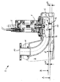
- the drawing shows a pump 1 of a sewage lifting system according to the invention 2, the bottom of a not shown Waste water container 3 is used.
- Pump 1 is a centrifugal pump an impeller 4 formed around the vertically arranged impeller axis 5 rotates.
- the pump 1 is arranged such that the suction opening 7 of the pump housing 8 coaxial to the impeller axis 5 is located above the bottom 9 of the waste water container 3.
- the pressure port 10 the pump 1 is at the upper end of an upward bent Pressure port 11.
- a short blank 12 from a is in the suction opening 7 flexible elastomer material is used, which extends coaxially vertically downwards extends in the direction of the bottom 9.
- the pipe section 12 has at its upper first end 13 has a collar 14 with an annular groove open to the outside, in which lie in the edge areas of the suction opening 7 of the pump housing 8. In this way, the pipe section 12 is positive and non-positive on the Pump housing 8 attached.
- the waste water is in this way through the lower free end 15 of the Pipe piece 12 sucked through, the pipe opening at the bottom free End 15 of the pipe section 12 by the amount ⁇ H with respect to the suction opening 7 of the pump housing 8 is shifted downwards.
- the respective safety distances S also result in the amount ⁇ H, um the achievable new switch-off level A below that previously the lowest possible switch-off level B.
Landscapes
- Health & Medical Sciences (AREA)
- Life Sciences & Earth Sciences (AREA)
- Engineering & Computer Science (AREA)
- Hydrology & Water Resources (AREA)
- Public Health (AREA)
- Water Supply & Treatment (AREA)
- Structures Of Non-Positive Displacement Pumps (AREA)
Abstract
Description
- 1
- Pumpe
- 2
- Abwasser-Hebeanlage
- 3
- Abwasserbehälters
- 4
- Laufrad
- 5
- Laufradachse
- 6
- Halteeinrichtung
- 7
- Saugöffnung
- 8
- Pumpengehäuse
- 9
- Boden
- 10
- Drucköffnung
- 11
- Druckstutzen
- 12
- Rohstück
- 13
- oberes erstes Ende
- 14
- Kragen
- 15
- unteres freies Ende
- ΔH
- Betrag
- S
- Sicherheitsabstand
- A
- neues Ausschaltniveau
- B
- altes Ausschaltniveau
Claims (8)
- Abwasser-Hebeanlage, umfassend eine Förderpumpe mit einer Saugöffnung und einer Drucköffnung, wobei die Pumpe derart von einer Halteeinrichtung gehalten ist, daß sich die Saugöffnung in einem Abstand über dem Boden eines Abwasserbehälters der Abwasser-Hebeanlage befindet, und wobei die Pumpe durch eine Niveau-Regeleinrichtung derart regelbar ist, daß sie bei Erreichen einer ersten vorgebbaren Niveauhöhe des Abwassers einschaltet und entweder bei Erreichen einer zweiten vorgebbaren Niveauhöhe des Abwassers oder nach Ablauf einer vorgebbaren Zeit ausschaltet,
dadurch gekennzeichnet, daß an der Saugöffnung (7) ein Rohrstück (12) vorgesehen ist, dessen erstes Ende (13) abgedichtet in die Saugöffnung (7) der Pumpe (1) mündet und dessen zweites bzw. freies Ende (15) sich näher an dem Boden (9) des Abwasserbehälters (3) befindet als die Saugöffnung (7), und daß das Rohrstück (12) flexibel biegbar ist. - Abwasser-Hebeanlage nach Anspruch 1, dadurch gekennzeichnet, daß das Rohrstück (12) aus einem Elastomer-Material besteht.
- Abwasser-Hebeanlage nach Anspruch 1 oder 2, dadurch gekennzeichnet, daß das Rohrstück (12) durch ein Schlauchstück gebildet ist.
- Abwasser-Hebeanlage nach einem der vorherigen Ansprüche, dadurch gekennzeichnet , daß das Rohrstück (12) formschlüssig und/oder kraftschlüssig in die Saugöffnung (7) der Pumpe (1) eingefügt ist.
- Abwasser-Hebeanlage nach einem der vorherigen Ansprüche, dadurch gekennzeichnet , daß das Rohrstück (12) stoffschlüssig an den die Saugöffnung (7) umgebenden Randbereichen der Pumpe (1) befestigt ist.
- Abwasser-Hebeanlage nach einem der vorherigen Ansprüche, dadurch gekennzeichnet, daß sich das Rohrstück (12) von der Saugöffnung (7) der Pumpe (1) aus senkrecht nach unten erstreckt.
- Abwasser-Hebeanlage nach einem der vorherigen Ansprüche, dadurch gekennzeichnet, daß der Durchmesser des Rohrstücks (12) größer ist als seine Länge.
- Abwasser-Hebeanlage nach einem der vorherigen Ansprüche, dadurch gekennzeichnet, daß die Halteeinrichtung (6) einstückig mit dem Pumpengehäuse (8) ausgebildet ist.
Applications Claiming Priority (2)
| Application Number | Priority Date | Filing Date | Title |
|---|---|---|---|
| DE2001132084 DE10132084A1 (de) | 2001-07-05 | 2001-07-05 | Abwasser-Hebeanlage mit tiefer Absaugung |
| DE10132084 | 2001-07-05 |
Publications (3)
| Publication Number | Publication Date |
|---|---|
| EP1273728A2 true EP1273728A2 (de) | 2003-01-08 |
| EP1273728A3 EP1273728A3 (de) | 2004-09-15 |
| EP1273728B1 EP1273728B1 (de) | 2006-03-01 |
Family
ID=7690371
Family Applications (1)
| Application Number | Title | Priority Date | Filing Date |
|---|---|---|---|
| EP20020012586 Expired - Lifetime EP1273728B1 (de) | 2001-07-05 | 2002-06-06 | Abwasser-Hebeanlage mit tiefer Absaugung |
Country Status (2)
| Country | Link |
|---|---|
| EP (1) | EP1273728B1 (de) |
| DE (2) | DE10132084A1 (de) |
Cited By (3)
| Publication number | Priority date | Publication date | Assignee | Title |
|---|---|---|---|---|
| EP3130712A1 (de) * | 2015-08-12 | 2017-02-15 | Wilo Se | Abwasserhebeanlage |
| EP3130711A1 (de) * | 2015-08-12 | 2017-02-15 | Wilo Se | Abwassersammelbehälter für eine abwasserhebeanlage und abwasserhebeanlage |
| EP3130710A1 (de) * | 2015-08-12 | 2017-02-15 | Wilo Se | Abwassersammelbehälter für eine abwasserhebeanlage und abwasserhebeanlage |
Families Citing this family (4)
| Publication number | Priority date | Publication date | Assignee | Title |
|---|---|---|---|---|
| DE102007008692A1 (de) | 2007-02-20 | 2008-08-21 | Ksb Aktiengesellschaft | Niveauabhängige Steuerung von Pumpen |
| DE102010060160B4 (de) | 2010-10-26 | 2016-03-24 | Aco Severin Ahlmann Gmbh & Co. Kg | Oberflächen-Entwässerungsrinne |
| DE102016225921A1 (de) | 2016-12-21 | 2018-06-21 | KSB SE & Co. KGaA | Abwasserhebeanlage mit Schneidwerk |
| LU500240B1 (de) | 2021-06-02 | 2022-12-02 | Wilo Se | Abwasserkreiselpumpe zur Tiefabsaugung gesammelten Abwassers |
Family Cites Families (6)
| Publication number | Priority date | Publication date | Assignee | Title |
|---|---|---|---|---|
| DE590848C (de) * | 1932-05-28 | 1934-01-12 | Hermann Fischer | Fluessigkeits-Foerdervorrichtung |
| DE1922484U (de) * | 1965-06-23 | 1965-08-26 | Herborner Pumpenfabrik J H Hof | Tauchpumpenaufhaengungsvorrichtung in faekalienbehaeltern. |
| DE1609166B1 (de) * | 1966-07-19 | 1970-07-09 | Wilfried Strate | Abwasserhebewerk |
| DE2404685A1 (de) * | 1974-02-01 | 1975-08-14 | Abs Pumps Ltd | Aborteinrichtung |
| FI57667C (fi) * | 1974-10-10 | 1980-09-10 | Waertsilae Oy Ab | Automatisk styranordning |
| DE7906936U1 (de) * | 1979-03-13 | 1979-06-07 | Jung-Pumpen Jung & Co, 4803 Steinhagen | Abwasserhebeanlage |
-
2001
- 2001-07-05 DE DE2001132084 patent/DE10132084A1/de not_active Withdrawn
-
2002
- 2002-06-06 DE DE50205904T patent/DE50205904D1/de not_active Expired - Lifetime
- 2002-06-06 EP EP20020012586 patent/EP1273728B1/de not_active Expired - Lifetime
Cited By (3)
| Publication number | Priority date | Publication date | Assignee | Title |
|---|---|---|---|---|
| EP3130712A1 (de) * | 2015-08-12 | 2017-02-15 | Wilo Se | Abwasserhebeanlage |
| EP3130711A1 (de) * | 2015-08-12 | 2017-02-15 | Wilo Se | Abwassersammelbehälter für eine abwasserhebeanlage und abwasserhebeanlage |
| EP3130710A1 (de) * | 2015-08-12 | 2017-02-15 | Wilo Se | Abwassersammelbehälter für eine abwasserhebeanlage und abwasserhebeanlage |
Also Published As
| Publication number | Publication date |
|---|---|
| EP1273728B1 (de) | 2006-03-01 |
| EP1273728A3 (de) | 2004-09-15 |
| DE50205904D1 (de) | 2006-05-04 |
| DE10132084A1 (de) | 2003-01-16 |
Similar Documents
| Publication | Publication Date | Title |
|---|---|---|
| DE69017729T2 (de) | Selbstbelüftetes Entleerungsventil. | |
| EP2045403B1 (de) | Ablaufgarnitur mit integriertem Überlauf | |
| DE2201317A1 (de) | Waermespeichernder boiler | |
| DE69612535T2 (de) | Vorgesteuertes Fluidumventil | |
| EP1273728B1 (de) | Abwasser-Hebeanlage mit tiefer Absaugung | |
| DE19923357A1 (de) | Flüssigkeitspumpenanordnung, insbesondere für die Verwendung in Haus und/oder Garten | |
| EP1329562A2 (de) | Ablaufvorrichtung für einen Boden | |
| EP0061041B1 (de) | Vorrichtung zum Betätigen eines heb- und senkbaren Ventilkegels eines Wannenablaufventils | |
| EP3455421B1 (de) | Ablaufventil für einen spülkasten und spülkasten mit ablaufventil | |
| CH716848B1 (de) | Becken mit Bodenablauf. | |
| EP0185109B1 (de) | Geruchsverschluss | |
| EP1548193A2 (de) | Vorrichtung zum Verhindern des Wassereintritts in einen Abwasserschacht | |
| EP0620329B1 (de) | Abflussregulator insbesondere für ein Regenwasser aufnehmendes Rückhaltebecken | |
| EP0153951A1 (de) | Schwimmerschalter, insbesondere für tauchpumpenaggregate | |
| DE3131010C2 (de) | Lenzvorrichtung für ölhaltiges Abwasser an Bord von Schiffen | |
| EP2072823B1 (de) | Kreiselpumpe mit Entlüftung | |
| DE2903277A1 (de) | Schraubenpumpe, insbesondere zur foerderung von abwasser u.dgl. | |
| EP4105398A1 (de) | Ablauftopf | |
| EP4001655B1 (de) | Tauchdruckpumpe für flüssigkeit und deren verwendung | |
| DE60121660T2 (de) | Taktweise bearbeitendes Spülventil | |
| DE102006015428B4 (de) | Be- und Entlüftungseinrichtung | |
| EP4344768B1 (de) | Mischvorrichtung zum mischen von chemikalien mit trinkwasser, system zum mischen von chemikalien mit trinkwasser sowie verwendung einer mischvorrichtung | |
| DE3716153A1 (de) | Behaelter fuer eine abwasser-pumpstation | |
| EP4375431A1 (de) | Becken mit ablauf | |
| DE202024105632U1 (de) | Klarwasser-Abzugseinrichtung, insbesondere für Kläranlagen und Speicherbecken |
Legal Events
| Date | Code | Title | Description |
|---|---|---|---|
| PUAI | Public reference made under article 153(3) epc to a published international application that has entered the european phase |
Free format text: ORIGINAL CODE: 0009012 |
|
| AK | Designated contracting states |
Kind code of ref document: A2 Designated state(s): AT BE CH CY DE DK ES FI FR GB GR IE IT LI LU MC NL PT SE TR |
|
| AX | Request for extension of the european patent |
Free format text: AL;LT;LV;MK;RO;SI |
|
| PUAL | Search report despatched |
Free format text: ORIGINAL CODE: 0009013 |
|
| AK | Designated contracting states |
Kind code of ref document: A3 Designated state(s): AT BE CH CY DE DK ES FI FR GB GR IE IT LI LU MC NL PT SE TR |
|
| AX | Request for extension of the european patent |
Extension state: AL LT LV MK RO SI |
|
| 17P | Request for examination filed |
Effective date: 20040901 |
|
| 17Q | First examination report despatched |
Effective date: 20041018 |
|
| AKX | Designation fees paid |
Designated state(s): DE FR GB IT |
|
| GRAP | Despatch of communication of intention to grant a patent |
Free format text: ORIGINAL CODE: EPIDOSNIGR1 |
|
| GRAS | Grant fee paid |
Free format text: ORIGINAL CODE: EPIDOSNIGR3 |
|
| GRAA | (expected) grant |
Free format text: ORIGINAL CODE: 0009210 |
|
| AK | Designated contracting states |
Kind code of ref document: B1 Designated state(s): DE FR GB IT |
|
| REG | Reference to a national code |
Ref country code: GB Ref legal event code: FG4D Free format text: NOT ENGLISH |
|
| REF | Corresponds to: |
Ref document number: 50205904 Country of ref document: DE Date of ref document: 20060504 Kind code of ref document: P |
|
| GBT | Gb: translation of ep patent filed (gb section 77(6)(a)/1977) |
Effective date: 20060515 |
|
| ET | Fr: translation filed | ||
| PLBE | No opposition filed within time limit |
Free format text: ORIGINAL CODE: 0009261 |
|
| STAA | Information on the status of an ep patent application or granted ep patent |
Free format text: STATUS: NO OPPOSITION FILED WITHIN TIME LIMIT |
|
| 26N | No opposition filed |
Effective date: 20061204 |
|
| PGFP | Annual fee paid to national office [announced via postgrant information from national office to epo] |
Ref country code: GB Payment date: 20140604 Year of fee payment: 13 |
|
| PGFP | Annual fee paid to national office [announced via postgrant information from national office to epo] |
Ref country code: IT Payment date: 20140612 Year of fee payment: 13 |
|
| PG25 | Lapsed in a contracting state [announced via postgrant information from national office to epo] |
Ref country code: IT Free format text: LAPSE BECAUSE OF NON-PAYMENT OF DUE FEES Effective date: 20150606 |
|
| GBPC | Gb: european patent ceased through non-payment of renewal fee |
Effective date: 20150606 |
|
| PG25 | Lapsed in a contracting state [announced via postgrant information from national office to epo] |
Ref country code: GB Free format text: LAPSE BECAUSE OF NON-PAYMENT OF DUE FEES Effective date: 20150606 |
|
| REG | Reference to a national code |
Ref country code: FR Ref legal event code: PLFP Year of fee payment: 15 |
|
| REG | Reference to a national code |
Ref country code: FR Ref legal event code: PLFP Year of fee payment: 16 |
|
| REG | Reference to a national code |
Ref country code: FR Ref legal event code: PLFP Year of fee payment: 17 |
|
| PGFP | Annual fee paid to national office [announced via postgrant information from national office to epo] |
Ref country code: DE Payment date: 20210519 Year of fee payment: 20 Ref country code: FR Payment date: 20210519 Year of fee payment: 20 |
|
| REG | Reference to a national code |
Ref country code: DE Ref legal event code: R071 Ref document number: 50205904 Country of ref document: DE |