EP1270367A2 - Appareil d'assistance au parking - Google Patents
Appareil d'assistance au parking Download PDFInfo
- Publication number
- EP1270367A2 EP1270367A2 EP02013707A EP02013707A EP1270367A2 EP 1270367 A2 EP1270367 A2 EP 1270367A2 EP 02013707 A EP02013707 A EP 02013707A EP 02013707 A EP02013707 A EP 02013707A EP 1270367 A2 EP1270367 A2 EP 1270367A2
- Authority
- EP
- European Patent Office
- Prior art keywords
- vehicle
- distance
- initial stop
- stop position
- parking
- Prior art date
- Legal status (The legal status is an assumption and is not a legal conclusion. Google has not performed a legal analysis and makes no representation as to the accuracy of the status listed.)
- Withdrawn
Links
Images


Classifications
-
- G—PHYSICS
- G08—SIGNALLING
- G08G—TRAFFIC CONTROL SYSTEMS
- G08G1/00—Traffic control systems for road vehicles
-
- B—PERFORMING OPERATIONS; TRANSPORTING
- B60—VEHICLES IN GENERAL
- B60T—VEHICLE BRAKE CONTROL SYSTEMS OR PARTS THEREOF; BRAKE CONTROL SYSTEMS OR PARTS THEREOF, IN GENERAL; ARRANGEMENT OF BRAKING ELEMENTS ON VEHICLES IN GENERAL; PORTABLE DEVICES FOR PREVENTING UNWANTED MOVEMENT OF VEHICLES; VEHICLE MODIFICATIONS TO FACILITATE COOLING OF BRAKES
- B60T8/00—Arrangements for adjusting wheel-braking force to meet varying vehicular or ground-surface conditions, e.g. limiting or varying distribution of braking force
- B60T8/17—Using electrical or electronic regulation means to control braking
- B60T8/172—Determining control parameters used in the regulation, e.g. by calculations involving measured or detected parameters
-
- B—PERFORMING OPERATIONS; TRANSPORTING
- B62—LAND VEHICLES FOR TRAVELLING OTHERWISE THAN ON RAILS
- B62D—MOTOR VEHICLES; TRAILERS
- B62D15/00—Steering not otherwise provided for
- B62D15/02—Steering position indicators ; Steering position determination; Steering aids
- B62D15/027—Parking aids, e.g. instruction means
- B62D15/028—Guided parking by providing commands to the driver, e.g. acoustically or optically
-
- B—PERFORMING OPERATIONS; TRANSPORTING
- B60—VEHICLES IN GENERAL
- B60T—VEHICLE BRAKE CONTROL SYSTEMS OR PARTS THEREOF; BRAKE CONTROL SYSTEMS OR PARTS THEREOF, IN GENERAL; ARRANGEMENT OF BRAKING ELEMENTS ON VEHICLES IN GENERAL; PORTABLE DEVICES FOR PREVENTING UNWANTED MOVEMENT OF VEHICLES; VEHICLE MODIFICATIONS TO FACILITATE COOLING OF BRAKES
- B60T2201/00—Particular use of vehicle brake systems; Special systems using also the brakes; Special software modules within the brake system controller
- B60T2201/10—Automatic or semi-automatic parking aid systems
Definitions
- the present invention relates to a parking assisting device, and more particularly to a device for guiding a driver a driving operation upon parking.
- an assisting device for showing a rear view of a vehicle on a television screen in a state where the vehicle stops in an initial stop position at a time of parking and superimposing to display on the television screen guiding information on a driving operation that is necessary for the parking.
- parking can be easily conducted by merely performing the driving operation following the guiding information displayed on the television screen.
- the present invention is made in view of solving the above-mentioned problem, and it is an object of the present invention to provide a parking assisting device capable of accurately guiding a driving operation even when a vehicle is not precisely stopped in a previously set reference position for an initial stop and performing parking assistance with high accuracy.
- Aparking assisting device includes: a first distance sensor for measuring a distance to an obstacle on a side of a vehicle; a second distance sensor for measuring a moving distance of the vehicle; yaw angle detecting means for detecting a yaw angle of the vehicle; guiding means for outputting guiding information on a driving operation to a driver; and a controller for grasping an initial stop position based on the distance to the obstacle on the side of the vehicle measured by the first distance sensor and the moving distance of the vehicle measured by the second distance sensor at a time of an advancing operation of the vehicle until reaching the initial stop position and for providing to the driver via the guiding means appropriate timing for a temporal stop for back parking based on the initial stop position and the yaw angle detected by the yaw angle detecting means.
- the controller so as to measure a deviation between an actual initial stop position and a reference position for the initial stop based on the distance to the obstacle on the side of the vehicle measured by the first distance sensor and the moving distance of the vehicle measured by the second distance sensor and simultaneously to calculate the appropriate timing for the temporal stop for the back parking based on the measured deviation and the yaw angle detected by the yaw angle detecting means.
- the controller may guide via the guiding means the driver to an effect of stopping the vehicle when the controller judges that the vehicle has reached the initial stop position based on the distance to the obstacle on the side of the vehicle measured by the first distance sensor and the moving distance of the vehicle measured by the second distance sensor at the time of the advancing operation of the vehicle until reaching the initial stop position.
- the controller can provide via the guiding means to the driver the guiding information of: advancing the vehicle with a steering angle at the maximum from the initial stop position and stopping the vehicle in a back start position; moving the vehicle backward with the steering angle at the maximum in an opposite direction from the back start position and stopping the vehicle in a steering wheel cutting position; and moving the vehicle backward with the steering angle at the maximum in the opposite direction again from the steering wheel cutting position so as to cause the vehicle to reach a target parking space.
- controller so as to calculate the appropriate timing for the temporal stop through calculating an inclination of the vehicle with respect to the target parking space based on the distance to the obstacle on the side of the vehicle measured by the first distance sensor and the moving distance of the vehicle measured by the second distance sensor at the time of the advancing operation of the vehicle until reaching the initial stop position and adding this inclination to the deviation between the actual initial stop position and the reference position for the initial stop.
- controller so as to calculate a suitable initial stop position based on the distance to the obstacle on the side of the vehicle measured by the first distance sensor and simultaneously guide via the guiding means the driver to an effect of stopping the vehicle when the controller judges that the vehicle has reached the initial stop position based on the moving distance of the vehicle measured by the second distance sensor.
- the controller can provide via the guiding means to the driver guiding information of: moving the vehicle backward with the steering angle at the maximum from the initial stop position and stopping the vehicle at the steering wheel cutting position; and moving the vehicle backward with the steering angle at the maximum in the opposite direction from the steering wheel cutting position so as to cause the vehicle to reach the target parking space.
- the controller may calculate the inclination of the vehicle with respect to the target parking space based on the distance to the obstacle on the side of the vehicle measured by the first distance sensor and the moving distance of the vehicle measured by the second distance sensor at the time of the advancing operation of the vehicle until reaching the initial stop position, and calculate the suitable initial stop position according to this inclination.
- the controller can also store as a history the distance to the obstacle on the side of the vehicle measured by the first distance sensor and the moving distance of the vehicle measured by the second distance sensor and simultaneously calculate the suitable initial stop position based on this history.
- the controller can also measure a length of the target parking space based on the distance to the obstacle on the side of the vehicle measured by the first distance sensor and the moving distance of the vehicle measured by the second distance sensor at the time of the advancing operation of the vehicle until reaching the initial stop position.
- the controller may give a warning to the driver in a case where interference of the vehicle with the obstacle is predicted when the vehicle moves under a state of being held at a uniform steering angle.
- Fig. 1 shows a construction of a parking assisting device in accordance with Embodiment 1 of the present invention.
- a controller 1 Connected to a controller 1 are: a yaw rate sensor 2 for detecting an angular speed in a direction of a yaw angle of a vehicle; a switch module 5 constituted by an in-parallel mode switch 3 for informing the controller 1 that a vehicle is parked in parallel; and an in-line mode switch 4 for informing the controller 1 that the vehicle is parked in line.
- a speaker 6 for guiding driver information on a driving operation is connected with the controller 1.
- the controller 1 is connected with an ultrasonic sensor 7 serving as a first distance sensor for measuring a distance to an obstacle on a side of the vehicle and a wheel speed sensor 8 serving as a second distance sensor for measuring a moving distance of the vehicle.
- the wheel speed sensor 8 detects rpm of wheels of the vehicle, and can calculate the moving distance of the vehicle based on a signal from the wheel speed sensor 8 by means of the controller 1.
- the switch module 5 and the speaker 6 are arranged in a driver seat, and the ultrasonic sensor 7 is installed on a front end side portion of the vehicle.
- the controller 1 is provided with a CPU, a ROM storing a control program and a working RAM (not shown).
- the ROM there is stored data on a minimum turning radius Rc for a case where the vehicle turns with a steering wheel of the vehicle steered at maximum.
- the control program for performing parking assistance upon the in-parallel parking and the in-line parking of the vehicle is stored in the ROM.
- the CPU operates based on the control program stored in the ROM.
- the controller 1 calculates a yaw angle of the vehicle from the angular speed of the vehicle inputted from the yaw rate sensor 2, calculates a turning angle of the vehicle and outputs information on an operation method and operation timing in each step during the parking operation to the speaker 6.
- a vehicle 10 is parked in a parking frame T such that a rear left end of the vehicle 10 coincides with a corner S2 in the back of the parking frame T.
- a rear axle center MO of the vehicle 10 in a vehicle position M1 in this state is assumed to be an origin, and a Y axis is taken in a direction in parallel with a road, which is a backward direction of the vehicle 10, and an X axis is taken perpendicularly to the Y axis.
- coordinates at the corner in the back of the parking frame T are assumed to be S2(W2/2, a2).
- a2 and W2 denote a rear overhang and a vehicle width of the vehicle 10, respectively.
- the vehicle 10 in a vehicle position J1 advances while turning at the radius Rc with a steering angle of the steering wheel at the maximum rightward; when the vehicle 10 reaches a vehicle position K1, the vehicle 10 moves backward while turning at the radius Rc with the steering angle at the maximum leftward; and, when the vehicle reaches a vehicle position L1, the vehicle 10 moves backward while turning at the radius Rc with the steering angle at the maximum right ward to appropriately be parked in the vehicle position M1 within the parking frame T.
- the in-line parking is started with a vehicle 20 parked in a predetermined position in front of the parking frame T as a mark and that a state in which the vehicle 10 is parked in the vehicle position J1 is an initial stop position.
- the vehicle position J1 is assumed to be a position where a Y coordinate of a position DR of a driver of the vehicle 10 coincides with the Y coordinate of a rear end 20a of the parked vehicle 20, which is a position in parallel with the parking frame T and a position where the vehicle 10 and the vehicle 20 are spaced apart from each other by a predetermined vehicle distance d. Therefore, coordinates (JOx, JOy) of a rear axle center JO of the vehicle position J1 are unconditionally defined from the relationship between the coordinates of the rear end 20a of the vehicle 20, the position DR of the driver and the rear axle center JO, and the vehicle distance d.
- the vehicle 10 in the vehicle position J1 advances to the vehicle position K1 while turning at the radius Rc with the steering angle of the steering wheel at the maximum rightward.
- a turning center is assumed to be C3 and a turning angle is assumed to be ⁇ .
- the vehicle 10 in the vehicle position K1 moves backward to the vehicle position L1 while turning at the radius Rc with the steering angle at the maximum leftward.
- a turning center is assumed to be C4 and a turning angle is assumed to be ⁇ .
- the steering wheel is cut in the opposite direction in the vehicle position L1 and the vehicle 1 moves backward to the vehicle position M1 while turning at the minimum turning radius Rc with the steering angle at the maximum rightward.
- a turning center is assumed to be C5 and a turning angle is assumed to be ⁇ .
- rear axle centers in the vehicle positions K1 and L1 are assumed to be KO and LO, respectively.
- Coordinates (C4x, C4y) of the turning center C4 are represented by the following expressions.
- Coordinates (C3x, C3y) of the turning center C3 are represented by the following expressions.
- coordinates (JOx, JOy) of the rear axle center JO of the vehicle position J1 are represented by the following expressions.
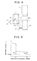
- the vehicle 10 advances straight forward in parallel with the road, namely, in parallel with the target parking frame T, to the vehicle position J1, which is the position where the Y coordinate of the position DR of the driver coincides with the Y coordinate of the rear end 20a of the parked vehicle 20 and the vehicle 10 and the vehicle 20 are spaced apart from each other by the vehicle distance d, for example, by 50 cm.
- the vehicle 10 advances, measurement of a distance from the vehicle 10 to the obstacle on the side of the vehicle, the parked vehicle 20, for example, is continuously performed by means of the ultrasonic sensor 7 that is installed on the front end side portion of the vehicle.
- the vehicle 10 gradually approaches the vehicle position J1, and reaches the position where the Y coordinate of the position DR of the driver coincides with the Y coordinate of the rear end 20a of the parked vehicle 20, as shown in Fig. 4.
- Fig. 5 shows a measured distance x to the obstacle corresponding to the position of the ultrasonic sensor 7, being accompanied with the vehicle 10 that is advancing.
- the measured distance x becomes an extremely large value when the vehicle 10 passes the side of the parking frame T.
- a Y coordinate of the ultrasonic sensor 7 reaches a coordinate y1, which coincides with the Y coordinate of the rear end 20a of the parked vehicle 20, the measured distance x abruptly decreases to be a distance from the ultrasonic sensor 7 to the vehicle 20.
- the measured distance x in this case can be expressed by a sum of the distance of 50 cm from the vehicle 20, which is a reference position ST for the initial stop, and a deviation dx1 in an x direction.
- the controller 1 can recognize that the ultrasonic sensor 7 has arrived at the coordinate y1 based on this abrupt change in the measured distance x. Then, the controller 1 stores a length LD from a front end of the vehicle 10 to the position DR of the driver in advance and monitors a moving distance of the vehicle 10, which was calculated by a signal from the wheel speed sensor 8. When the vehicle 10 has advanced by the distance LD from the point where the ultrasonic sensor 7 reaches the coordinate y1, specific stop sound is emitted for the driver via the speaker 6. The driver stops the vehicle 10 upon hearing this stop sound. As a result, the Y coordinate of the position DR of the driver coincides with the Y coordinate of the rear end 20a of the parked vehicle 20, whereby the position is made to be the initial stop position.
- the measured distance x obtained by the ultrasonic sensor 7 in this case can be expressed by a sum of the distance of 50 cm from the vehicle 20 serving as the reference position ST for the initial stop and a deviation dx2 in the x direction.
- the deviation dx1 and the deviation dx2 are equal to each other when the vehicle 10 travels in parallel with the parked vehicle 20.
- the distance between the coordinates y1 and y2 is the distance LD that is stored in advance in the controller 1.
- the controller 1 obtains coordinates (JOx+dx, JOy+dy) of a rear axle center JO' as an actual initial stop position from the thus measured deviations dx1 and dx2 and the normal coordinates JOx and JOy of the rear axle center JO, to thereby calculate the above-mentioned turning angles a, ⁇ and ⁇ so as to appropriately park the vehicle 10 in line in the parking frame T.
- the controller 1 sets the initial stop position as a position where the yaw angle of the vehicle is zero degree and simultaneously activates a program for in-line parking based on the operation of the in-line mode switch 4.
- the driver steers the steering wheel of the vehicle 10 to the maximum rightward to bring it to a fully cut state and advances the vehicle 10 in that state.
- the controller 1 calculates the yaw angle of the vehicle from the angular speed of the vehicle 10 inputted from the yaw rate sensor 2 and compares this yaw angle with the value of the calculated turning angle ⁇ .
- the controller 1 informs the driver of approach information notifying that the vehicle has approached the vehicle position K1 and arrival information notifying that the vehicle has reached the vehicle position K1 based on the difference between the yaw angle and the calculated turning angle ⁇ via the speaker 6.
- intermittent sound such as "blip, blip” is emitted from the speaker 6 as the approach information, and the cycle of this intermittent sound and blinking becomes shorter when the difference between the yaw angle and the turning angle ⁇ is decreased.
- continuous sound such as "bleep” is emitted from the speaker 6 as the arrival information.
- the driver stops the vehicle 10 in the vehicle position K1 in accordance with the arrival information. Next, the driver steers the steering wheel to the maximum leftward to bring it to a fully cut state and moves the vehicle 10 backward in that state.
- the controller 1 informs the driver of approach information notifying that the vehicle has approached the vehicle position L1 and arrival information notifying that the vehicle has reached the vehicle position L1 based on the difference between the yaw angle and the calculated turning angle ⁇ via the speaker 6.
- the driver cuts the steering wheel in the opposite direction in the vehicle position L1, steers it to the maximum rightward to bring it to a fully cut state and moves the vehicle 10 backward in that state.
- the controller 1 informs the driver of approach information notifying that the vehicle has approached the vehicle position M1 within the parking frame T and arrival information notifying that the vehicle has reached the vehicle position M1 via the speaker 6. In this manner, the driver stops the vehicle 10 in the vehicle position M1, whereby the parking is completed.
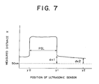
- a parking assisting device according to Embodiment 2 has the same construction as the parking assisting device of Embodiment 1 shown in Fig. 1. However, as shown in Fig. 6, the parking assisting device according to this embodiment is effective in a case where not only is the vehicle 20 already parked in front of the target parking frame T but also a vehicle 30 is parked behind the target parking frame T.
- a distance x measured with the ultrasonic sensor 7 is shown in Fig. 7.
- a distance to the vehicle 30 that is parked behind the parking frame T is measured first.
- a vehicle does not exist after a time when a Y coordinate of the ultrasonic sensor 7 reaches a coordinate y0 which coincides with a Y coordinate of a front end 30a of the parked vehicle 30, and thus the measured distance x becomes an extremely large value.
- the controller 1 can recognize that the ultrasonic sensor 7 has arrived at the coordinates y0 and y1 based on this abrupt change in the measured distance x, and a distance PSL by which the vehicle 10 has moved during the above-mentioned operation can be calculated using a signal from the wheel speed sensor 8.
- This distance PSL expresses a length of a parking space formed by the parked vehicles 30 and 20.
- the ultrasonic sensor 7 After the ultrasonic sensor 7 reaches the coordinate y1, as in Embodiment 1, when the vehicle 10 has advanced by the distance LD and the ultrasonic sensor 7 reaches the coordinate y2, specific stop sound is emitted for the driver via the speaker 6. The driver stops the vehicle 10 upon hearing this stop sound. As a result, the Y coordinate of the position DR of the driver becomes a position which coincides with the Y coordinate of the rear end 20a of the parked vehicle 20, which becomes the initial stop position.
- the controller 1 calculates the turning angles ⁇ , ⁇ and ⁇ so that the driver can appropriately park the vehicle 10 in line from the actual initial stop position to the parking frame T based on the measured deviations dx1 and dx2 and the length PSL of the parking space.
- the controller 1 provides the driver appropriate timing for a temporal stop under a fully cut state of the steering wheel via the speaker 6 based on the thus calculated turning angles ⁇ , ⁇ and ⁇ , whereby the driver can complete the in-line parking to the parking frame T.
- a parking assisting device has the same construction as the parking assisting device of Embodiment 1 shown in Fig. 1.
- the parking assisting device according to this embodiment is a device provided not for stopping the vehicle in the reference position for the initial stop set in advance, but for guiding the driver an appropriate initial stop position that is calculated by the controller 1 based on a distance x to an obstacle on a side of the vehicle measured by the ultrasonic sensor 7 .
- guiding information is provided to the driver, in which: the vehicle moves backward by bringing the steering angle to the maximum from the initial stop position and the vehicle stops in a steering wheel cutting position; and the vehicle moves backward by bringing the steering angle to the maximum in the opposite direction from the steering wheel cutting position, whereby the vehicle reaches the target parking space.
- a vehicle distance between the vehicle 10 and the parked vehicle 20 is assumed to be B.
- a distance DX by which the vehicle 10 should be moved in an X direction through a parking operation is represented by the following expression.
- DX B+W2
- a turning angle by which a rear axle center of the vehicle 10 moves from P0 in an initial stop position P1 to Q0 in a steering wheel cutting position Q1 is assumed to be ⁇ and a minimum turning radius of the rear axle center is assumed to be Rc, it is represented by the following expression.
- DX 2Rc ⁇ (1-cos ⁇ )
- the distance DX can be measured by the ultrasonic sensor 7 and the minimum turning radius Rc is known, and thus the turning angle ⁇ can be calculated from the above-mentioned expression.
- An interference allowance between a right rear end Z of the parked vehicle 20 and a left front end of the vehicle 10 upon turning of the vehicle 10 is assumed to be F. Note that, in Fig. 8, both interfere with each other, and thus F becomes a negative value.
- a turning radius Rf1 of the left front end of the vehicle 10 is represented by the following expression by assuming a full length of the vehicle 10 as L.
- Rf1 ⁇ (Rc+W2/2) 2 +(L-a2) 2 ⁇ 1/2
- a distance ZC7 between the right rear end Z of the vehicle 20 and a turning center C7 of the vehicle 10 is represented by the following expression using a distance E between the right rear end Z of the vehicle 20 and the turning center C7 of the vehicle 10 in the Y direction.
- ZC7 ⁇ (Rc-W2/2) 2 +E 2 ⁇ 1/2
- the interference allowance F is represented by the following expression.
- F ZC7-Rf1 Therefore, the value of the distance E can be determined by substituting a specific numerical value, for example, 40 cm, for F.
- a forward distance D from a rear end of the parked vehicle 20 to a front end of the vehicle 10 at the initial stop position P1 is represented by the following expression.
- D DY-E+L-a2
- the vehicle 10 advances forward in parallel with a road, and the in-line mode switch 4 is actuated while the vehicle 10 passes the side of the parking space.
- measurement of a distance to the parked vehicle 20 is continuously performed by means of the ultrasonic sensor 7 installed on the front end side portion of the vehicle 10.
- the controller 1 recognizes that the ultrasonic sensor 7 reaches the rear end position of the vehicle 20 and simultaneously measures the vehicle distance B between the vehicle 10 and the vehicle 20. According to the above-mentioned procedure, the forward distance D from the rear end of the vehicle 20 to the front end of the suitable initial stop position P1 and the turning angle ⁇ required thereafter can be determined.
- the controller 1 monitors a moving distance of the vehicle 10 calculated using a signal from the wheel speed sensor 8.
- a signal from the wheel speed sensor 8 When the vehicle 10 has advanced by the forward distance D from a point where the ultrasonic sensor 7 reaches the rear end position of the parked vehicle 20, specific stop sound is emitted for the driver via the speaker 6. The driver stops the vehicle 10 upon hearing this stop sound. As a result, the vehicle 10 stops in the suitable initial stop position P1. In this case, the controller 1 resets a yaw angle of the vehicle 10 obtained by the yaw rate sensor 2.
- the controller 1 compares the yaw angle of the vehicle to the value of the determined turning angle ⁇ , outputs approach information via the speaker 6 when the yaw angle approaches the turning angle ⁇ , and further outputs arrival information via the speaker 6 when the yaw angle becomes equal to the turning angle ⁇ , judging that the vehicle 10 has reached the steering wheel cutting position Q1.
- the driver stops the vehicle 10 in the steering wheel cutting position Q1 according to the arrival information.
- the driver cuts the steering wheel in the opposite direction and steers it to the maximum rightward to bring it to a fully cut state, and moves the vehicle 10 backward in that state.
- the controller 1 informs the driver of the approach information notifying that the vehicle has approached a vehicle position R1 within the target parking space and the arrival information notifying that the vehicle has reached the vehicle position R1 via the speaker 6. In this manner, the driver can stop the vehicle 10 in the vehicle position R1, whereby parking is completed.
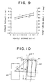
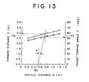
- the relationship of the distance D from the rear end of the parked vehicle 20 to the front end of the suitable initial stop position P1 and the vehicle distance B of the turning angle ⁇ required thereafter is determined based on characteristics of the vehicle 10 as shown in, for example, Fig. 9.
- Embodiment 3 in the same manner as in Embodiment 2, it is possible to guide capability and incapability of the parking through measuring the length of the target parking space when the vehicle advances straight forward toward the initial stop position, and to warn interference with the obstacle such as the vehicle that is parked behind.
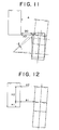
- Embodiment 4 is effective for a case where a direction in which the vehicle advances straight forward toward the initial stop position is not in parallel with the parked vehicle 20 but has an inclination angle ⁇ .
- the vehicle 10 in a position P2 that is parked in a state of being inclined by the angle ⁇ can be regarded to be in a state where the vehicle 10 moves backward by the angle ⁇ through a parking operation from a position P1 where the vehicle 10 stops in parallel with the parked vehicle 20.
- coordinates (X1f, Y1f) of a left front end of the vehicle 10 in the position P2 are represented by the following expressions by using coordinates (X0f, Y0f) of a left front end of the vehicle 10 in the position P1 by taking a turning center as an origin.
- X1f X0f ⁇ cos ⁇ +Y0f ⁇ sin ⁇
- ⁇ X1f (L-a2) ⁇ sin ⁇ -(Rc-W2/2) ⁇ (1-cos ⁇ )
- a horizontal distance B0 of the vehicle that is in parallel with the vehicle 20 corresponding to this distance A0 is represented by the following expression.
- the inclination angle ⁇ is obtained from: a vehicle distance A1 of the vehicle 10 to the vehicle 20 obtained when the vehicle 10 has advanced by a distance H1 from the point where the ultrasonic sensor 7 detects the rear end of the parked vehicle 20; and a vehicle distance A2 of the vehicle 10 to the vehicle 20 obtained when the vehicle 10 has further advanced by a distance H2, which is represented by the following expression.
- ⁇ tan -1 ⁇ (A2-A1)/H2 ⁇
- a suitable forward distance Da for a case where the vehicle 10 is replaced by the vehicle that is in parallel with the parked vehicle 20 based on an intersection point of a solid line of the inclination ⁇ extending from a point of the vehicle distance B0 when the forward distance D is 0 with a curve representing the forward distance D.
- a suitable turning angle ⁇ a can be obtained based on an intersection point of a solid line that is drawn in parallel with a Y axis from the intersection point of the solid line of the inclination ⁇ with the curve representing the forward distance D with the curve representing the turning angle ⁇ .
- a Y direction displacement ⁇ Y1f of the left front end of the vehicle 10 between the positions P1 and P2 can be represented by the following expression.
- ⁇ Y1f - ⁇ (Rc-W2/2) ⁇ sin ⁇ +(L-a2) ⁇ (1-cos ⁇ ) ⁇
- the vehicle inclined by the angle ⁇ positions being separated backward by the above-mentioned Y direction displacement ⁇ Y1f from the vehicle in parallel with the parked vehicle 20.
- the vehicle may move in a Y direction by a distance, which is obtained by subtracting the Y direction displacement ⁇ Y1f from the forward distance Da, and may move in an inclined direction of the angle ⁇ by a distance D1, which is represented by the following expression.
- the vehicle has already turned by the angle ⁇ from the vehicle in parallel with the parked vehicle 20.
- a turning angle to a target parking space from the steering wheel cutting position is ⁇ a.
- Embodiment 3 in a case where it is judged that the direction in which the vehicle advances straight forward toward the initial stop position inclines by the angles with respect to the parked vehicle 20, guiding information may be outputted to the driver so as to stop the vehicle 10 when the vehicle has advanced slantly by the above-mentioned distance D1 from the point where the ultrasonic sensor 7 reaches the rear end position of the parked vehicle 20; again stop the vehicle when the vehicle has moved backward by the angle ⁇ 1 from the initial stop position with the steering wheel steered at the maximum leftward; and complete the parking when the vehicle has moved backward by the angle ⁇ a with the steering wheel cut at the maximum rightward.
- Embodiment 4 in the same manner as in Embodiment 2, it is possible to guide capability and incapability of the parking through measuring the length of the target parking space when the vehicle advances straight forward toward the initial stop position, and to warn interference with the obstacle such as the vehicle that is parked behind.
- the initial stop position is calculated in Embodiment 5 by constantly performing a measurement of a distance to the obstacle on the side of the vehicle by means of the ultrasonic sensor 7 and a measurement of a traveling distance of the vehicle by means of the wheel speed sensor 8, storing the distance to the obstacle on the side of the vehicle according to the traveling distance as a history, and using this history for the calculation.
- the controller 1 constantly actuates the ultrasonic sensor 7 and the wheel speed sensor 8, and stores as a history the distance to the obstacle on the side of the vehicle according to the traveling distance for a past predetermined amount of time or predetermined traveling distance based on a signal inputted from these sensors.
- the vehicle 10 stops on the side of the parked vehicle 20 by passing the side of the parking space in the same manner as it does in the initial stop position of Embodiments 3 and 4, for example, and the in-line mode switch 4 is actuated.
- the controller 1 calculates an appropriate initial stop position for in-line parking in the parking space through the calculation method described in Embodiment 3 or 4, based on the history of the distance to the obstacle on the side of the vehicle according to the traveling distance for the predetermined amount of time or the predetermined traveling distance before the stop of the vehicle.
- the controller 1 guides the driver to cause the vehicle to reach the initial stop position by advancing the vehicle straight forward or moving the vehicle straight backward via the speaker 6.
- the controller 1 further guides the driver to advance the vehicle straight forward or to move the vehicle straight backward via the speaker 6 and adds to the stored history a relationship between the traveling distance and the distance to the obstacle obtained during the above-mentioned operation, to thereby calculate the initial stop position. Thereafter, the controller 1 guides the driver to cause the vehicle to reach the initial stop position by advancing the vehicle straight forward or moving the vehicle straight backward via the speaker 6.
- the controller 1 After the vehicle 10 stops in the initial stop position as described above, the controller 1 provides via the speaker 6 to the driver guiding information for causing the vehicle 10 to reach the steering wheel cutting position and further to reach the parking space, in the same manner as in Embodiment 3 or 4.
- Embodiment 5 in the same manner as in Embodiments 2 to 4, it is possible to guide capability and incapability of the parking through measuring the length of the target parking space when the vehicle advances straight forward toward the initial stop position, and to warn interference with the obstacle such as the vehicle that is parked behind.
- Embodiment 5 by only stopping the vehicle 10 in any position and actuating the in-line mode switch 4, the appropriate initial stop position is calculated based on the past history, whereby a parking assisting device that is excellent in operability can be realized.
- Fig. 14 shows a parking assisting device according to Embodiment 6.
- the parking assisting device according to Embodiment 6 is, in the device of Embodiment 1 shown in Fig. 1, installed on a front end side portion of the vehicle with an optical sensor 9 as the first distance sensor instead of the ultrasonic sensor 7 for measuring a distance to the obstacle on the side of the vehicle.
- Embodiment 6 in the same manner as in Embodiments 1 to 5, it is possible to provide the driver appropriate timing for the temporal stop under the fully cut state of the steering wheel via the speaker 6 and complete in-line parking in the parking frame T.
- the optical sensor 9 can be constituted by a combination of light emitting means such as an LED or a laser diode and light receiving means such as a phototransistor or a CCD device. Further, a sensor utilizing an electromagnetic wave other than light such as a radar may also be used instead of the optical sensor 9.
- Embodiments 1 to 6 described above it is possible to constitute the device so as to give a warning to the driver via the speaker 6 in a case where it is impossible to calculate the turning angle that is applicable to the parking operation due to a large deviation and in a case where interference of the vehicle 10 with the obstacle such as the parked vehicle 20 upon in-line parking is predicted when turning the vehicle 10 at the turning angle obtained based on the steering angle that is held at the maximum. In this manner, it is possible to prevent the vehicle 10 from interfering with the obstacle, according to the turning angle that is calculated by considering a positional deviation of the initial stop position.
- the yaw rate sensor is used as yaw angle detecting means.
- the means for detecting the yaw angle may also include a method using a position gyroscope or a method for detecting the yaw angle from a difference in rotation obtained by rotation sensors that are mounted to left and right wheels, respectively.
- a method using a terrestrial magnetism sensor or a GPS system may also be used.
- the approach information and the arrival information may change volume and timbre of the sound emitted from the speaker 6, or may cause sound having different contents to be emitted, for every vehicle position that is the target of the approach and the arrival of the vehicle.
- the guiding means is not limited to the speaker 6 and may be a buzzer, an LED or a lamp, and characters or marks may also be displayed on a display. Further, vibration may also be used, which is transmitted to the driver via the steering wheel or the like.
- the first distance sensor measures the distance to the obstacle on the side of the vehicle and simultaneously the second distance sensor measures the moving distance of the vehicle at the time of the advancing operation of the vehicle until reaching the initial stop position, and the controller grasps the initial stop position based on those measured distances and provides to the driver via the guiding means the appropriate timing for the temporal stop for the back parking based on the initial stop position and the yaw angle detected by the yaw angle detecting means.
- the controller grasps the initial stop position based on those measured distances and provides to the driver via the guiding means the appropriate timing for the temporal stop for the back parking based on the initial stop position and the yaw angle detected by the yaw angle detecting means.
- a vehicle advances in parallel with a parking frame to reach an initial stop position
- measurement of a distance to a parked vehicle is continuously performed by means of an ultrasonic sensor and a moving distance of the vehicle is simultaneously calculated using a signal from a wheel speed sensor.
- a turning angle is calculated so as to enable appropriate in-line parking to the parking frame from an actual initial stop position, based on a deviation of the vehicle from a reference position for the initial stop measured by the ultrasonic sensor.
- Information on a driving operation that is necessary for back parking is provided to a driver via a speaker based on this turning angle and output from a yaw rate sensor.
Landscapes
- Engineering & Computer Science (AREA)
- Transportation (AREA)
- Mechanical Engineering (AREA)
- Chemical & Material Sciences (AREA)
- Combustion & Propulsion (AREA)
- Physics & Mathematics (AREA)
- General Physics & Mathematics (AREA)
- Traffic Control Systems (AREA)
- Measurement Of Velocity Or Position Using Acoustic Or Ultrasonic Waves (AREA)
- Control Of Position, Course, Altitude, Or Attitude Of Moving Bodies (AREA)
- Steering Control In Accordance With Driving Conditions (AREA)
Applications Claiming Priority (4)
| Application Number | Priority Date | Filing Date | Title |
|---|---|---|---|
| JP2001199021 | 2001-06-29 | ||
| JP2001199021 | 2001-06-29 | ||
| JP2001399992A JP4161573B2 (ja) | 2001-06-29 | 2001-12-28 | 駐車支援装置 |
| JP2001399992 | 2001-12-28 |
Publications (2)
| Publication Number | Publication Date |
|---|---|
| EP1270367A2 true EP1270367A2 (fr) | 2003-01-02 |
| EP1270367A3 EP1270367A3 (fr) | 2006-05-10 |
Family
ID=26617887
Family Applications (1)
| Application Number | Title | Priority Date | Filing Date |
|---|---|---|---|
| EP02013707A Withdrawn EP1270367A3 (fr) | 2001-06-29 | 2002-06-20 | Appareil d'assistance au parking |
Country Status (5)
| Country | Link |
|---|---|
| US (1) | US6898527B2 (fr) |
| EP (1) | EP1270367A3 (fr) |
| JP (1) | JP4161573B2 (fr) |
| KR (1) | KR100476148B1 (fr) |
| CN (1) | CN1244468C (fr) |
Cited By (15)
| Publication number | Priority date | Publication date | Assignee | Title |
|---|---|---|---|---|
| EP1346901A3 (fr) * | 2002-03-22 | 2004-04-21 | Toyota Jidosha Kabushiki Kaisha | Système et procédé de contrôle automatique de direction |
| EP1553009A2 (fr) * | 2004-01-07 | 2005-07-13 | Robert Bosch GmbH | Assistance pour se garer en créneau |
| FR2872122A1 (fr) * | 2004-06-23 | 2005-12-30 | Denso Corp | Systeme d'assistance au stationnement |
| EP1674376A2 (fr) * | 2004-12-21 | 2006-06-28 | Aisin Seiki Kabushiki Kaisha | Dispositf d'assistance au parking |
| EP1908656A1 (fr) * | 2005-07-28 | 2008-04-09 | Advics Co., Ltd. | Contrôleur d assistance au stationnement et système contrôle d assistance au stationnement |
| EP2003021A2 (fr) * | 2006-03-31 | 2008-12-17 | Aisin Seiki Kabushiki Kaisha | Dispositif d'aide au stationnement |
| EP2011701A1 (fr) * | 2006-04-25 | 2009-01-07 | Toyota Jidosha Kabushiki Kaisha | Dispositif et procede d'aide au stationnement |
| US7486203B2 (en) | 2004-04-27 | 2009-02-03 | Aisin Seiki Kabushiki Kaisha | Parking assist apparatus for vehicle |
| DE102007036251A1 (de) | 2007-08-02 | 2009-02-05 | Robert Bosch Gmbh | Verfahren und Vorrichtung zum Unterstützen von Ausparkvorgängen von Kraftfahrzeugen |
| WO2011020784A1 (fr) * | 2009-08-20 | 2011-02-24 | Robert Bosch Gmbh | Procédé pour vérifier l'environnement d'un véhicule à moteur |
| WO2011038978A1 (fr) | 2009-10-02 | 2011-04-07 | Robert Bosch Gmbh | Procédé pour représenter l'environnement d'un véhicule |
| DE102010028830A1 (de) | 2010-05-11 | 2011-11-17 | Robert Bosch Gmbh | Fahrerassistenzsystem mit Ansteuerung des Fahrzeugbremssystems und Abstandswarnung |
| US8130120B2 (en) | 2007-02-27 | 2012-03-06 | Toyota Jidosha Kabushiki Kaisha | Parking assistance device |
| EP2993111A1 (fr) * | 2014-07-31 | 2016-03-09 | Valeo Schalter und Sensoren GmbH | Procédé d'assistance d'un conducteur lors du stationnement d'un véhicule automobile, système d'assistance de conducteur et véhicule automobile |
| DE102014209213B4 (de) * | 2013-11-21 | 2020-09-03 | Hyundai Mobis Co., Ltd. | Parkassistenzsystem und -verfahren für ein Fahrzeug |
Families Citing this family (55)
| Publication number | Priority date | Publication date | Assignee | Title |
|---|---|---|---|---|
| DE10251558A1 (de) * | 2002-11-06 | 2004-05-19 | Bayerische Motoren Werke Ag | Verfahren zur Ermittlung von Geometriedaten für Einparkvorgänge von Fahrzeugen |
| JP2004233275A (ja) * | 2003-01-31 | 2004-08-19 | Denso Corp | 車載レーダ装置 |
| JP3949073B2 (ja) * | 2003-03-27 | 2007-07-25 | トヨタ自動車株式会社 | 駐車支援装置 |
| JP4235026B2 (ja) * | 2003-04-28 | 2009-03-04 | トヨタ自動車株式会社 | 駐車支援装置 |
| DE10331235A1 (de) * | 2003-07-10 | 2005-02-03 | Robert Bosch Gmbh | Fahrhilfsvorrichtung insbesondere zum Einparken eines Fahrzeugs |
| JP3938559B2 (ja) * | 2003-08-28 | 2007-06-27 | アイシン精機株式会社 | 車両後退支援装置 |
| DE10339645A1 (de) * | 2003-08-28 | 2005-04-14 | Robert Bosch Gmbh | Verfahren und Vorrichtung zur Bestimmung von Größe und Position einer Parklücke |
| JP4461920B2 (ja) * | 2004-06-23 | 2010-05-12 | 株式会社デンソー | 駐車支援装置 |
| DE102004053158A1 (de) * | 2004-11-03 | 2006-05-04 | Robert Bosch Gmbh | Vorrichtung zur Unterstützung des Einparkvorgangs bei Fahrzeugen |
| DE102004055372A1 (de) * | 2004-11-08 | 2006-05-11 | Valeo Schalter Und Sensoren Gmbh | Einparkhilfe für ein Fahrzeug und Einparkhilfeverfahren |
| JP4179285B2 (ja) * | 2005-01-12 | 2008-11-12 | トヨタ自動車株式会社 | 駐車支援装置 |
| JP4020128B2 (ja) * | 2005-04-22 | 2007-12-12 | トヨタ自動車株式会社 | 目標位置設定装置およびそれを備えた駐車支援装置 |
| DE102005034700A1 (de) * | 2005-07-26 | 2007-02-08 | Robert Bosch Gmbh | Einparkvorrichtung |
| DE102005037468A1 (de) * | 2005-08-09 | 2007-02-15 | Robert Bosch Gmbh | Vorrichtung und Verfahren zur Unterstützung eines Einparkvorgangs eines Fahrzeugs |
| JP4548322B2 (ja) * | 2005-11-28 | 2010-09-22 | 株式会社デンソー | 駐車支援システム |
| TW200722311A (en) * | 2005-12-06 | 2007-06-16 | Kinpo Elect Inc | Parking guidance apparatus and method |
| JP4380655B2 (ja) | 2006-04-25 | 2009-12-09 | トヨタ自動車株式会社 | 駐車支援装置及び駐車支援方法 |
| JP4432930B2 (ja) * | 2006-04-25 | 2010-03-17 | トヨタ自動車株式会社 | 駐車支援装置及び駐車支援方法 |
| JP4769625B2 (ja) | 2006-04-25 | 2011-09-07 | トヨタ自動車株式会社 | 駐車支援装置及び駐車支援方法 |
| JP2008143430A (ja) | 2006-12-12 | 2008-06-26 | Toyota Motor Corp | 駐車支援装置 |
| US8538631B2 (en) * | 2007-01-23 | 2013-09-17 | GM Global Technology Operations LLC | Method and system for vehicle parking assistance |
| JP2008201178A (ja) * | 2007-02-16 | 2008-09-04 | Toyota Motor Corp | 駐車支援装置 |
| FR2916539B1 (fr) * | 2007-05-24 | 2009-08-21 | Peugeot Citroen Automobiles Sa | Dispositif d'aide au stationnement de vehicule automobile |
| DE102007029773A1 (de) * | 2007-06-22 | 2008-12-24 | Volkswagen Ag | Parklenkassistenzsystem und Verfahren zum Unterstützen eines Ausparkvorgangs |
| CN101878494B (zh) * | 2007-12-18 | 2013-06-26 | 本田技研工业株式会社 | 车辆用可否泊车判断装置、车辆用泊车空间检测装置以及车辆用可移动范围检测装置 |
| US20090212974A1 (en) * | 2008-02-25 | 2009-08-27 | Denso International America, Inc. | Parking aid notification by vibration |
| DE102008014130A1 (de) * | 2008-03-13 | 2009-09-17 | Valeo Schalter Und Sensoren Gmbh | Verfahren zur Steuerung eines Parkassistenzsystems für Fahrzeuge und Parkassistenzsystem |
| DE102009000726A1 (de) * | 2009-02-09 | 2010-08-12 | Robert Bosch Gmbh | Verfahren und Vorrichtung zum Betreiben einer Lenkanordnung eines Kraftfahrzeugs |
| JP5403330B2 (ja) | 2009-02-25 | 2014-01-29 | アイシン精機株式会社 | 駐車支援装置 |
| DE102009027820A1 (de) * | 2009-07-20 | 2011-01-27 | Robert Bosch Gmbh | Vorrichtung und Verfahren zum unterstützten Einparken eines Fahrzeugs |
| KR101302832B1 (ko) * | 2009-09-01 | 2013-09-02 | 주식회사 만도 | 주차시 장애물인식 시스템 및 그 방법 |
| US20110068953A1 (en) * | 2009-09-24 | 2011-03-24 | Salvador Toledo | Vehicle Park Assist System and Method for Parking a Vehicle Using Such System |
| DE102010030213B4 (de) * | 2010-06-17 | 2020-12-17 | Robert Bosch Gmbh | Einparkhilfesystem für Querparklücken |
| DE102010063742A1 (de) * | 2010-12-21 | 2012-06-21 | Deniz Yilmaz | Kraftfahrzeug |
| JP5793868B2 (ja) | 2011-01-12 | 2015-10-14 | トヨタ自動車株式会社 | 走行支援装置 |
| US8542130B2 (en) | 2011-04-06 | 2013-09-24 | Ford Global Technologies | Integration of global positioning system and active parking assist functionalities |
| US20140057237A1 (en) * | 2012-08-27 | 2014-02-27 | Stephen Chen | Method for parking a vehicle by using a parking assistant system |
| DE102012018409A1 (de) * | 2012-09-17 | 2014-03-20 | GM Global Technology Operations LLC (n. d. Ges. d. Staates Delaware) | Verfahren zur Ermittlung eines Radumfangs eines an einem Fahrzeug angeordneten Fahrzeugrades, Parkassistenzsystem, Kraftfahrzeug, Computerprogramm, und computerlesbares Medium |
| FR3017850B1 (fr) * | 2014-02-21 | 2016-02-26 | Peugeot Citroen Automobiles Sa | Dispositif d'aide au stationnement a detection d'entree ou de sortie de zone de stationnement, pour un conducteur de vehicule |
| DE102014221850A1 (de) * | 2014-10-27 | 2016-04-28 | Ford Global Technologies, Llc | Verfahren zur Unterstützung eines Einparkvorganges sowie Parkassistenzvorrichtung |
| KR101712399B1 (ko) * | 2014-11-25 | 2017-03-06 | 현대모비스 주식회사 | 차량의 후방 장애물 표시 방법 |
| DE102015200522B4 (de) | 2015-01-15 | 2022-03-31 | Ford Global Technologies, Llc | Verfahren zum Unterstützen eines Manövriervorganges eines Kraftfahrzeuges sowie Fahrassistenzsystem |
| JP2017030569A (ja) * | 2015-07-31 | 2017-02-09 | アイシン精機株式会社 | 駐車支援装置 |
| CN106143609A (zh) * | 2016-07-15 | 2016-11-23 | 江苏大学 | 一种泊车系统及其垂直方向泊车方法 |
| CN106541969B (zh) * | 2016-10-27 | 2018-09-21 | 交控科技股份有限公司 | 一种进站列车微调对位运行的控制方法及系统 |
| KR20180047210A (ko) * | 2016-10-31 | 2018-05-10 | 현대자동차주식회사 | 주차구획 탐색 장치 및 방법 |
| CN106677569B (zh) * | 2017-02-07 | 2022-08-12 | 合肥工业大学 | 一种基于驾驶人生理特性和gps的最优停车位选取系统 |
| JP6693483B2 (ja) * | 2017-07-26 | 2020-05-13 | 株式会社アドヴィックス | 車両の停止支援装置 |
| KR102589934B1 (ko) * | 2018-09-13 | 2023-10-17 | 현대모비스 주식회사 | 경고 조건 조정 장치 및 방법 |
| KR200492548Y1 (ko) | 2019-04-10 | 2020-11-03 | 김상원 | 엘리베이터 버튼 조작반의 테두리를 보호하기 위한 구조물 |
| US11113824B2 (en) * | 2019-04-30 | 2021-09-07 | Aptiv Technologies Limited | Heading angle estimation for object tracking |
| JP7390817B2 (ja) * | 2019-08-02 | 2023-12-04 | 清水建設株式会社 | 進行方向状態検出装置及びそれを用いた台車 |
| US11535257B2 (en) * | 2020-05-22 | 2022-12-27 | Robert Bosch Gmbh | Lane localization system and method |
| CN111762154B (zh) * | 2020-06-17 | 2021-11-05 | 中国第一汽车股份有限公司 | 停车方法、装置、设备及存储介质 |
| KR20220000011U (ko) | 2020-06-26 | 2022-01-04 | 김상원 | 엘리베이터 버튼 조작반의 테두리를 보호하기 위한 구조물 |
Family Cites Families (28)
| Publication number | Priority date | Publication date | Assignee | Title |
|---|---|---|---|---|
| JPS6331881A (ja) * | 1986-07-25 | 1988-02-10 | Nippon Denso Co Ltd | 車両用縦列駐車制御装置 |
| JP2524186B2 (ja) * | 1988-03-29 | 1996-08-14 | インダストリアル テクノロジイ リサーチ インスティテュート | 自動車バックパ―キング自動装置 |
| US4931930A (en) * | 1988-04-19 | 1990-06-05 | Industrial Technology Research Institute | Automatic parking device for automobile |
| JPH0430300A (ja) | 1990-05-25 | 1992-02-03 | Fujitsu Ten Ltd | 自動車の駐車支援装置 |
| JPH0628598A (ja) | 1992-07-08 | 1994-02-04 | Nissan Motor Co Ltd | 駐車アシスト装置 |
| JPH06127318A (ja) * | 1992-10-13 | 1994-05-10 | Nissan Motor Co Ltd | 駐車スペースの長さ検出装置 |
| JP3477758B2 (ja) * | 1993-10-15 | 2003-12-10 | 株式会社日立製作所 | 運転支援装置 |
| JP3362584B2 (ja) * | 1995-12-22 | 2003-01-07 | 三菱自動車工業株式会社 | 駐車判定装置 |
| KR100193009B1 (ko) * | 1995-12-27 | 1999-06-15 | 정몽규 | 차량의 주차 유도장치 |
| US5754123A (en) * | 1996-05-06 | 1998-05-19 | Ford Motor Company | Hybrid ultrasonic and radar based backup aid |
| DE19631309A1 (de) * | 1996-08-02 | 1998-02-05 | Teves Gmbh Alfred | Mikroprozessoranordnung für ein Fahrzeug-Regelungssystem |
| KR19980014297A (ko) * | 1996-08-09 | 1998-05-25 | 김광호 | 주차 유도장치 |
| DE19650808A1 (de) * | 1996-12-06 | 1998-06-10 | Bosch Gmbh Robert | Einparkvorrichtung für ein Kraftfahrzeug |
| JP2952816B2 (ja) * | 1996-12-17 | 1999-09-27 | 本田技研工業株式会社 | 車両の自動操舵装置 |
| JPH10230862A (ja) * | 1997-02-21 | 1998-09-02 | Nissan Motor Co Ltd | 車両用駐車補助装置 |
| JP3683091B2 (ja) * | 1997-04-15 | 2005-08-17 | 本田技研工業株式会社 | 車両の自動操舵装置 |
| JPH11157404A (ja) * | 1997-11-26 | 1999-06-15 | Toyota Motor Corp | 駐車支援装置 |
| JP3726175B2 (ja) * | 1998-05-28 | 2005-12-14 | アイシン精機株式会社 | 駐車補助装置 |
| US6021373A (en) * | 1998-12-21 | 2000-02-01 | Eaton Corporation | Back-up proximity sensor for a vehicle |
| JP4129101B2 (ja) * | 1999-07-02 | 2008-08-06 | 本田技研工業株式会社 | 車両の自動操舵装置 |
| EP1123844B1 (fr) * | 1999-08-12 | 2008-10-08 | Kabushiki Kaisha Toyota Jidoshokki | Dispositif d'assistance directionnelle |
| DE19940007A1 (de) * | 1999-08-24 | 2001-03-08 | Bosch Gmbh Robert | Verfahren und Vorrichtung zur Unterstützung des Einparkens eines Kraftfahrzeugs |
| JP2001341600A (ja) * | 2000-06-02 | 2001-12-11 | Nissan Motor Co Ltd | 駐車支援装置 |
| JP4527850B2 (ja) * | 2000-06-08 | 2010-08-18 | 本田技研工業株式会社 | 駐車・方向転換の支援装置 |
| JP2002036991A (ja) * | 2000-07-27 | 2002-02-06 | Honda Motor Co Ltd | 駐車支援装置 |
| JP2002172988A (ja) * | 2000-12-05 | 2002-06-18 | Mitsubishi Motors Corp | 駐車補助装置 |
| US6683539B2 (en) * | 2001-12-27 | 2004-01-27 | Koninklijke Philips Electronics N.V. | Computer vision based parking assistant |
| JP3420581B2 (ja) * | 2002-07-24 | 2003-06-23 | 本田技研工業株式会社 | 車両の駐車支援装置 |
-
2001
- 2001-12-28 JP JP2001399992A patent/JP4161573B2/ja not_active Expired - Fee Related
-
2002
- 2002-06-20 EP EP02013707A patent/EP1270367A3/fr not_active Withdrawn
- 2002-06-27 US US10/183,734 patent/US6898527B2/en not_active Expired - Fee Related
- 2002-06-28 KR KR10-2002-0036928A patent/KR100476148B1/ko not_active IP Right Cessation
- 2002-06-28 CN CNB021402086A patent/CN1244468C/zh not_active Expired - Fee Related
Non-Patent Citations (1)
| Title |
|---|
| None |
Cited By (28)
| Publication number | Priority date | Publication date | Assignee | Title |
|---|---|---|---|---|
| US6885926B2 (en) | 2002-03-22 | 2005-04-26 | Toyota Jidosha Kabushiki Kaisha | Automatic steering control system and method |
| EP1346901A3 (fr) * | 2002-03-22 | 2004-04-21 | Toyota Jidosha Kabushiki Kaisha | Système et procédé de contrôle automatique de direction |
| EP1553009A2 (fr) * | 2004-01-07 | 2005-07-13 | Robert Bosch GmbH | Assistance pour se garer en créneau |
| EP1553009A3 (fr) * | 2004-01-07 | 2006-05-24 | Robert Bosch GmbH | Assistance pour se garer en créneau |
| US7486203B2 (en) | 2004-04-27 | 2009-02-03 | Aisin Seiki Kabushiki Kaisha | Parking assist apparatus for vehicle |
| FR2872122A1 (fr) * | 2004-06-23 | 2005-12-30 | Denso Corp | Systeme d'assistance au stationnement |
| US7706944B2 (en) | 2004-12-21 | 2010-04-27 | Aisin Seiki Kabushiki Kaisha | Parking assist device |
| EP1674376A3 (fr) * | 2004-12-21 | 2006-11-22 | Aisin Seiki Kabushiki Kaisha | Dispositf d'assistance au parking |
| EP1674376A2 (fr) * | 2004-12-21 | 2006-06-28 | Aisin Seiki Kabushiki Kaisha | Dispositf d'assistance au parking |
| EP1908656A1 (fr) * | 2005-07-28 | 2008-04-09 | Advics Co., Ltd. | Contrôleur d assistance au stationnement et système contrôle d assistance au stationnement |
| EP1908656A4 (fr) * | 2005-07-28 | 2013-03-06 | Advics Co Ltd | Contrôleur d assistance au stationnement et système contrôle d assistance au stationnement |
| EP2003021A2 (fr) * | 2006-03-31 | 2008-12-17 | Aisin Seiki Kabushiki Kaisha | Dispositif d'aide au stationnement |
| EP2003021A4 (fr) * | 2006-03-31 | 2012-07-04 | Aisin Seiki | Dispositif d'aide au stationnement |
| EP2011701A1 (fr) * | 2006-04-25 | 2009-01-07 | Toyota Jidosha Kabushiki Kaisha | Dispositif et procede d'aide au stationnement |
| EP2011701A4 (fr) * | 2006-04-25 | 2010-05-05 | Toyota Motor Co Ltd | Dispositif et procede d'aide au stationnement |
| US8542128B2 (en) | 2006-04-25 | 2013-09-24 | Toyota Jidosha Kabushiki Kaisha | Parking assist apparatus and method |
| US8130120B2 (en) | 2007-02-27 | 2012-03-06 | Toyota Jidosha Kabushiki Kaisha | Parking assistance device |
| DE102007036251A1 (de) | 2007-08-02 | 2009-02-05 | Robert Bosch Gmbh | Verfahren und Vorrichtung zum Unterstützen von Ausparkvorgängen von Kraftfahrzeugen |
| WO2011020784A1 (fr) * | 2009-08-20 | 2011-02-24 | Robert Bosch Gmbh | Procédé pour vérifier l'environnement d'un véhicule à moteur |
| DE102009045286A1 (de) | 2009-10-02 | 2011-04-21 | Robert Bosch Gmbh | Verfahren zur Abbildung des Umfelds eines Fahrzeugs |
| WO2011038978A1 (fr) | 2009-10-02 | 2011-04-07 | Robert Bosch Gmbh | Procédé pour représenter l'environnement d'un véhicule |
| US9910149B2 (en) | 2009-10-02 | 2018-03-06 | Robert Bosch Gmbh | Method for mapping the surroundings of a vehicle |
| WO2011141288A1 (fr) | 2010-05-11 | 2011-11-17 | Robert Bosch Gmbh | Système d'aide à la conduite avec commande du système de freinage du véhicule et alerte de distance |
| DE102010028830A1 (de) | 2010-05-11 | 2011-11-17 | Robert Bosch Gmbh | Fahrerassistenzsystem mit Ansteuerung des Fahrzeugbremssystems und Abstandswarnung |
| CN102883939A (zh) * | 2010-05-11 | 2013-01-16 | 罗伯特·博世有限公司 | 具有车辆制动系统的触发和距离警告的驾驶员辅助系统 |
| CN102883939B (zh) * | 2010-05-11 | 2016-10-26 | 罗伯特·博世有限公司 | 具有车辆制动系统的触发和距离警告的驾驶员辅助系统 |
| DE102014209213B4 (de) * | 2013-11-21 | 2020-09-03 | Hyundai Mobis Co., Ltd. | Parkassistenzsystem und -verfahren für ein Fahrzeug |
| EP2993111A1 (fr) * | 2014-07-31 | 2016-03-09 | Valeo Schalter und Sensoren GmbH | Procédé d'assistance d'un conducteur lors du stationnement d'un véhicule automobile, système d'assistance de conducteur et véhicule automobile |
Also Published As
| Publication number | Publication date |
|---|---|
| EP1270367A3 (fr) | 2006-05-10 |
| US6898527B2 (en) | 2005-05-24 |
| JP2003081042A (ja) | 2003-03-19 |
| KR100476148B1 (ko) | 2005-03-10 |
| KR20030003094A (ko) | 2003-01-09 |
| US20030004617A1 (en) | 2003-01-02 |
| JP4161573B2 (ja) | 2008-10-08 |
| CN1394773A (zh) | 2003-02-05 |
| CN1244468C (zh) | 2006-03-08 |
Similar Documents
| Publication | Publication Date | Title |
|---|---|---|
| EP1270367A2 (fr) | Appareil d'assistance au parking | |
| US8521363B2 (en) | Driving assist system | |
| US6571176B1 (en) | Vehicle travel safety device | |
| CN101616833B (zh) | 停车辅助装置 | |
| EP3016835B1 (fr) | Système de commande de véhicule | |
| GB2481324A (en) | Object detection and motion evaluation method for identifying parking space | |
| US7924171B2 (en) | Parking assist apparatus and method | |
| US6269307B1 (en) | Travel safety system for vehicle | |
| EP2011701B1 (fr) | Dispositif et procede d'aide au stationnement | |
| US8958986B2 (en) | Parking assistance apparatus | |
| EP3480065B1 (fr) | Dispositif d'aide au stationnement | |
| US10173685B2 (en) | Control system and method for determining a lane of a following vehicle | |
| KR102464484B1 (ko) | 차량의 후진주행보조시스템 및 후진주행보조방법 | |
| US10962980B2 (en) | System and methods for reverse braking during automated hitch alignment | |
| US20200081446A1 (en) | Parking assistance device | |
| JP2018118593A (ja) | 駐車支援装置 | |
| EP1270366A2 (fr) | Appareil d'assistance au parking | |
| JP2009184649A (ja) | 駐車支援装置、駐車支援方法及びコンピュータプログラム | |
| JP2009210485A (ja) | 車両用走行安全装置 | |
| CN104309525A (zh) | 辅助行驶的方法及装置 | |
| JP4010247B2 (ja) | 駐車支援装置 | |
| US11292484B2 (en) | Vehicle control device, vehicle, and vehicle control method | |
| US11760415B2 (en) | Moving body control apparatus, moving body, and moving body control method | |
| US11104342B2 (en) | Vehicle control device, vehicle, and vehicle control method | |
| JP2018083481A (ja) | 駐車支援方法及び駐車支援装置 |
Legal Events
| Date | Code | Title | Description |
|---|---|---|---|
| PUAI | Public reference made under article 153(3) epc to a published international application that has entered the european phase |
Free format text: ORIGINAL CODE: 0009012 |
|
| 17P | Request for examination filed |
Effective date: 20020620 |
|
| AK | Designated contracting states |
Kind code of ref document: A2 Designated state(s): AT BE CH CY DE DK ES FI FR GB GR IE IT LI LU MC NL PT SE TR |
|
| AX | Request for extension of the european patent |
Free format text: AL;LT;LV;MK;RO;SI |
|
| PUAL | Search report despatched |
Free format text: ORIGINAL CODE: 0009013 |
|
| AK | Designated contracting states |
Kind code of ref document: A3 Designated state(s): AT BE CH CY DE DK ES FI FR GB GR IE IT LI LU MC NL PT SE TR |
|
| AX | Request for extension of the european patent |
Extension state: AL LT LV MK RO SI |
|
| RIC1 | Information provided on ipc code assigned before grant |
Ipc: B62D 15/02 20060101ALI20060317BHEP Ipc: B62D 1/28 20060101AFI20021003BHEP |
|
| 17Q | First examination report despatched |
Effective date: 20060713 |
|
| AKX | Designation fees paid |
Designated state(s): AT BE CH CY DE DK ES FI FR GB GR IE IT LI LU MC NL PT SE TR |
|
| GRAP | Despatch of communication of intention to grant a patent |
Free format text: ORIGINAL CODE: EPIDOSNIGR1 |
|
| RIC1 | Information provided on ipc code assigned before grant |
Ipc: B62D 15/02 20060101ALI20120210BHEP Ipc: B60T 8/172 20060101AFI20120210BHEP |
|
| RIN1 | Information on inventor provided before grant (corrected) |
Inventor name: YAMADA, SATOSHIC/O KABUSHIKI KAISHA TOYOTA JIDOSHO Inventor name: SHIMAZAKI, KAZUNORIC/O KABUSHIKI KAISHA TOYOTA JID Inventor name: KIMURA, TOMIOC/O KABUSHIKI KAISHA TOYOTA JIDOSHOKK |
|
| STAA | Information on the status of an ep patent application or granted ep patent |
Free format text: STATUS: THE APPLICATION IS DEEMED TO BE WITHDRAWN |
|
| 18D | Application deemed to be withdrawn |
Effective date: 20120713 |