EP1257018A1 - Elektrischer Steckadapter - Google Patents
Elektrischer Steckadapter Download PDFInfo
- Publication number
- EP1257018A1 EP1257018A1 EP02010333A EP02010333A EP1257018A1 EP 1257018 A1 EP1257018 A1 EP 1257018A1 EP 02010333 A EP02010333 A EP 02010333A EP 02010333 A EP02010333 A EP 02010333A EP 1257018 A1 EP1257018 A1 EP 1257018A1
- Authority
- EP
- European Patent Office
- Prior art keywords
- plug
- contact pin
- adapter according
- housing
- protective contact
- Prior art date
- Legal status (The legal status is an assumption and is not a legal conclusion. Google has not performed a legal analysis and makes no representation as to the accuracy of the status listed.)
- Granted
Links
- 230000001681 protective effect Effects 0.000 claims abstract description 95
- 210000002105 tongue Anatomy 0.000 claims description 16
- 229910001369 Brass Inorganic materials 0.000 claims description 7
- 239000010951 brass Substances 0.000 claims description 7
- 238000003780 insertion Methods 0.000 claims description 5
- 230000037431 insertion Effects 0.000 claims description 5
- 230000002093 peripheral effect Effects 0.000 claims 1
- 239000007787 solid Substances 0.000 claims 1
- 230000006978 adaptation Effects 0.000 description 2
- 230000000903 blocking effect Effects 0.000 description 2
- 239000002184 metal Substances 0.000 description 2
- 229910052751 metal Inorganic materials 0.000 description 2
- 229910001229 Pot metal Inorganic materials 0.000 description 1
- 230000009286 beneficial effect Effects 0.000 description 1
- 230000000295 complement effect Effects 0.000 description 1
- 230000006835 compression Effects 0.000 description 1
- 238000007906 compression Methods 0.000 description 1
- 239000004020 conductor Substances 0.000 description 1
- 238000010276 construction Methods 0.000 description 1
- 238000006073 displacement reaction Methods 0.000 description 1
- 230000000694 effects Effects 0.000 description 1
- 235000000396 iron Nutrition 0.000 description 1
- 238000004519 manufacturing process Methods 0.000 description 1
- 238000000465 moulding Methods 0.000 description 1
- BASFCYQUMIYNBI-UHFFFAOYSA-N platinum Chemical compound [Pt] BASFCYQUMIYNBI-UHFFFAOYSA-N 0.000 description 1
Images


Classifications
-
- H—ELECTRICITY
- H01—ELECTRIC ELEMENTS
- H01R—ELECTRICALLY-CONDUCTIVE CONNECTIONS; STRUCTURAL ASSOCIATIONS OF A PLURALITY OF MUTUALLY-INSULATED ELECTRICAL CONNECTING ELEMENTS; COUPLING DEVICES; CURRENT COLLECTORS
- H01R31/00—Coupling parts supported only by co-operation with counterpart
- H01R31/06—Intermediate parts for linking two coupling parts, e.g. adapter
-
- H—ELECTRICITY
- H01—ELECTRIC ELEMENTS
- H01R—ELECTRICALLY-CONDUCTIVE CONNECTIONS; STRUCTURAL ASSOCIATIONS OF A PLURALITY OF MUTUALLY-INSULATED ELECTRICAL CONNECTING ELEMENTS; COUPLING DEVICES; CURRENT COLLECTORS
- H01R27/00—Coupling parts adapted for co-operation with two or more dissimilar counterparts
Definitions
- the invention relates to an electrical plug adapter for Optional connection of a three-pin plug system with side Protective contacts to different country-specific Plug systems with and without protective contact according to the generic term of claim 1.
- Such an electrical plug adapter without protective contact is already disclosed in DE 3601469.
- This previously known Plug adapter has a housing, on the outer periphery of which several different protruding plug systems are arranged, and a socket pot, which is rotatably supported in the housing is and which has electrical contacts in each of the external plug systems assigned rotary positions of the socket pot with corresponding electrical contacts of the respective Plug systems are connectable. Since this is a known one Plug adapter only designed for two-pole plugs without a protective conductor is the usability of the known plug adapter limited given the multitude of international systems.
- the present invention has for its object a electrical plug adapter of the type mentioned with regard use for a comparatively larger number different plug systems with and without protective contact continue to educate.
- Socket pot is intended for a three-pin plug system and has on its underside resilient contact sockets for the two connector poles and a protective contact bracket, whereby all three contact elements with a resilient contact tab are equipped.
- the connector pins and distributed around the circumference Protective contacts each have their inner in the housing stored head end a contact surface, these contact surfaces again on two superimposed orbits are distributed around the circumference of the inner housing opening and the two pole pins on the bottom and the protective contact on the upper orbit in each case preferably in a uniform triangular ratio stand.
- the three resilient contact lugs can be plugged in a marked position on the desired connector with the three rigid contact surfaces of the pin arrangement in connection bring, whereby a direct plug connection from the three-pin plug systems in the socket pot on each different country-specific plug-in system manufactured becomes.
- the ones that are not in engagement remain For safety reasons, connector pins are voltage-free, and the Socket pot locks in the respective plug position Ensuring a stable and secure contact connection on.
- German Patent 3601469 previously known operating principle for the two-pin connector from Electrical devices on plugs with protective contact and two-pole Plug with the aim of expanding the largest possible number different connection systems on the smallest possible To accommodate adapter housings, and doing so will be beneficial related plug-in systems combined, such as the old British plug system with round pins and that new system with rectangular pins.
- an "America plug" and an Italian-Swiss Combination plug equipped with hinged protective contact pins are to be adapted to two-pole sockets without To enable protective contact.
- This solution is advantageous further provided that one with the one to be folded down Earthing contact pin in such connection Locking lever inevitable when folding away into the feed area of the socket pot swung in over the protective contact bracket to reliably prevent unauthorized operation of electrical appliances with safety plug connection on two-pole To prevent sockets.
- the Increased security on the inserted plug adapter provided the two connector pin openings in the socket pot with a preferably automatically locking mechanism to seal the pin openings only in the assigned to the respective connector system Positions with the same length and / or similar plug pins releases.
- the number is advantageous the different possible uses of the electrical Plug adapter increased in that at least one of the plug systems a protective contact pin movably mounted in the housing having.
- This protective contact pin can preferably be moved and / or be pivotably mounted in the housing and creates through the various possible protective contact pin positions advantageous new contact pin combinations, that fit individual country-specific plug systems.
- Resilient are preferred Sections with spring tongues formed from a laterally protruding position for inserting the contact pin into a round contact opening when inserting into a rectangular contact opening in a position in the interior are movable. This makes it possible to use the protective contact pin both in round and in rectangular protective contact openings or - insert sockets and contact them safely.
- the connector system with this previously mentioned folded contact pin is especially for the Connection to both the old British plug system with round Pins as well as the new British plug system rectangular pens particularly well suited.
- a single connector system on the Plug adapter housing is provided, which has a central sliding Has protective contact pin from a full profile.
- the Protective contact pin at its rear end a guide profile on and is perpendicular to the pin in the housing the other contact pins can be moved, whereas the Guide profile outside the top shift position of the Protective contact pin in the housing through a housing stop is secured against pivoting.
- a further alternative embodiment of the invention can be a plug system with two flat plugs and one U-shaped protective contact pin by pivoting the Earth contact pin in an American plug system change over, whereby a modified locking lever is provided, which engages in the socket pot in its locked position and inserting a protective contact plug into the Socket socket prevented and in its rest position outside of the socket pot is arranged.
- This locking lever will according to the alternative embodiment by a push and Swiveling movement from its rest position into the locked position moves, preferably by the locking lever in his Rest position of the protective contact pin against pivoting can be secured.
- the locking lever preferably has one Swivel shaft, which is mounted in the housing and a Stop profile for a contact pin cam in the rest position provides.
- Locking lever in a housing recess on the edge Socket can be inserted above the protective contact. This makes operation reliable for safety reasons of electrical devices with protective contact on two-pin sockets prevented because the locking lever in its locked position Protective contact covers in the socket pot, but that Two-pin plugs can be inserted without a protective contact is.
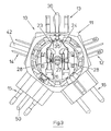
- Figure 1 is a first embodiment of an inventive electrical plug adapter 10 shown, the for optional connection of a three-pin plug system different country-specific plug-in systems with and without Protective contact is provided.
- the plug adapter 10 consists of a housing 11 on the Outside circumference several different plug systems 12 to 16 are arranged above on flattened housing sections.
- a socket pot 17 is rotatable in the center of the housing 11 stored.
- the socket pot 17 has plug-in openings 18 and 19 as in connection with the figures 19 and 20 explained later, by a locking device 20 are mostly closed.
- the socket pot 17 is intended for inserting a protective contact plug and can be set to one of the different Plug systems 12 to 16 an electrical connection to one produce the appropriate connector system, in Figure 1 to the Plug system 13, as indicated by the arrows 22.
- the socket position is used to secure the set position correspondingly in association with the individual plug systems 12 to 16 each can be locked, whereby, as in connection with FIG. 3 it can be seen the contact tongues provided for the plug socket only contact the assigned connector system and the other connector systems are without electrical contact.
- the contact tongues of the socket pot 17 with 23 and 24, and reference numeral 25 denotes the Shockproof.
- the arrangement is such that the Connector systems 12 to 16 complementary contact tongues to the have corresponding contact tongues 23 to 25.
- the locking profile 27 will resiliently opposite spring tongues 28 acted on, which are arranged on the socket pot 17.
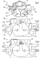
- FIGs 4 to 6 the connector system 13 is closer shown, which for the old British plug system with round Plug pins and the new British system with rectangular pins suitable is.
- 5 is that Plug system 13 with spatial assignment to the new one British connector system shown, while Figure 6 a Assignment to the old British connector system illustrated.
- Figures 5 and 6 are dotted the respective plug-opening configurations according to the new and old British system indicated.
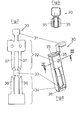
- FIG. 7 is the structure of the protective contact pin 30 shown in more detail.
- the protective contact pin 30 from a stamped sheet of sheet brass, which can be divided into subsections 31 to 34.
- the flat circuit board shown in FIG. 7 becomes the protective contact pin differently shaped in individual areas and then folded into its actual shape as shown in Figure 8.
- the area 31 is profiled in a V-shape and forms in the Housing 11 of the plug adapter 10, the contact surface for sliding contact or sliding contact bracket 25, as indicated in Figure 3.
- the areas 32 and 34 are profiled U-shaped, their Width is set so that the outer dimension of a U-profile is equal to the inside dimension of the other U-profile.
- On each of the Each leg of the two U-profiles is special Shaped resilient tongue 36 and 37 provided, the Spring tongues 36 and 37 on the folded contact plug in Circumference of a theoretical cylinder with a diameter of approx. 7 mm segment-like resilient contact surfaces for contacting in Form sockets with a round contact opening.
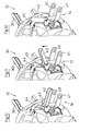
- FIGs 10 to 12 is a portion of the electrical Plug adapter 10 shown with the plug system 14.
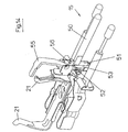
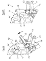
- the Plug system 14 can be from the position shown in Figure 10 into an American connector system with two flat ones Switch plugs 40 and 41, this can be a U-shaped one Protective contact pin 42, which is used to form the pin system 14 with a corresponding country-specific connector system configuration serves from the position shown in Figure 10 can be pivoted upward into contact with the housing 11, being in the region of the pivot linkage of the contact pin 42 molded cams 43 engage a locking lever 44 and this from the position shown in Figure 10 in the Figure 12 swivel.
- the plug system 14 represents a combination of an America plug with hinged protective contact pin 42. He also enables adaptation to two-pin sockets without a protective contact that still exists in some countries. In these cases, adaptation to a two-pin socket is the operation of electrical devices for safety reasons with safety plug connection, such as Travel irons, etc., are not permitted and must be used for safety reasons be prevented.
- the locking lever is used for this 44, with the protective contact pin 42 to be folded down
- the active connection is established when the protective contact pin is folded up inevitably in the socket pot 17th enters and this against insertion of a protective contact plug locks.
- Figure 13 shows the plug adapter with a forward facing Plug system 15, in which a centrally located protective contact pin 50 is designed to be vertically displaceable Plug system 15 to adapt to different insertion situations.
- Figures 15 to 18 show that of Figures 10 to 12 well-known locking mechanism for the Italian and Swiss Contact system.
- the protective contact pin 50 is as from the Figures 14 to 16 recognizable, with an angled on one side Guide part 51 provided that a lateral rotary cam 52 has that in a corresponding longitudinal guide 53 is guided in the housing.
- the angled guide part 51 serves together with the rotary cam 52 for vertical Parallel displacement, the guide member 51 in the 15 on a housing side Guide section 54 abuts and in its upper position according to FIG.
- the protective contact pin 50 is thus only in the upper end position (Swiss plug) by 90 ° upwards pivotable to the locking mechanism or the locking lever 55 actuate. In the lower end position (Italian plug) the pivoting of the protective contact pin 50 is not possible.
- the rear end of the protective contact pin 50 also has an integrally formed cam 56, which with the locking lever 55th cooperates when the safety plug 50 in the upper Swivel position is pushed.
- the locking cam 56 and that Guide part 51 form at the rear end of the plug contact pin 50 a structure similar to a beard.
- the electrical plug-in adapter 10 is shown in FIGS. 19 and 20 according to Figure 1 with the socket base half broken away shown to the locking device already mentioned in Figure 1 20 in their two positions.
- the locking device 20 consists of a fork-shaped flat slide, which via the plug contact openings 18th and 19 pushed according to FIG. 9 with the aid of a compression spring 60 is and from this position according to Figure 19 in the position according to FIG. 20 by attaching connector pins of the same length can be disengaged laterally.
- the locking lever 44 'sits in the one shown in FIG Rest position on the outside of the socket pot 17 in a downward position.
- the locking lever 44 is connected to a profiled pivot shaft 70 which in the Housing 11 'of the plug adapter 10' in a round journal bearing 21 is held, which in Figure 22 from below and in Figure 24 is shown in perspective partial section.
- the pivot shaft 70 is still guided in a housing section 72, which is formed from a sheet metal stamped part and on which the protective contact pin 42 is pivotally mounted.
- the Protective contact pin 42 has integrally formed cams 43 which in the rest position of the locking lever 44 on a side Stop profile 73 of the swivel shaft 70 and thus Secure the protective contact pin 42 against folding up.
- FIG. 26 also shows that that the locking lever 44 'in the edge-side housing recess 74 is inserted above the protective contact 21, which upper end of the protective contact 21 in an underside Deformation 75 of the locking lever 74 'is added. hereby an additional stiffening of the Support for the locking lever 44 reached.
- Figure 27 is a perspective view of the second Embodiment of the plug adapter 10 'similar to Figure 13, the connector system 15 for Switzerland and Italy is modified in that the protective contact pin 50 can only be moved vertically, but not pivotable, as in Figures 14 to 18 in the first Described embodiment. Furthermore, the Locking lever 55 dropped from the first embodiment. The Plug system 15 accordingly only allows the connection Earthing contact sockets, the earthing contact plug 50 in two positions can be moved vertically.
- one-piece construction of the Earthing contact pin 30 here consists of earthing contact pin 30 from a hollow contact pin body 30 ', which from a Sheet metal stamped part is formed and locking openings 80 and 81 has on both sides, in the angled tongues 82 to 83 are provided for fastening a spring part 30 ''.
- the Spring part 30 '' has opposite spring tongues 37 'and a rear spring tongue 36 'and is on the hollow Contact pin body 30 'can be snapped on. Otherwise, the Description of the first embodiment.
Abstract
Description
- Figur 1
- Eine Draufsicht auf ein Ausführungsbeispiel eines elektrischen Steckadapters gemäß der Erfindung;
- Figur 2
- Eine Unteransicht auf den Steckadapter gemäß Fig. 1;
- Figur 3
- Eine Draufsicht auf den Steckadapter gemäß Fig. 1, wobei der zentrale Bereich zur Verdeutlichung der Kontaktzungen und der Lagerung des Steckdosentopfes weggelassen ist;
- Figur 4
- Eine perspektivische Ansicht auf den Steckadapter gemäß Fig. 1 in Fig. 1 schräg von oben links zur Veranschaulichung eines Stecksystems, welches das alte britische Stecksystem mit runden Steckerstiften und das neue britische System mit Rechteckstiften kombiniert;
- Figur 5
- Eine Draufsicht auf das Stecksystem gemäß Fig. 4 zur Veranschaulichung, dass das Steckersystem an das neue britische Steckersystem mit Rechteckstiften passt;
- Figur 6
- Eine Ansicht gemäß Fig. 5, wobei das Passen des Steckersystems an das alte britische Stecksystem mit runden Steckerstiften veranschaulicht ist;
- Figur 7
- Eine Draufsicht auf eine aus Messingblech gestanzte Platine zur Herstellung des verschiebbaren Kontaktstifts gemäß den Fig. 4 - 6;
- Figur 8
- Eine perspektivische Einzeldarstellung eines Kontaktstiftes gemäß Fig. 4-6 im zusammengefalteten Zustand;
- Figur 9
- Einschnitt entlang der Strichlinie IX - IX in Fig. 8;
- Figur 10
- Eine perspektivische teilweise weggeschnittene Ansicht eines Steckersystems, das den Amerika-Stecker mit einem abklappbaren Schutzkontaktstift kombiniert und einen Sperrhebel aufweist;
- Figur 11
- Eine erste Verschwenkungsphase des abklappbaren Schutzkontakstiftes und bereits vollständig in den Steckdosentopf eingeschwenktem Sperrhebel;
- Figur 12
- Eine Darstellung gemäß Fig. 10, wobei der Schutzkontaktstift vollkommen abgeklappt und der Sperrhebel eingeschwenkt ist und das Einstecken eines Schutzkontaktsteckers in den Steckdosentopf verhindert;
- Figur 13
- Eine perspektivische Ansicht auf ein Steckersystem, welches das Schweizer und das italienische Steck-system vereinigt, wobei ein mittig angeordneter Schutzkontaktstift verschiebbar ausgestaltet ist;
- Figur 14
- Eine perspektivische Ansicht der Bauteile des Steck-systems gemäß Figur 13;
- Figur 15
- Eine teilweise geschnittene Seitenansicht des Stecksystems gemäß Fig. 13, das den Schutzkontaktstift in seiner untersten Stellung zeigt;
- Figur 16
- Eine Darstellung gemäß Fig. 15, wobei jedoch der Schutzkontaktstift in seiner obersten Stellung angeordnet ist;
- Figur 17
- Eine Darstellung ähnlich Fig. 16 mit halbverschwenktem Schutzkontaktstift, und bereits vollständig eingeschwenktem Sperrhebel;
- Figur 18
- Eine Darstellung ähnlich Fig. 17, wobei der Schutzkontaktstift vollständig hochgeschwenkt ist und einen Sperrhebel in den Einsteckbereich des Steckdosentopfes geschwenkt hat, um das Einstecken eines Schutzkontaktsteckers zu verhindern;
- Figur 19
- Eine Draufsicht auf den Steckadapter in einer geringfügig gedrehten Stellung zur Darstellung eines teilweise weggeschnittenen Verriegelungselements;
- Figur 20
- Eine Ansicht ähnlich Figur 19, bei der das Verriegelungselement zur Freigabe der Steckkontakte seitlich weggeschoben ist;
- Figur 21
- Eine Draufsicht auf ein zweites Ausführungsbeispiel eines elektrischen Steckadapters gemäß der Erfindung;
- Figur 22
- Eine Unteransicht des Steckadapters gemäß Figur 21;
- Figur 23
- Eine vergrößerte perspektivische teilweise weggeschnittene Ansicht eines Steckersystems, das den Amerika-Stecker mit einem abklappbaren Schutzkontaktstift kombiniert und einen modifizierten Sperrhebel aufweist;
- Figur 24
- Eine Ansicht ähnlich Figur 23, bei der der Sperrhebel hochgezogen und teilweise verschwenkt ist;
- Figur 25
- Eine Ansicht ähnlich Figur 24, wobei jedoch der Sperrhebel zu dem Steckdosentopf geschwenkt ist;
- Figur 26
- Eine Ansicht ähnlich Figur 25, bei der jedoch der Sperrhebel in einer randseitigen Gehäuseausnehmung oberhalb des Schutzkontakts am Steckdosentopf eingeschoben und der Schutzkontaktstift hochgeklappt ist;
- Figur 27
- Eine perspektivische Ansicht des Steckadapters gemäß des zweiten Ausführungsbeispiels zur Darstellung des modifizierten Schweizer und italienischen Stecksystems;
- Figur 28
- Eine vergrößerte perspektivische Darstellung der beiden Bestandteile des Schutzkontaktstifts für das alte britische und das neue britische Stecksystem;
- Figur 29
- Eine perspektivische Ansicht des Schutzkontaktstifts von Figur 28 im zusammengesetzten Zustand; und
- Figur 30
- Einen Schnitt entlang der Schnittlinie XXX-XXX in Figur 29.
Claims (17)
- Elektrischer Steckadapter (10, 10') zum wahlweisen Anschluss eines dreipoligen Stecksystems an unterschiedliche länderspezifische Stecksysteme (12-16) mit und ohne Schutzkontakt, mit
einem Gehäuse (11, 11'), an dessen Außenumfang mehrere unterschiedliche vorstehende Stecksysteme (12-16) angeordnet sind, und mit einem Steckdosentopf (17), der in dem Gehäuse (11, 11') drehbar gelagert ist und elektrische Kontakte (23, 24, 25) aufweist, die in jeweils den äußeren Stecksystemen (12-16) zugeordneten Drehstellungen des Steckdosentopfes (17) mit entsprechenden elektrischen Kontakten der jeweiligen Stecksysteme (12-16) verbindbar sind, dadurch gekennzeichnet, dass wenigstens eines der Stecksysteme (13, 14, 15) einen im Gehäuse (11, 11') bewegbar gelagerten Schutzkontaktstift (30, 42, 50) aufweist. - Steckadapter nach Anspruch 1, dadurch gekennzeichnet, dass der Schutzkontaktstift (30) für den Anschluss sowohl an das alte britische Stecksystem mit runden Steckerstiften als auch an das neue britische Stecksystem (13) mit Rechteckstiften eine Umfangsfläche mit abgerundeten und federnden Abschnitten (32, 34, 36, 37, 36', 37') aufweist.
- Steckadapter nach Anspruch 2, dadurch gekennzeichnet, dass die abgerundeten und die federnden Abschnitte (32, 34, 36, 37, 37') jeweils einander gegenüberliegen.
- Steckadapter nach Anspruch 2 oder 3, dadurch gekennzeichnet, dass der Kontaktstift(30) aus einem gestanzten zusammengefalteten Messingblech mit hohlem Innenraum geformt ist.
- Steckadapter nach einem der Ansprüche 2 bis 4, dadurch gekennzeichnet, dass die federnden Abschnitte mit Federzungen (36, 37) gebildet sind, die aus einer seitlich vorstehenden Stellung für das Einsetzen des Kontaktstiftes (30) in eine runde Kontaktöffnung beim Einsetzen in eine rechteckige Kontaktöffnung in eine Stellung in dem hohlen Innenraum bewegbar sind.
- Steckadapter nach einem der Ansprüche 2 bis 5, dadurch gekennzeichnet, dass der Kontaktstift (30) wenigstens einen abgewinkelten Führungsabschnitt (35) aufweist, der in dem Gehäuse (11, 11') zwischen zwei beabstandeten Anschlägen verschiebbar geführt ist.
- Steckadapter nach einem der vorangehenden Ansprüche, dadurch gekennzeichnet, dass weiterhin für den Anschluss an das Schweizer und das italienische Stecksystem (15) ein Stecksystem mit einem massiven verschiebbaren Schutzkontaktstift (50) vorgesehen ist.
- Steckadapter nach Anspruch 7, dadurch gekennzeichnet, dass der Schutzkontaktstift (50) an seinem hinteren Ende ein Führungsprofil (51, 56) aufweist und über seitliche Zapfen (52) in dem Gehäuse (11, 11', 53) senkrecht zu den übrigen Kontaktstiften des Stecksystems (15) verschiebbar ist.
- Steckadapter nach Anspruch 8 dadurch gekennzeichnet, dass das Führungsprofil (51) außerhalb der obersten Verschiebestellung in dem Gehäuse (11) durch ein Gehäuseanschlag (54) gegen Verschwenken gesichert ist.
- Steckadapter nach einem der vorangehenden Ansprüche, dadurch gekennzeichnet, dass durch den Schutzkontaktstift (50, 42) ein den Steckdosentopf (17) gegen ein Einstecken eines Schutzkontaktsteckers sichernder Sperrhebel (55, 44) aktivierbar und sicherbar ist.
- Steckadapter nach einem der vorangehenden Ansprüche, dadurch gekennzeichnet, dass für die Stecköffnungen (18, 19) des Steckdosentopfes (17) ein Verriegelungsmechanismus (20) vorgesehen ist, durch den die Stecköffnungen (18, 19) in den den jeweiligen Stecksystemen (12-16) zugeordneten Stellungen nur bei gleich langen und/oder gleichartigen Steckerstiften freigebbar sind.
- Steckadapter nach Anspruch 4, dadurch gekennzeichnet, dass der Kontaktstift (30) einen hohlen Kontaktstiftkörper (30') besitzt, auf dem ein Federzungen (36', 37') aufweisendes Federteil (30'') rastend (80-83) befestigt ist.
- Steckadapter nach einem der Ansprüche 1 bis 9, 11 und 12, dadurch gekennzeichnet, dass ein Sperrhebel (44') vorgesehen ist, der in seiner Sperrstellung in den Steckdosentopf (17) eingreift und ein Einstecken eines Schutzkontaktsteckers in den Steckdosentopf (17) verhindert, und der in seiner Ruhestellung außerhalb des Steckdosentopfs (17) angeordnet ist.
- Steckadapter nach Anspruch 13, dadurch gekennzeichnet, dass der Sperrhebel (44') durch eine Schub- und Schwenkbewegung aus einer Ruhestellung in seine Sperrstellung bewegbar ist.
- Steckadapter nach Anspruch 13 oder 14, dadurch gekennzeichnet, dass durch den Sperrhebel (44') in seiner Ruhestellung der Schutzkontaktstift (42) gegen ein Verschwenken gesichert ist.
- Steckadapter nach Anspruch 15, dadurch gekennzeichnet, dass der Sperrhebel (44) einen profilierten Schwenkschaft (70) aufweist, der in dem Gehäuse (11') gelagert ist und ein Anschlagprofil (73) für die Kontaktstiftnocken (43) in der Ruhestellung vorsieht.
- Steckadapter nach einem der Ansprüche 13 bis 16, dadurch gekennzeichnet, dass der Sperrhebel in einer randseitigen Gehäuseausnehmung (74) oberhalb des Schutzkontaktes (21) am Steckdosentopf (17) einschiebbar ist.
Applications Claiming Priority (2)
| Application Number | Priority Date | Filing Date | Title |
|---|---|---|---|
| DE10122620A DE10122620A1 (de) | 2001-05-10 | 2001-05-10 | Elektrischer Steckadapter |
| DE10122620 | 2001-05-10 |
Publications (2)
| Publication Number | Publication Date |
|---|---|
| EP1257018A1 true EP1257018A1 (de) | 2002-11-13 |
| EP1257018B1 EP1257018B1 (de) | 2004-05-06 |
Family
ID=7684222
Family Applications (1)
| Application Number | Title | Priority Date | Filing Date |
|---|---|---|---|
| EP02010333A Expired - Lifetime EP1257018B1 (de) | 2001-05-10 | 2002-05-07 | Elektrischer Steckadapter |
Country Status (5)
| Country | Link |
|---|---|
| US (1) | US6749451B2 (de) |
| EP (1) | EP1257018B1 (de) |
| AT (1) | ATE266268T1 (de) |
| DE (2) | DE10122620A1 (de) |
| ES (1) | ES2220855T3 (de) |
Cited By (8)
| Publication number | Priority date | Publication date | Assignee | Title |
|---|---|---|---|---|
| GB2395607A (en) * | 2002-11-19 | 2004-05-26 | Tohru Shiroshita | Two part plug adaptor |
| ES2247937A1 (es) * | 2004-08-18 | 2006-03-01 | Jacques Giribet Guadamillas | Dispositivo de carga o suministro electrico. |
| WO2007057683A1 (en) * | 2005-11-16 | 2007-05-24 | Sandal Plc | A plug converter for changing the electrical pin configuration of an appliance plug |
| WO2007080077A3 (de) * | 2006-01-07 | 2007-09-13 | Anyfix Company Gmbh | Steckdosen-ladegerät für ein elektrisches kleingerät |
| CN101390271B (zh) * | 2006-01-07 | 2011-08-03 | 万用有限公司 | 用于小型电器的插入式充电站 |
| US8142208B2 (en) | 2008-06-17 | 2012-03-27 | Walter Ruffner | Adapter plug |
| US8182276B2 (en) | 2008-06-17 | 2012-05-22 | Walter Ruffner | Multi-way sliding plug |
| US8382493B2 (en) | 2008-06-17 | 2013-02-26 | Walter Ruffner | Three-pole adapter set with a plug part and a socket part which may be plugged in the plug part |
Families Citing this family (22)
| Publication number | Priority date | Publication date | Assignee | Title |
|---|---|---|---|---|
| US7131860B2 (en) | 2003-11-20 | 2006-11-07 | Sherwood Services Ag | Connector systems for electrosurgical generator |
| TWM256005U (en) * | 2004-01-09 | 2005-01-21 | Powertech Ind Ltd | Link structure for plug |
| CN2809983Y (zh) * | 2005-04-28 | 2006-08-23 | 施鸿涛 | 多用途旅行插座 |
| TWI273752B (en) * | 2006-02-07 | 2007-02-11 | Leader Electronics Inc | Power source plug with changeable direction |
| US7604511B1 (en) | 2006-06-26 | 2009-10-20 | Johnson Steve O | Electrical adaptor |
| US7300297B1 (en) * | 2006-08-25 | 2007-11-27 | Sunfone Electronics Co. | Power supply with a changeable plug |
| US7393248B2 (en) * | 2006-11-03 | 2008-07-01 | The Boeing Company | Modular power control system with multipin connectors and airflow conrol module |
| KR100999140B1 (ko) * | 2007-12-18 | 2010-12-08 | 현대자동차주식회사 | 3극 또는 4극 전환이 가능한 멀티미디어 잭 케이블 |
| KR101049347B1 (ko) * | 2009-02-27 | 2011-07-13 | 주식회사 팬택 | 무선통신 단말기 및 이의 가이드유닛 |
| US8465310B2 (en) * | 2009-04-29 | 2013-06-18 | Ferdinand Walls, Jr. | Power cord for electrical dryers |
| TWI385875B (zh) * | 2009-10-07 | 2013-02-11 | Leader Electronics Inc | The plug can be changed in direction and replaceable power converter |
| CN102456966A (zh) * | 2010-10-26 | 2012-05-16 | 鸿富锦精密工业(深圳)有限公司 | 电连接装置及其端子 |
| TWM424681U (en) * | 2011-01-21 | 2012-03-11 | Longwell Co | Power adapter structure |
| US8579641B1 (en) * | 2011-03-14 | 2013-11-12 | Google Inc. | Multi-orientation plug |
| US8197273B1 (en) * | 2011-03-23 | 2012-06-12 | Xyz Science Co., Ltd. | German/French style plug with multiple pin arrangements |
| GB2501012B (en) * | 2011-09-16 | 2013-12-25 | Dg Int Holdings Ltd | An adaptor for adapting a mains plug and a mains cable featuring an adaptor mechanism |
| TWM426181U (en) * | 2011-09-22 | 2012-04-01 | Leader Electronics Inc | Power plug apparatus capable of changing directions |
| CN104124588B (zh) * | 2014-08-08 | 2018-11-30 | 惠州信兴荣电业塑胶有限公司 | 一种旅行转换器 |
| DE202017103748U1 (de) * | 2017-06-23 | 2018-09-26 | Weidmüller Interface GmbH & Co. KG | Anschlussvorrichtung mit veränderlicher elektrischer Verbindung zwischen Leiteranschlüssen |
| FR3068487B1 (fr) * | 2017-07-03 | 2021-05-14 | Omelcom | Support pour equipement multimedia de raccordement a un reseau etendu |
| DE102017122241A1 (de) * | 2017-09-26 | 2019-03-28 | Hans-Peter Wilfer | Steckerverbinder |
| ES2948212T3 (es) | 2018-12-21 | 2023-09-06 | Worldconnect Ag | Adaptador de viaje y conjunto que comprende un adaptador de viaje |
Citations (3)
| Publication number | Priority date | Publication date | Assignee | Title |
|---|---|---|---|---|
| DE3601469A1 (de) * | 1986-01-20 | 1987-07-23 | Kopp Gmbh & Co Kg Heinrich | Elektrisches verbindungsstueck (adapter) |
| DE19845962C1 (de) * | 1998-08-04 | 1999-10-07 | Oswald Lott | Elektrischer Steckadapter |
| DE19835161C1 (de) * | 1998-03-17 | 1999-10-28 | Oswald Lott | Mehrfachstecker für unterschiedliche Verbindungssysteme |
Family Cites Families (8)
| Publication number | Priority date | Publication date | Assignee | Title |
|---|---|---|---|---|
| IT1000801B (it) * | 1973-12-05 | 1976-04-10 | Bassani Spa | Dispositivo di sicurezza per prese di corrente elettrica |
| US4909749A (en) * | 1989-01-27 | 1990-03-20 | Jason Long | Electrical sockets |
| FR2674379B1 (fr) * | 1991-03-18 | 1993-07-16 | Legrand Sa | Adaptateur en deux parties pour appareil electrique a brancher par une fiche sur un socle de prise de courant. |
| GB9119290D0 (en) * | 1991-09-10 | 1991-10-23 | Drewnicki Richard | Electrical adaptor |
| DE4209076A1 (de) * | 1992-03-20 | 1993-09-23 | Mezger Dieter Isotronic | Reisestecker |
| US5186665A (en) * | 1992-05-15 | 1993-02-16 | General Motors Corporation | Electrical terminal |
| EP1064704B1 (de) * | 1998-03-17 | 2003-02-26 | Oswald Lott | Mehrfachstecker für unterschiedliche verbindungssysteme |
| US6419504B1 (en) * | 2001-04-17 | 2002-07-16 | Richard Bryant Nelson | Slide locked retractable grounding pin power cord plug |
-
2001
- 2001-05-10 DE DE10122620A patent/DE10122620A1/de not_active Withdrawn
-
2002
- 2002-05-07 US US10/140,461 patent/US6749451B2/en not_active Expired - Fee Related
- 2002-05-07 AT AT02010333T patent/ATE266268T1/de active
- 2002-05-07 ES ES02010333T patent/ES2220855T3/es not_active Expired - Lifetime
- 2002-05-07 DE DE50200402T patent/DE50200402D1/de not_active Expired - Lifetime
- 2002-05-07 EP EP02010333A patent/EP1257018B1/de not_active Expired - Lifetime
Patent Citations (3)
| Publication number | Priority date | Publication date | Assignee | Title |
|---|---|---|---|---|
| DE3601469A1 (de) * | 1986-01-20 | 1987-07-23 | Kopp Gmbh & Co Kg Heinrich | Elektrisches verbindungsstueck (adapter) |
| DE19835161C1 (de) * | 1998-03-17 | 1999-10-28 | Oswald Lott | Mehrfachstecker für unterschiedliche Verbindungssysteme |
| DE19845962C1 (de) * | 1998-08-04 | 1999-10-07 | Oswald Lott | Elektrischer Steckadapter |
Cited By (12)
| Publication number | Priority date | Publication date | Assignee | Title |
|---|---|---|---|---|
| GB2395607A (en) * | 2002-11-19 | 2004-05-26 | Tohru Shiroshita | Two part plug adaptor |
| GB2395607B (en) * | 2002-11-19 | 2006-01-11 | Tohru Shiroshita | Power supply conversion plug adapter |
| CN100397729C (zh) * | 2002-11-19 | 2008-06-25 | 城下工业株式会社 | 组合型电源转换插头连接器 |
| ES2247937A1 (es) * | 2004-08-18 | 2006-03-01 | Jacques Giribet Guadamillas | Dispositivo de carga o suministro electrico. |
| WO2007057683A1 (en) * | 2005-11-16 | 2007-05-24 | Sandal Plc | A plug converter for changing the electrical pin configuration of an appliance plug |
| US7867036B2 (en) | 2005-11-16 | 2011-01-11 | Sandal Plc | Plug converter for changing the electrical pin configuration of an appliance plug |
| WO2007080077A3 (de) * | 2006-01-07 | 2007-09-13 | Anyfix Company Gmbh | Steckdosen-ladegerät für ein elektrisches kleingerät |
| JP2009523403A (ja) * | 2006-01-07 | 2009-06-18 | アニフィックス カンパニイ ジーエムビーエイチ | 小型電気器具用プラグ差込み式充電ステーション |
| CN101390271B (zh) * | 2006-01-07 | 2011-08-03 | 万用有限公司 | 用于小型电器的插入式充电站 |
| US8142208B2 (en) | 2008-06-17 | 2012-03-27 | Walter Ruffner | Adapter plug |
| US8182276B2 (en) | 2008-06-17 | 2012-05-22 | Walter Ruffner | Multi-way sliding plug |
| US8382493B2 (en) | 2008-06-17 | 2013-02-26 | Walter Ruffner | Three-pole adapter set with a plug part and a socket part which may be plugged in the plug part |
Also Published As
| Publication number | Publication date |
|---|---|
| ES2220855T3 (es) | 2004-12-16 |
| US20020173187A1 (en) | 2002-11-21 |
| DE10122620A1 (de) | 2002-11-14 |
| EP1257018B1 (de) | 2004-05-06 |
| US6749451B2 (en) | 2004-06-15 |
| DE50200402D1 (de) | 2004-06-09 |
| ATE266268T1 (de) | 2004-05-15 |
Similar Documents
| Publication | Publication Date | Title |
|---|---|---|
| EP1257018B1 (de) | Elektrischer Steckadapter | |
| DE69737280T2 (de) | Gehäuse angepasst an ein Lagesicherungssystem für einen elektrischen Verbinder | |
| DE102004031110B4 (de) | Sicherungsschalter | |
| DE10224757B3 (de) | Steckverbinder mit während des Steckvorgangs verrastender Sekundärverriegelung | |
| EP1662620A2 (de) | Elektrische Steckverbindung | |
| DE102006017935A1 (de) | Steckverbindersatz | |
| DE69722867T2 (de) | Hebelartiger Steckverbinder | |
| EP3391470A1 (de) | Leiteranschlussklemme | |
| EP3671979B1 (de) | Reiseadapter sowie set umfassend einen reiseadapter | |
| EP2769441A1 (de) | Steckverbinder | |
| DE102011002135B4 (de) | Steckerelement mit zweiter Kontaktsicherung | |
| DE19849883B4 (de) | Elektrische Steckdose mit einer Kindersicherung | |
| DE102008053137B4 (de) | Steckverbindung, Stromkreis mit Steckverbindung und Betriebsverfahren | |
| DE2336216A1 (de) | Elektrische anschlussvorrichtung | |
| DE2917956A1 (de) | Wandanschlussdose | |
| DE102004008712A1 (de) | Stecker | |
| DE10131167A1 (de) | Steckverbinder | |
| EP0069045A2 (de) | Stecksockel für mehrpolige Niederspannungs-Schutzschalter | |
| DE3343661A1 (de) | Elektrischer schalter | |
| DE102006049765B4 (de) | Flachsteckbuchse für ein Kraftfahrzeug | |
| WO1989002167A1 (en) | Electric coupling device | |
| DE102013222533B4 (de) | Elektronikbox, insbesondere eine Sicherungs- oder Relaisbox für ein Kraftfahrzeug | |
| DE19739503C2 (de) | Elektrischer Steckverbinder | |
| DE19800129C2 (de) | Zigarrenanzünder-Stecker | |
| DE4139723C2 (de) | Steckdosenoberteil mit mechanischer Verriegelung |
Legal Events
| Date | Code | Title | Description |
|---|---|---|---|
| PUAI | Public reference made under article 153(3) epc to a published international application that has entered the european phase |
Free format text: ORIGINAL CODE: 0009012 |
|
| AK | Designated contracting states |
Kind code of ref document: A1 Designated state(s): AT BE CH CY DE DK ES FI FR GB GR IE IT LI LU MC NL PT SE TR |
|
| AX | Request for extension of the european patent |
Free format text: AL;LT;LV;MK;RO;SI |
|
| 17P | Request for examination filed |
Effective date: 20021017 |
|
| AKX | Designation fees paid |
Designated state(s): AT BE CH CY DE DK ES FI FR GB GR IE IT LI LU MC NL PT SE TR |
|
| 17Q | First examination report despatched |
Effective date: 20030704 |
|
| GRAP | Despatch of communication of intention to grant a patent |
Free format text: ORIGINAL CODE: EPIDOSNIGR1 |
|
| GRAS | Grant fee paid |
Free format text: ORIGINAL CODE: EPIDOSNIGR3 |
|
| GRAA | (expected) grant |
Free format text: ORIGINAL CODE: 0009210 |
|
| AK | Designated contracting states |
Kind code of ref document: B1 Designated state(s): AT BE CH CY DE DK ES FI FR GB GR IE IT LI LU MC NL PT SE TR |
|
| PG25 | Lapsed in a contracting state [announced via postgrant information from national office to epo] |
Ref country code: CY Free format text: LAPSE BECAUSE OF FAILURE TO SUBMIT A TRANSLATION OF THE DESCRIPTION OR TO PAY THE FEE WITHIN THE PRESCRIBED TIME-LIMIT Effective date: 20040506 Ref country code: IE Free format text: LAPSE BECAUSE OF FAILURE TO SUBMIT A TRANSLATION OF THE DESCRIPTION OR TO PAY THE FEE WITHIN THE PRESCRIBED TIME-LIMIT Effective date: 20040506 Ref country code: TR Free format text: LAPSE BECAUSE OF FAILURE TO SUBMIT A TRANSLATION OF THE DESCRIPTION OR TO PAY THE FEE WITHIN THE PRESCRIBED TIME-LIMIT Effective date: 20040506 Ref country code: FI Free format text: LAPSE BECAUSE OF FAILURE TO SUBMIT A TRANSLATION OF THE DESCRIPTION OR TO PAY THE FEE WITHIN THE PRESCRIBED TIME-LIMIT Effective date: 20040506 |
|
| PG25 | Lapsed in a contracting state [announced via postgrant information from national office to epo] |
Ref country code: LU Free format text: LAPSE BECAUSE OF NON-PAYMENT OF DUE FEES Effective date: 20040507 |
|
| REG | Reference to a national code |
Ref country code: GB Ref legal event code: FG4D Free format text: NOT ENGLISH |
|
| REG | Reference to a national code |
Ref country code: CH Ref legal event code: NV Representative=s name: HEPP, WENGER & RYFFEL AG Ref country code: CH Ref legal event code: EP |
|
| PG25 | Lapsed in a contracting state [announced via postgrant information from national office to epo] |
Ref country code: BE Free format text: LAPSE BECAUSE OF NON-PAYMENT OF DUE FEES Effective date: 20040531 Ref country code: MC Free format text: LAPSE BECAUSE OF NON-PAYMENT OF DUE FEES Effective date: 20040531 |
|
| REF | Corresponds to: |
Ref document number: 50200402 Country of ref document: DE Date of ref document: 20040609 Kind code of ref document: P |
|
| REG | Reference to a national code |
Ref country code: IE Ref legal event code: FG4D Free format text: GERMAN |
|
| REG | Reference to a national code |
Ref country code: SE Ref legal event code: TRGR |
|
| PG25 | Lapsed in a contracting state [announced via postgrant information from national office to epo] |
Ref country code: DK Free format text: LAPSE BECAUSE OF FAILURE TO SUBMIT A TRANSLATION OF THE DESCRIPTION OR TO PAY THE FEE WITHIN THE PRESCRIBED TIME-LIMIT Effective date: 20040806 Ref country code: GR Free format text: LAPSE BECAUSE OF FAILURE TO SUBMIT A TRANSLATION OF THE DESCRIPTION OR TO PAY THE FEE WITHIN THE PRESCRIBED TIME-LIMIT Effective date: 20040806 |
|
| GBT | Gb: translation of ep patent filed (gb section 77(6)(a)/1977) |
Effective date: 20040809 |
|
| ET | Fr: translation filed | ||
| BERE | Be: lapsed |
Owner name: HEINRICH KOPP A.G. Effective date: 20040531 |
|
| REG | Reference to a national code |
Ref country code: ES Ref legal event code: FG2A Ref document number: 2220855 Country of ref document: ES Kind code of ref document: T3 |
|
| REG | Reference to a national code |
Ref country code: IE Ref legal event code: FD4D |
|
| PLBE | No opposition filed within time limit |
Free format text: ORIGINAL CODE: 0009261 |
|
| STAA | Information on the status of an ep patent application or granted ep patent |
Free format text: STATUS: NO OPPOSITION FILED WITHIN TIME LIMIT |
|
| 26N | No opposition filed |
Effective date: 20050208 |
|
| PG25 | Lapsed in a contracting state [announced via postgrant information from national office to epo] |
Ref country code: PT Free format text: LAPSE BECAUSE OF NON-PAYMENT OF DUE FEES Effective date: 20041006 |
|
| PGFP | Annual fee paid to national office [announced via postgrant information from national office to epo] |
Ref country code: GB Payment date: 20120522 Year of fee payment: 11 |
|
| PGFP | Annual fee paid to national office [announced via postgrant information from national office to epo] |
Ref country code: CH Payment date: 20130523 Year of fee payment: 12 |
|
| PGFP | Annual fee paid to national office [announced via postgrant information from national office to epo] |
Ref country code: IT Payment date: 20130528 Year of fee payment: 12 |
|
| GBPC | Gb: european patent ceased through non-payment of renewal fee |
Effective date: 20130507 |
|
| PG25 | Lapsed in a contracting state [announced via postgrant information from national office to epo] |
Ref country code: GB Free format text: LAPSE BECAUSE OF NON-PAYMENT OF DUE FEES Effective date: 20130507 |
|
| REG | Reference to a national code |
Ref country code: CH Ref legal event code: PL |
|
| PG25 | Lapsed in a contracting state [announced via postgrant information from national office to epo] |
Ref country code: LI Free format text: LAPSE BECAUSE OF NON-PAYMENT OF DUE FEES Effective date: 20140531 Ref country code: CH Free format text: LAPSE BECAUSE OF NON-PAYMENT OF DUE FEES Effective date: 20140531 |
|
| PG25 | Lapsed in a contracting state [announced via postgrant information from national office to epo] |
Ref country code: IT Free format text: LAPSE BECAUSE OF NON-PAYMENT OF DUE FEES Effective date: 20140507 |
|
| REG | Reference to a national code |
Ref country code: FR Ref legal event code: PLFP Year of fee payment: 15 |
|
| REG | Reference to a national code |
Ref country code: FR Ref legal event code: PLFP Year of fee payment: 16 |
|
| PGFP | Annual fee paid to national office [announced via postgrant information from national office to epo] |
Ref country code: NL Payment date: 20170519 Year of fee payment: 16 |
|
| PGFP | Annual fee paid to national office [announced via postgrant information from national office to epo] |
Ref country code: FR Payment date: 20170523 Year of fee payment: 16 |
|
| PGFP | Annual fee paid to national office [announced via postgrant information from national office to epo] |
Ref country code: ES Payment date: 20170627 Year of fee payment: 16 Ref country code: SE Payment date: 20170519 Year of fee payment: 16 Ref country code: AT Payment date: 20170522 Year of fee payment: 16 |
|
| REG | Reference to a national code |
Ref country code: SE Ref legal event code: EUG Ref country code: NL Ref legal event code: MM Effective date: 20180601 |
|
| REG | Reference to a national code |
Ref country code: AT Ref legal event code: MM01 Ref document number: 266268 Country of ref document: AT Kind code of ref document: T Effective date: 20180507 |
|
| PG25 | Lapsed in a contracting state [announced via postgrant information from national office to epo] |
Ref country code: SE Free format text: LAPSE BECAUSE OF NON-PAYMENT OF DUE FEES Effective date: 20180508 Ref country code: AT Free format text: LAPSE BECAUSE OF NON-PAYMENT OF DUE FEES Effective date: 20180507 |
|
| PG25 | Lapsed in a contracting state [announced via postgrant information from national office to epo] |
Ref country code: NL Free format text: LAPSE BECAUSE OF NON-PAYMENT OF DUE FEES Effective date: 20180601 Ref country code: FR Free format text: LAPSE BECAUSE OF NON-PAYMENT OF DUE FEES Effective date: 20180531 |
|
| PGFP | Annual fee paid to national office [announced via postgrant information from national office to epo] |
Ref country code: DE Payment date: 20190531 Year of fee payment: 18 |
|
| REG | Reference to a national code |
Ref country code: ES Ref legal event code: FD2A Effective date: 20190913 |
|
| PG25 | Lapsed in a contracting state [announced via postgrant information from national office to epo] |
Ref country code: ES Free format text: LAPSE BECAUSE OF NON-PAYMENT OF DUE FEES Effective date: 20180508 |
|
| REG | Reference to a national code |
Ref country code: DE Ref legal event code: R119 Ref document number: 50200402 Country of ref document: DE |
|
| PG25 | Lapsed in a contracting state [announced via postgrant information from national office to epo] |
Ref country code: DE Free format text: LAPSE BECAUSE OF NON-PAYMENT OF DUE FEES Effective date: 20201201 |