EP1251318A2 - Dunstabzugshaubensystem - Google Patents
Dunstabzugshaubensystem Download PDFInfo
- Publication number
- EP1251318A2 EP1251318A2 EP02006137A EP02006137A EP1251318A2 EP 1251318 A2 EP1251318 A2 EP 1251318A2 EP 02006137 A EP02006137 A EP 02006137A EP 02006137 A EP02006137 A EP 02006137A EP 1251318 A2 EP1251318 A2 EP 1251318A2
- Authority
- EP
- European Patent Office
- Prior art keywords
- unit
- carrier
- filter
- electrical
- chimney
- Prior art date
- Legal status (The legal status is an assumption and is not a legal conclusion. Google has not performed a legal analysis and makes no representation as to the accuracy of the status listed.)
- Withdrawn
Links
- 238000000605 extraction Methods 0.000 title 1
- 239000000725 suspension Substances 0.000 claims abstract 3
- 230000003134 recirculating effect Effects 0.000 claims description 6
- 238000009434 installation Methods 0.000 claims description 5
- 238000011144 upstream manufacturing Methods 0.000 claims description 3
- 238000004806 packaging method and process Methods 0.000 claims 3
- OKTJSMMVPCPJKN-UHFFFAOYSA-N Carbon Chemical compound [C] OKTJSMMVPCPJKN-UHFFFAOYSA-N 0.000 claims 1
- 239000004793 Polystyrene Substances 0.000 claims 1
- 229910052799 carbon Inorganic materials 0.000 claims 1
- 239000004033 plastic Substances 0.000 claims 1
- 229920002223 polystyrene Polymers 0.000 claims 1
- 238000005253 cladding Methods 0.000 abstract description 6
- 239000002984 plastic foam Substances 0.000 abstract 1
- 239000002699 waste material Substances 0.000 abstract 1
- 239000004519 grease Substances 0.000 description 6
- 239000003517 fume Substances 0.000 description 5
- 238000003780 insertion Methods 0.000 description 3
- 230000037431 insertion Effects 0.000 description 3
- 238000004519 manufacturing process Methods 0.000 description 3
- 239000000463 material Substances 0.000 description 2
- 230000000712 assembly Effects 0.000 description 1
- 238000000429 assembly Methods 0.000 description 1
- 238000009833 condensation Methods 0.000 description 1
- 230000005494 condensation Effects 0.000 description 1
- 238000013016 damping Methods 0.000 description 1
- 238000005516 engineering process Methods 0.000 description 1
- 238000001914 filtration Methods 0.000 description 1
- 229910052736 halogen Inorganic materials 0.000 description 1
- 150000002367 halogens Chemical class 0.000 description 1
- 238000012423 maintenance Methods 0.000 description 1
- 230000003287 optical effect Effects 0.000 description 1
- 230000002093 peripheral effect Effects 0.000 description 1
- 230000008439 repair process Effects 0.000 description 1
- 238000009420 retrofitting Methods 0.000 description 1
- 239000003351 stiffener Substances 0.000 description 1
- 230000007306 turnover Effects 0.000 description 1
Images


Classifications
-
- F—MECHANICAL ENGINEERING; LIGHTING; HEATING; WEAPONS; BLASTING
- F24—HEATING; RANGES; VENTILATING
- F24C—DOMESTIC STOVES OR RANGES ; DETAILS OF DOMESTIC STOVES OR RANGES, OF GENERAL APPLICATION
- F24C15/00—Details
- F24C15/20—Removing cooking fumes
- F24C15/2071—Removing cooking fumes mounting of cooking hood
-
- F—MECHANICAL ENGINEERING; LIGHTING; HEATING; WEAPONS; BLASTING
- F24—HEATING; RANGES; VENTILATING
- F24C—DOMESTIC STOVES OR RANGES ; DETAILS OF DOMESTIC STOVES OR RANGES, OF GENERAL APPLICATION
- F24C15/00—Details
- F24C15/20—Removing cooking fumes
Definitions
- the Training chosen so that all active, necessary for the operation of the hood Devices of mechanical, electrical, electronic or electromotive type as well as their connections and vapor filters in a basic unit as a module are summarized and arranged in a tubular housing.
- the base unit has a supporting frame or a supporting housing, and can either be attached to the side wall or to the ceiling be trained.
- Such a basic unit is the same for different device types constructive structure with the same outer dimensions, so that with a relative small number of different basic units in a simple manner relatively large number of different extractor hoods can be combined can.
- there are within a predetermined basic unit However, changes are not possible, since this is the basic unit for trading or represents the smallest interchangeable unit to the consumer.
- the support unit has height and side adjustable for wall mounting Hanging devices and has a safety catch.
- this carrier unit is guides for inserting the Electrical unit provided, e.g. in the form of a housing for the electrical unit Slide-in plate that contains the electrical necessary for the operation of the extractor hood Components, e.g. Main connection cable, main board, transformer and the like. receives.
- the carrier unit takes electrical, if necessary Plug connections to other units, namely to the drive motor unit for the lighting in the filter unit and for regulation in the filter unit.
- the insert plate that receives the electrical components is designed so that it is mounted and fixed in a vibration-damping manner in the carrier unit.
- a such insertable or extractable component sheet is a problem Maintenance and a particularly simple and user-friendly pre-assembly guaranteed.
- the drive motor unit is placed on the carrier unit and screwed to it.
- the electrical connection between the motor and the board of the carrier unit is made with the help of a plug connection that is designed so that a faulty connection is excluded.
- a filter unit is connected to the underside of the carrier unit, e.g. to them screwed.
- the electrical connection between that arranged in the filter unit The lighting and the circuit board of the carrier unit are also made via a plug connection, which is designed so that a faulty connection is excluded. If the filter unit has a button control, this button control with the Board of the carrier unit connected via a corresponding plug connection.
- the electric unit of the hood according to the invention can in the case of a wall unit directly attached to the wall, or in the case of an island device using a Carrier housing, which has height-adjustable housing parts, attached to the ceiling become.
- the carrier unit or the carrier housing is designed such that it or it can accommodate the electrical unit and optionally also the drive motor unit, preferably the electrical unit and the drive motor unit from the front into the Carrier housing can be inserted.
- the carrier housing is on the ceiling e.g. fixed with the help of a special mounting plate, which is screwed to the ceiling and into which the carrier housing is inserted and screwed tight.
- a special mounting plate which is screwed to the ceiling and into which the carrier housing is inserted and screwed tight.
- the Infinitely adjustable length of the carrier housing is the Infinitely adjustable length of the carrier housing.
- the electrical unit that has the required electrical components for the operation and control of the extractor hood takes up, the insert plate, so that different insert plates with different electrical components according to the technical circumstances the trigger device can be equipped for different models, different for such equipped slide-in plates always find the same for ceiling mounting Carrier housing and in the case of wall mounting, the same wall mounting part Use.
- Such a filter unit is for example with radio remote control or with Key control equipped.
- Filter unit and vapor screen set one technical unit that cannot be separated.
- Conventional grease filters must pass through the inlet opening Air accelerator upstream, which the suction speed of the vapors before Filter increased. Immediately behind the air accelerator is the air speed again reduced in order to achieve a good filtering result in the grease filter.
- the drive motor unit is fixed directly to the electrical unit in the case of a side wall fastening or in the carrier housing when it is fastened to the ceiling, but can optionally be used as an external motor at a distance from the electrical unit in an interior of the building or in an outer wall of the building with the aid of a separate wall-mounted housing be attached.
- the drive motor unit or the motor is coupled to the electrical unit or the electrical components via a plug connection. In the event that the motor is arranged at a greater distance from the electrical unit, a cable extension is provided.
- motor units with different motor outputs but the same installation dimensions are available, e.g.
- drive motor units with air outputs of 500 m 3 / h, 800 m 3 / h or 1000 m 3 / h.
- the extractor hoods can be optionally equipped with the desired drive motor unit without the need for structural changes. Subsequent retrofitting is also possible without any problems.
- Drive motor unit and filter unit are connected to each other via an air duct that leads from the filter unit to the drive motor unit via an opening in the electrical unit.
- a backflow flap can be dispensed with become.
- a wall box is always required, which with a Backflow hatch must be fitted as close as possible to the outer wall is arranged so that the cold air does not enter the exhaust air duct and a can cause unwanted condensation.
- There is a backflow flap in recirculation mode therefore not necessary because only the indoor air is circulated and the Backflow flap would only hinder the air flow.
- the air deflection housing of the drive motor unit acts as protection and replaces it the function of the backflow flap.
- the fireplace cladding is in one embodiment according to the invention for Telescopic fireplaces formed in two parts, the upper part being designed for circulating air can and seamlessly merge different lengths.
- Another one Embodiment of a fireplace cladding with wall mounting becomes a lower part either hung at the bottom in retaining bolts, e.g. attached to the electrical unit are, or hooked into a special holding part above, so that the insertion is particularly simple and user-friendly.
- the top of the chimney cladding is guided for the lower chimney part by the retaining bolts of the holding part and fixed on top of a special additional chimney fastening part. In air recirculation mode is attached to a recirculating air switch.
- Such a structural design of an extractor fan according to the invention results in an extraordinarily high flexibility in the combination of the individual Units in positioning the drive motor unit relative to the rest Units and an extremely high degree of design freedom with regard to the optical Variants of the vapors and chimney linings.
- the customer choose from the outset a device with integrated Drive motor or with an external motor, or whether the device on the wall or to be mounted on the ceiling.
- the telescopic structure for ceiling mounting can be used later.
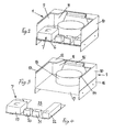
- the extractor hood system consists of a carrier unit 1 as a central unit, a drive motor unit 2, which is placed on the carrier unit 1 and connected to it, a filter unit 3 connected to the underside of the carrier unit 1 is connected, a vapor screen 4, the lower end of the filter unit 3 and connected to the filter unit 3 so that a stack of three Units 1, 2, 3 is formed.
- the carrier unit 1 is through a stable frame 5 shown, which is attached to the wall.
- a sliding plate 6 insertable which the switching and electrical unit 7 in the form of for the operation of Systems required electrical components.
- the Drive motor unit 2 is placed on the carrier unit 1 so that it is the upper Section of the carrier unit 1 encloses or encloses like a hood and with it is firmly connected by means of screw or plug connections.
- the electrical connection between the drive motor unit 2 and the board of the carrier unit 1 takes place via a connector that is designed so that connection errors are not possible.
- the filter unit 3 is screwed onto the carrier unit 1 from below.
- the electrical Connection of the lighting and the circuit board within the carrier unit with the Filter unit 3 also takes place via a fail-safe plug connection.
- the frame or the housing of the carrier unit 1 consists of Side walls 9, 10, a rear wall 11, a partial top wall 12, folds 13, 14 at the upper limit of the side walls 9 and 10, a profiled Plug connection 15 at the upper end of the rear wall, a stiffener 16 at the lower End of the two side walls 9 and 10 with fasteners, a bottom 17 and an exhaust pipe ring 18 above the floor 17.
- the electrical components 19, 20, 21, 22 are arranged on the insert plate 6 such that a recess 23 arises, which is adapted to the shape of the exhaust pipe 18, so that the plate 6 in the Carrier unit 1 can be inserted through the exhaust pipe 18 without hindrance can.
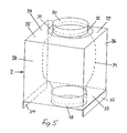
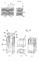
- the drive motor unit 2 shown in FIG. 5 consists of side walls 25, 26, Rear wall 27, front wall 28, top wall 29 with ring 30 for receiving one here Exhaust pipe, not shown, and with an annular flange 31 and fastening points 32 for connection to the top wall 29.
- the drive motor unit 2 also has a bottom 33 with L flanges 34, 35 as the lower extension of the side walls 25, 26, which embrace the upper part of the frame 5 of the carrier unit 1 and the Represent attachment of the drive motor unit 2 on the carrier unit 1.
- the motor the drive motor unit is indicated in unit 2 by dashed lines M.
- the drive motor unit 2 can be installed in different ways e.g. directly on the carrier unit 1 and immediately above the Switching and electrical unit 7 (as shown in Fig. 1), the connection of the Air flow between drive motor unit 2 and filter unit 3 via a rigid Connecting pipe 8 (Fig. 1) behind a chimney cladding of the extractor, the surrounds the individual units (indicated with KV in FIG. 1) and on the carrier unit 1 attached. he follows.
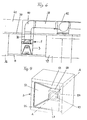
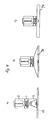
- An alternative to installing the drive motor unit in the Extractor hood system according to the invention is shown in FIG. 6.
- the drive motor unit can be used instead of anywhere in the room indicated in Fig. 6, in the manner shown in Fig. 7 so that the Drive motor unit 43 is housed in a recess in a wall wall 44.
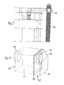
- the drive motor unit 43 is shown in FIG. 8 Formed way, namely with a pipe connection 45 for the exhaust pipe 39, a Pipe socket 46 for receiving the connecting piece of the motor M, which in a Outlet cover 47 with peripheral flange 48 passes, the cover the Shape of a shaft with a slope 49 and a lower outlet opening 50 accepts.
- the filter unit 3 is shown lying in FIG. 9 and at the bottom of the electrical unit 7 attached.
- the unit 3 in the form of a cuboid housing has one inside tapering frustoconical interior 51, 52, 53, 54, in which the Grease filters and a central halogen lighting are integrated and on the Bottom 55 of the vapor screen is attached, of different shapes and Have dimensions and can consist of different materials and the contains no electrical components.
- the filter unit for regulation provided with radio remote control there is full freedom of movement in the choice of outer shape of the fireplace and the fume screen without the filter unit technically needs to be changed.
- A-A is the axis of Fig. 1st shown.
- 56 denotes the upper end of the filter module and 57 the lamp in the filter module, which the cone down from the filter unit 3 against the Stove surface aligns.
- FIG. 11 shows three different embodiments of one Filter unit.
- the filter unit is with a flat vapor screen 69 completed
- Fig. 11b is a conventional version Suction screen 70 shown without a filter
- Fig. 11c shows one Vapor screen 71 without its own filter unit.
- An air accelerator 72 is shown in FIG Individual air accelerators 73 and 74 and a lighting arranged in between 75 shown.
- FIG. 13 shows a carrier housing for an island hood (analogous to the carrier unit 1 for a wall hood), specifically a carrier housing 76 in in FIG. 13a Exploded view, in Fig. 13b, the motor unit 2 and the electrical unit 7 and in 13c the carrier housing and motor unit in an assembled form. That below and frame frame 77 open at the front as the lower part of the carrier housing, takes one Carrier frame 78 as the upper part of the carrier housing, which has a Ceiling fastening part 79 can be fixed to the ceiling via fastening points 80.
- the insertion frame part 78 is from above on the Support frame 77 set and connected to it by side adjustment elements, such that the total height of the frame parts 77 and 78 and thus the Carrier housing is selectable.
- the support structure is transparent so that it it is possible to direct the air duct upwards or sideways, that Pull out the component sheet with the electrical components and connections and to install a recirculating air switch for recirculating air operation.
- the air diverter 85 itself is shown in FIG. 14. It is for recirculation mode screwed the wall (corresponding holes are indicated at 86), and points in its bottom surface a flange ring 87 for the air duct Exhaust air flow L up through the left and right side slot assemblies 88, 89 are each carried away in half via the switch elements 90, 91.
- the chimney top 92 is when the device in
- Exhaust mode works on a special chimney mounting part 93, which both the wall and the ceiling can be attached, screwed.
- air recirculation mode the chimney top 92 on the air diverter 85 screwed to the wall attached and stabilized and the chimney bottom 94 is at the bottom (at 95) in corresponding retaining bolts that are part of the electrical unit are hooked on.
- the Lower chimney part 94 is stabilized at the top (at 96) by a special holder 97 the bolts are fastened into which the lower chimney part 94 is hooked.
- the bracket 97 itself is screwed to the wall.
- the air diverter directs that from the engine sucked air back into the kitchen.
- the air diverter provides one gentle division and redirection of the air and avoids any backflow. she closes directly at the air outlets in the chimney.
Landscapes
- Engineering & Computer Science (AREA)
- Chemical & Material Sciences (AREA)
- Combustion & Propulsion (AREA)
- Mechanical Engineering (AREA)
- General Engineering & Computer Science (AREA)
- Ventilation (AREA)
Abstract
Description
- Fig. 1
- eine schematische Gesamtansicht des Dunstabzugssystems nach der Erfindung,
- Fig. 2
- eine Trägereinheit des Dunstabzugssystems mit einem Schalteinheit und einer Elektroeinheit nach der Erfindung in perspektivischer Ansicht,
- Fig. 3
- die Trägereinheit nach Fig. 2 ohne Schalt- und Elektroeinheit, in perspektivischer Ansicht,
- Fig. 4
- die Schalt- und Elektroeinheit nach Fig. 2, gesondert dargestellt und in perspektivischer Ansicht,
- Fig. 5
- eine Ausführungsform einer Antriebsmotor-Einheit (ohne Motor),
- Fig. 6
- eine Ausführungsform mit einer Antriebsmotor-Einheit, die außerhalb der Kaminverkleidung untergebracht ist,
- Fig. 7
- eine Ausführungsform mit einer externen Antriebsmotor-Einheit, die in eine Außenwand eingebaut ist,
- Fig. 8
- eine andere Ausführungsform einer Antriebsmotor-Eeinheit in perspektivischer Darstellung,
- Fig. 9
- eine Filtereinheit nach der Erfindung in perspektivischer Darstellung,
- Figuren 10a und 10b
- schematische Darstellungen von unterschiedlichen Luftbeschleunigern in einer Ansicht von unten,
- Figuren 11a - 11c
- schematische Darstellungen unterschiedlicher Ausführungsformen von Wrasenschirmen in Verbindung mit einer Filtereinheit in seitlicher Ansicht,
- Fig. 12
- eine schematische Darstellung eines Paares von Luftbeschleunigerelementen mit Beleuchtung, in einer Ansicht von unten,
- Figuren 13a - 13c
- eine Darstellung eines Trägergehäuses für die Deckenmontage einer Inselhaube, und zwar a) in Explosivdarstellung (ohne Antriebsmotor-Einheit), b) die Motoreinheit, c) eine zusammengebaute Anordnung aus Trägereinheit und eingesetzter Motoreinheit,
- Fig. 14
- eine Ausführungsform einer Umluftweiche, und
- Fig. 15
- einen Teleskopkamin in auseinandergezogener Darstellung mit Befestigungs-vorrichtungen.
Claims (14)
- Dunstabzugshaubensystem mit einem Gebläse zum Ansaugen des Dunststromes, einem Antriebsmotor für das Gebläse, einer Filteranordnung, durch die der angesaugte Dunststrom gesaugt und durch einen Abluftkanal durch das und aus dem Haubensystem gefördert wird, einer Schalt- und Steuervorrichtung für den Antrieb, und einem Gehäuse, das die vorgenannten Komponenten aufnimmt, dadurch gekennzeichnet, dass das Haubensystem aus einzelnen Einheiten besteht, nämlicha) einer Trägeranordnung, die an der Wand bzw. der Decke befestigt ist,b) einer von der Trägeranordnung aufgenommenen Filtereinheit,c) einer Elektroeinheit, die mit der Trägeranordnung befestigt ist und die die für den elektrischen Antrieb und die Steuerung des Haubensystems erforderlichen Elemente aufweist,d) einer Antriebsmotor-Einheit,e) einem Verbindungsrohr, das Antriebsmotor-Einheit und Filtereinheit zur Abluftführung miteinander verbindet, undf) einem Teleskopkamin in Form einer zumindest an einer der Einheiten festgelegten bzw. aufgehängten Verkleidung.
- System nach Anspruch 1, dadurch gekennzeichnet, dass die Trägeranordnung als Trägereinheit ausgebildet ist, die höhen- und seitenverstellbare Aufhängevorrichtungen zur Wandbefestigung aufweist.
- System nach Anspruch 1, dadurch gekennzeichnet, dass die Trägeranordnung als Trägergehäuse ausgebildet ist, das höhenverstellbare und teleskopartige Gehäuseteile zur Deckenbefestigung aufweist.
- System nach Anspruch 1, 2 oder 3, dadurch gekennzeichnet, dass die Trägereinheit Führungen zum Einschieben der Elektroeinheit, z.B. eines die Elektroeinheit aufnehmenden Einschubbleches aufweist.
- System nach einem der Ansprüche 1 - 4, dadurch gekennzeichnet, dass eine Motoreinheit auf die Trägereinheit aufsetzbar und befestigbar ist, und dass die Motoreinheit mit der Elektroeinheit steckbar ausgebildet ist, und dass Motoreinheiten mit unterschiedlichen Lüfterleistungen, aber gleichen Größenabmessungen als Baueinheiten auswechselbar vorgesehen sind.
- System nach einem der Ansprüche 1 - 5, dadurch gekennzeichnet, dass eine Filtereinheit an der Trägereinheit, insbesondere am Boden der Trägereinheit befestigt ist und Filtereinheit sowie Trägereinheit über ein starres Verbindungsrohr miteinander verbunden sind.
- System nach Anspruch 1 oder 5, dadurch gekennzeichnet, dass die Motoreinheit alternativ in eine Gebäudewand einsetzbar ausgebildet ist, dass ein Wandeinbauset mit Verlängerungskabel zur Verbindung der Motoreinheit mit der Elektroeinheit vorgesehen ist, und dass ein Luftführungskanal zwischen Motoreinheit und Filtereinheit vorgesehen ist.
- System nach Anspruch 1 oder 3, dadurch gekennzeichnet, dass unterhalb der Schalt- und Elektroeinheit eine Filtereinheit befestigt ist, und dass wahlweise ein separater Wrasenschirm, ein integrierter Filter im Wrasenschirm, ein Filter mit vorgeschaltetem Luftbeschleuniger, oder ein Filter-Mischtyp vorgesehen ist.
- System nach Anspruch 1, 3 oder 8, bei der die Dunstabzugshaube ein Inselgerät ist, dadurch gekennzeichnet, dass das Trägergehäuse teleskopierbar und flexibel an unterschiedliche Raum- und Montageverhältnisse anpassbar ausgebildet ist, wobei alternativ die Motoreinheit direkt auf der Schalt- und Elektroeinheit angeordnet ist, die Motoreinheit im Kamin, nicht aber direkt auf der Schalt- und Elektroeinheit aufsitzt, oder die Motoreinheit als externe Einheit befestigt ist.
- System nach Anspruch 9, dadurch gekennzeichnet, dass das Trägergehäuse mit Hilfe einer Schnellaufhängung an der Decke befestigt ist und eine an die Decke anschraubbare Befestigungsvorrichtung aufweist, in die das Trägergehäuse einschiebbar bzw. einhängbar ist, und anschließend das Trägergehäuse mit dem Befestigungsteil verschraubt wird.
- System nach einem der Ansprüche 1 - 10, dadurch gekennzeichnet, dass die Trägereinheit bzw. das Trägergehäuse transparent ist, wobei die Luftführung nach allen Seiten gerichtet werden kann, das Komponentenblech mit den elektrischen Bauteilen und Anschlüssen einschiebbar ausgebildet ist, und eine Umluftweiche für den Umluftbetrieb vorgesehen ist, die die vom Motor angesaugte Luft wieder in den Küchenraum zurückführt, wobei der Luftstrom durch die Umluftweiche symmetrisch in zwei Hälften geteilt wird.
- System nach einem der Ansprüche 1 - 11, dadurch gekennzeichnet, dass drei unterschiedliche Längen von Kaminabschnitten miteinander so kombinierbar sind, dass damit sämtliche Kaminlängen zwischen dem kürzesten Kaminabschnitt und der doppelten Länge der beiden längsten Kaminabschnitte reproduzierbar sind.
- System nach einem der Ansprüche 1 - 12, dadurch gekennzeichnet, dass das Kaminoberteil an einem gesonderten Kaminbefestigungsteil festlegbar ist, das mittels Bolzen an der Wand befestigbar ist, und dass das Kaminunterteil, z.B. über entsprechende Haltebolzen, mit der Steuer- und Elektroeinheit verbindbar ist.
- System zum Verpacken und Versenden von Dunstabzugshauben nach den Ansprüchen 1 - 13, dadurch gekennzeichnet, dass jedes Modul für sich, nämlich eine Schalt- und Elektroeinheit, eine Motoreinheit, eine Filtereinheit, ein Wrasenschirm, eine Trägereinheit, ein Abluft-Teleskopkamin, ein Umluft-Teleskopkamin, ein Wandeinbauset für die Motoreinheit, ein Verlängerungskabel für den Motoranschluss, und eine Kohlefiltereinheit in einer auf die Dimensionen der jeweiligen Einheit abgestellten Verpackungseinheit verpackt, bereitgestellt und geliefert wird, wobei die einzelnen Verpackungseinheiten aus Faltkartonteilen (ohne Stypropor oder vergleichbare Füllelemente aus Kunststoff) besteht, und dass die Kartonelemente zu einem Karton so zusammengesetzt sind, dass der Karton beim Transport um beliebige Achsen drehbar ist, ohne dass seine Stabilität reduziert wird.
Applications Claiming Priority (2)
| Application Number | Priority Date | Filing Date | Title |
|---|---|---|---|
| DE2001118881 DE10118881A1 (de) | 2001-04-18 | 2001-04-18 | Dunstabzugshaubensystem |
| DE10118881 | 2001-04-18 |
Publications (2)
| Publication Number | Publication Date |
|---|---|
| EP1251318A2 true EP1251318A2 (de) | 2002-10-23 |
| EP1251318A3 EP1251318A3 (de) | 2004-03-03 |
Family
ID=7681770
Family Applications (1)
| Application Number | Title | Priority Date | Filing Date |
|---|---|---|---|
| EP02006137A Withdrawn EP1251318A3 (de) | 2001-04-18 | 2002-03-19 | Dunstabzugshaubensystem |
Country Status (2)
| Country | Link |
|---|---|
| EP (1) | EP1251318A3 (de) |
| DE (1) | DE10118881A1 (de) |
Cited By (13)
| Publication number | Priority date | Publication date | Assignee | Title |
|---|---|---|---|---|
| EP1918646A1 (de) * | 2006-10-30 | 2008-05-07 | Elica S.P.A. | Funktionelle Struktur für Abzugshauben |
| WO2008135346A1 (de) * | 2007-05-07 | 2008-11-13 | BSH Bosch und Siemens Hausgeräte GmbH | Dunstabzugsgehäuse und dunstabzugshaube |
| WO2008129352A3 (en) * | 2006-10-30 | 2009-05-28 | Elica Spa | Functional structure for extractor hoods |
| WO2009077285A3 (de) * | 2007-12-18 | 2010-04-08 | BSH Bosch und Siemens Hausgeräte GmbH | Ausziehbare dunstabzugshaube |
| CN101858612A (zh) * | 2010-02-10 | 2010-10-13 | 李红衫 | 伸缩式排油烟柜 |
| WO2011020803A1 (de) * | 2009-08-21 | 2011-02-24 | BSH Bosch und Siemens Hausgeräte GmbH | Innenrahmen für dunstabzugshaube und dunstabzugshaube |
| KR20120050454A (ko) * | 2009-08-21 | 2012-05-18 | 베에스하 보쉬 운트 지멘스 하우스게랫테 게엠베하 | 배출기 후드, 배출기 후드용 키트 및 배출기 후드 조립 방법 |
| EP2754965A1 (de) * | 2013-01-11 | 2014-07-16 | Miele & Cie. KG | Dunstabzugshaube, insbesondere Inselhaube |
| EP2754966A1 (de) * | 2013-01-11 | 2014-07-16 | Miele & Cie. KG | Dunstabzugshaube, insbesondere Inselhaube |
| EP2827067A3 (de) * | 2013-07-15 | 2015-09-09 | BSH Hausgeräte GmbH | Zentralrahmen für Dunstabzugshaube und Dunstabzugshaube |
| EP2700882A3 (de) * | 2012-08-23 | 2017-07-12 | BSH Hausgeräte GmbH | Luftreinigereinheit einer Dunstabzugsvorrichtung |
| CN110553293A (zh) * | 2019-09-09 | 2019-12-10 | 浙江玉禾电器有限公司 | 一种吸油烟机风管罩及其安装方法 |
| WO2022228910A1 (de) * | 2021-04-27 | 2022-11-03 | BSH Hausgeräte GmbH | Gebläsegehäuse für ein gebläse einer dunstabzugsvorrichtung und gebläse für dunstabzugsvorrichtung |
Families Citing this family (5)
| Publication number | Priority date | Publication date | Assignee | Title |
|---|---|---|---|---|
| DE20316130U1 (de) * | 2003-10-21 | 2004-04-15 | BSH Bosch und Siemens Hausgeräte GmbH | Satz von Schubladen-Dunstabzugshauben |
| DE102006008804A1 (de) * | 2006-02-25 | 2007-08-30 | O + F A-Line Gmbh | Dunsthaubenturm, Deckenrahmen zum Anschluss eines Dunsthaubenturmes, sowie Dunstabzugshaubeneinrichtung |
| DE102008023311A1 (de) | 2008-05-13 | 2009-11-19 | BSH Bosch und Siemens Hausgeräte GmbH | Umluftweiche sowie Verfahren zum Montieren einer Umluftweiche |
| DE102008047155B4 (de) * | 2008-09-12 | 2014-12-31 | Miele & Cie. Kg | Befestigungssystem mit einer mehrteiligen kastenförmigen Tragstruktur |
| DE102024204103A1 (de) | 2024-05-02 | 2025-11-06 | BSH Hausgeräte GmbH | Umluftweiche für Dunstabzugshaube und Dunstabzugshaube |
Citations (5)
| Publication number | Priority date | Publication date | Assignee | Title |
|---|---|---|---|---|
| EP0146722A1 (de) | 1983-12-17 | 1985-07-03 | JASO Möbelwerke GmbH | Dunstabzugsvorrichtung für Küchen |
| DE4105004A1 (de) | 1991-02-19 | 1992-08-20 | Kueppersbusch | Dunstabzug |
| US5421320A (en) | 1994-05-27 | 1995-06-06 | Ldi Mfg. Co., Inc. | Conveyor oven exhaust system |
| US5941235A (en) | 1995-08-03 | 1999-08-24 | Garland Commercial Ranges Limited | Exhaust unit with ventless hood |
| EP0974790A2 (de) | 1998-07-18 | 2000-01-26 | SiriusDunstabzugsgeräte GmbH | Dunstabzugshauben-System |
-
2001
- 2001-04-18 DE DE2001118881 patent/DE10118881A1/de not_active Withdrawn
-
2002
- 2002-03-19 EP EP02006137A patent/EP1251318A3/de not_active Withdrawn
Patent Citations (5)
| Publication number | Priority date | Publication date | Assignee | Title |
|---|---|---|---|---|
| EP0146722A1 (de) | 1983-12-17 | 1985-07-03 | JASO Möbelwerke GmbH | Dunstabzugsvorrichtung für Küchen |
| DE4105004A1 (de) | 1991-02-19 | 1992-08-20 | Kueppersbusch | Dunstabzug |
| US5421320A (en) | 1994-05-27 | 1995-06-06 | Ldi Mfg. Co., Inc. | Conveyor oven exhaust system |
| US5941235A (en) | 1995-08-03 | 1999-08-24 | Garland Commercial Ranges Limited | Exhaust unit with ventless hood |
| EP0974790A2 (de) | 1998-07-18 | 2000-01-26 | SiriusDunstabzugsgeräte GmbH | Dunstabzugshauben-System |
Cited By (18)
| Publication number | Priority date | Publication date | Assignee | Title |
|---|---|---|---|---|
| WO2008129352A3 (en) * | 2006-10-30 | 2009-05-28 | Elica Spa | Functional structure for extractor hoods |
| EP1918646A1 (de) * | 2006-10-30 | 2008-05-07 | Elica S.P.A. | Funktionelle Struktur für Abzugshauben |
| WO2008135346A1 (de) * | 2007-05-07 | 2008-11-13 | BSH Bosch und Siemens Hausgeräte GmbH | Dunstabzugsgehäuse und dunstabzugshaube |
| WO2009077285A3 (de) * | 2007-12-18 | 2010-04-08 | BSH Bosch und Siemens Hausgeräte GmbH | Ausziehbare dunstabzugshaube |
| CN102472505B (zh) * | 2009-08-21 | 2015-12-16 | Bsh家用电器有限公司 | 用于排烟罩的内部框架和排烟罩 |
| WO2011020803A1 (de) * | 2009-08-21 | 2011-02-24 | BSH Bosch und Siemens Hausgeräte GmbH | Innenrahmen für dunstabzugshaube und dunstabzugshaube |
| KR20120050454A (ko) * | 2009-08-21 | 2012-05-18 | 베에스하 보쉬 운트 지멘스 하우스게랫테 게엠베하 | 배출기 후드, 배출기 후드용 키트 및 배출기 후드 조립 방법 |
| CN102472505A (zh) * | 2009-08-21 | 2012-05-23 | Bsh博世和西门子家用电器有限公司 | 用于排烟罩的内部框架和排烟罩 |
| EP2467648B1 (de) * | 2009-08-21 | 2017-12-13 | BSH Hausgeräte GmbH | Dunstabzugshaube und verfahren zur montage einer dunstabzugshaube |
| EA025119B1 (ru) * | 2009-08-21 | 2016-11-30 | Бсх Хаусгерете Гмбх | Вытяжной колпак |
| CN101858612A (zh) * | 2010-02-10 | 2010-10-13 | 李红衫 | 伸缩式排油烟柜 |
| EP2700882A3 (de) * | 2012-08-23 | 2017-07-12 | BSH Hausgeräte GmbH | Luftreinigereinheit einer Dunstabzugsvorrichtung |
| EP2754966A1 (de) * | 2013-01-11 | 2014-07-16 | Miele & Cie. KG | Dunstabzugshaube, insbesondere Inselhaube |
| EP2754965A1 (de) * | 2013-01-11 | 2014-07-16 | Miele & Cie. KG | Dunstabzugshaube, insbesondere Inselhaube |
| EP2827067A3 (de) * | 2013-07-15 | 2015-09-09 | BSH Hausgeräte GmbH | Zentralrahmen für Dunstabzugshaube und Dunstabzugshaube |
| CN110553293A (zh) * | 2019-09-09 | 2019-12-10 | 浙江玉禾电器有限公司 | 一种吸油烟机风管罩及其安装方法 |
| CN110553293B (zh) * | 2019-09-09 | 2024-02-23 | 浙江玉禾电器有限公司 | 一种吸油烟机风管罩及其安装方法 |
| WO2022228910A1 (de) * | 2021-04-27 | 2022-11-03 | BSH Hausgeräte GmbH | Gebläsegehäuse für ein gebläse einer dunstabzugsvorrichtung und gebläse für dunstabzugsvorrichtung |
Also Published As
| Publication number | Publication date |
|---|---|
| EP1251318A3 (de) | 2004-03-03 |
| DE10118881A1 (de) | 2002-11-07 |
Similar Documents
| Publication | Publication Date | Title |
|---|---|---|
| EP1251318A2 (de) | Dunstabzugshaubensystem | |
| EP3504483B1 (de) | Kombinationsgerät und eine küchenvorrichtung mit kombinationsgerät | |
| DE20005154U1 (de) | Dunstabzugshaube | |
| DE102008033792A1 (de) | Umluftmodul und Dunstabzugsvorrichtung | |
| EP2156100B1 (de) | Dunstabzugsgehäuse und dunstabzugshaube | |
| EP1331982B1 (de) | Haube für einen filterlüfter | |
| EP3338031A1 (de) | Kombinationsgerät mit kochfeld und dunstabzugsvorrichtung | |
| EP0974790B1 (de) | Dunstabzugshauben-System | |
| EP3710756B1 (de) | Dunstabzugsvorrichtung für ein kochfeld und küchenmöbel mit dunstabzugsvorrichtung | |
| DE102008041739A1 (de) | Dunstabzugsvorrichtung | |
| EP3710755B1 (de) | Dunstabzugsvorrichtung für ein kochfeld und küchenmöbel mit dunstabzugsvorrichtung | |
| EP2467649B1 (de) | Dunstabzugshaube | |
| EP2210048B1 (de) | Dunstabzugsvorrichtung | |
| DE19838648B4 (de) | Dunstabzugshauben-System | |
| EP3101350B1 (de) | Lüftereinheit für dunstabzugshaube und dunstabzugshaube | |
| EP2467648B1 (de) | Dunstabzugshaube und verfahren zur montage einer dunstabzugshaube | |
| WO2009101099A1 (de) | Dunstabzugssystem mit separatem filtergehäuse | |
| EP0886112A2 (de) | Kombinierte Klimatisier- und Dunsthaube | |
| DE102010063860A1 (de) | Dunstabzugshaube | |
| DE10000841B4 (de) | Dunstabzugshaube | |
| EP2554915B1 (de) | Dunstabzugshaube mit filterträger und geruchsfilterelement | |
| EP2827067B1 (de) | Dunstabzugshaube | |
| EP3819549A1 (de) | Dunstabzugsvorrichtung für ein küchengerät | |
| EP0982548B1 (de) | Dunstabzugs-Profilsystem | |
| EP0499813B1 (de) | Gehäuse zur Aufnahme eines Gebläses |
Legal Events
| Date | Code | Title | Description |
|---|---|---|---|
| PUAI | Public reference made under article 153(3) epc to a published international application that has entered the european phase |
Free format text: ORIGINAL CODE: 0009012 |
|
| AK | Designated contracting states |
Kind code of ref document: A2 Designated state(s): AT BE CH CY DE DK ES FI FR GB GR IE IT LI LU MC NL PT SE TR |
|
| AX | Request for extension of the european patent |
Free format text: AL;LT;LV;MK;RO;SI |
|
| PUAL | Search report despatched |
Free format text: ORIGINAL CODE: 0009013 |
|
| AK | Designated contracting states |
Kind code of ref document: A3 Designated state(s): AT BE CH CY DE DK ES FI FR GB GR IE IT LI LU MC NL PT SE TR |
|
| AX | Request for extension of the european patent |
Extension state: AL LT LV MK RO SI |
|
| 17P | Request for examination filed |
Effective date: 20040831 |
|
| AKX | Designation fees paid |
Designated state(s): AT BE CH CY DE DK ES FI FR GB GR IE IT LI LU MC NL PT SE TR |
|
| RAP1 | Party data changed (applicant data changed or rights of an application transferred) |
Owner name: SILBER, GERHARD |
|
| 17Q | First examination report despatched |
Effective date: 20080602 |
|
| STAA | Information on the status of an ep patent application or granted ep patent |
Free format text: STATUS: THE APPLICATION IS DEEMED TO BE WITHDRAWN |
|
| 18D | Application deemed to be withdrawn |
Effective date: 20121002 |