EP1239345A1 - Tonerrückgewinnungsvorrichtung zur wirksamen Beseitigung von Fremdstoffen und der Agglomeration von Toner - Google Patents
Tonerrückgewinnungsvorrichtung zur wirksamen Beseitigung von Fremdstoffen und der Agglomeration von Toner Download PDFInfo
- Publication number
- EP1239345A1 EP1239345A1 EP02004395A EP02004395A EP1239345A1 EP 1239345 A1 EP1239345 A1 EP 1239345A1 EP 02004395 A EP02004395 A EP 02004395A EP 02004395 A EP02004395 A EP 02004395A EP 1239345 A1 EP1239345 A1 EP 1239345A1
- Authority
- EP
- European Patent Office
- Prior art keywords
- toner
- filter
- brush
- recovery
- recovery toner
- Prior art date
- Legal status (The legal status is an assumption and is not a legal conclusion. Google has not performed a legal analysis and makes no representation as to the accuracy of the status listed.)
- Granted
Links
Images


Classifications
-
- G—PHYSICS
- G03—PHOTOGRAPHY; CINEMATOGRAPHY; ANALOGOUS TECHNIQUES USING WAVES OTHER THAN OPTICAL WAVES; ELECTROGRAPHY; HOLOGRAPHY
- G03G—ELECTROGRAPHY; ELECTROPHOTOGRAPHY; MAGNETOGRAPHY
- G03G21/00—Arrangements not provided for by groups G03G13/00 - G03G19/00, e.g. cleaning, elimination of residual charge
- G03G21/10—Collecting or recycling waste developer
- G03G21/105—Arrangements for conveying toner waste
Definitions
- the present invention relates to a recovery toner classifier to be used in an image forming apparatus, such as a copying machine, a facsimile, a printer, and other similar devices, and more particularly to a recovery toner classifier that can effectively classify recovery toner into toner to be reused and toner to be disposed of.
- An image forming apparatus generally includes a cleaning device.
- the cleaning device is provided to recover residual toner remaining on an image bearing member, such as a photoconductive element and intermediate transfer belt after a toner image has been transferred onto a transfer sheet.
- the cleaning device is also provided to a sheet conveying device, which conveys the transfer sheet having the toner image thereon to a fixing device, to recover unfixed toner (i.e., residual toner).
- Fig. 11 is a schematic drawing illustrating a sectional view of a toner recycle device, components arranged around a photoconductive drum, and a recovery toner conveying path in a back ground image forming apparatus.
- a charging device 17, a cleaning device 18, a developing device 19, and a transfer device 20 are arranged around a photoconductive drum 16.
- a recovery toner conveying mechanism 21 is provided between the cleaning device 18 and developing device 19.
- recovery toner is conveyed into the recovery toner classifier.
- a recovery toner replenishing roller then presses the recovery toner disposed on the filter to crush the aggregation of toner.
- the toner passes through the filter is conveyed to the developing device for reuse.
- the filter is provided in the midst of a recovery toner conveying path.
- a disposal toner conveying path is provided below the filter.
- the recovery toner conveyed through a recovery toner conveying path is conveyed into a cylindrical-shaped filter.
- the filter is then vibrated to classify the recovery toner into toner to be reused and to be disposed of.
- the present invention has been made in view of the above-mentioned and other problems and addresses the above-discussed and other problems.
- the object of the present invention is to provide a novel recovery toner classifier that can effectively remove a foreign substance such as paper lint included in recovery toner and crush an aggregation of toner in the recovery toner.
- the recovery toner classifier comprises preferably a filter member which allows in particular to filter toner such that preferably only toner (a "second portion" of toner, see below) of a predetermined size and/or mass or below passes the filter member (while a "first portion” of the toner does not pass the filter member).
- the process of classifying in particular includes the separation of toner in the first and second portion.
- the recovery toner classifier comprises a toner inlet for the recovery toner to be classified.
- the recovery toner classifier comprises preferably a toner outlet for a first portion of the recovery toner, said first portion representing toner which is to be disposed.
- a filtering mechanism is preferably provided.
- the filtering mechanism preferably conveys the toner from the toner inlet to the toner outlet, urges the toner towards the filter member for causing a second portion of the toner, i.e. a toner to be recycled, to penetrate through the filter member, and/or contacts the filter member.
- the contact between the filtering mechanism and the filter member is in particular part of a relative movement between the filter member and the filtering mechanism.
- the contact is in particular a sliding contact or the filtering mechanism slidingly rubs the filter member.
- the filtering mechanism comprises in particular a brush member or another member which allows movement of toner particles along filaments or other predefined paths (e.g.
- the recovery toner which passes the recovery toner classifier may be conveyed and/or may be moved due to a gravitational force acting on the toner (in particular in case the toner outlet is arranged below the toner inlet).
- a toner conveying mechanism is provided externally or as a part of the filtering mechanism said toner conveying mechanism causing the movement of the recovered toner from the toner inlet to the toner outlet.
- a passage is provided which allows movement of the recovery toner toward the outlet, preferably parallel to the contact surface between the filtering member and the filter member.
- this passage is located distant from the contact surface.
- the filter member and/or the filtering mechanism is rotated and preferably, the passage is close to the rotational axis or correspondence to the rotational axis of the filter member and/or filtering mechanism.
- the passage is connected with the afore-mentioned predefined paths of the filter mechanism in order to allow toner to move from the passage via the predefined paths to the filter member.
- the paths are inclined with respect to the passage (e.g.
- the movement along the predefined paths is caused by the filtering mechanism, e.g. by a centrifugal force, e.g. assisted by the gravitational force.
- the filter member is of cylindrical shape and the toner inlet and toner outlet are at the flat surface ends of the cylinder, respectively.
- the toner to be recycled is output towards and/or through the filter member in a direction which is at least approximately and/or at least partly perpendicular to the passage path of the recovery toner from the toner inlet to the toner outlet.
- filtering mechanism is a brush mechanism which may be for instance a rotatable fur brush or e.g. any other kind of brush with elastic filaments.
- the recovery toner classifier includes rotatable a cylindrical-shaped filter having an inlet for the recovery toner at one end of the filter in a direction of length and an outlet for discharging the disposal toner at the other end of the filter, and a fur brush having a brush spirally provided on an outer peripheral surface of a rotation shaft and a non-brush region continuously formed from the inlet of the filter for the recovery toner through the outlet of the filter for discharging the disposal toner along the axis line of the rotation shaft.
- the fur brush is concentrically contained in the filter such that the fur brush integrally rotates with the rotation shaft with a tip portion of the brush is in press-contact with an inner peripheral surface of the filter.
- a screw conveyer having a screw provided on a portion of the rotation shaft on a side of the inlet of the filter for the recovery toner is arranged to convey the recovery toner to the inlet of the filter for the recovery toner.
- Fig. 1 is a schematic drawing illustrating a sectional view of a toner recycle device 100 including the recovery toner classifier 1.
- Fig. 1 further illustrates main components arranged around the photoconductive drum 16 in an image forming apparatus in which the recovery toner classifier 1 is incorporated.
- Fig. 2 is a drawing illustrating a longitudinal sectional view of the recovery toner classifier 1.
- Fig. 3 is a drawing illustrating a perspective view of a main construction of the recovery toner classifier 1.
- Figs. 4A and 4B drawings illustrating an example of a fur brush 3 of the recovery toner classifier 1.
- Fig. 1 is a schematic drawing illustrating a sectional view of a toner recycle device 100 including the recovery toner classifier 1.
- Fig. 1 further illustrates main components arranged around the photoconductive drum 16 in an image forming apparatus in which the recovery toner classifier 1 is incorporated.
- Fig. 2 is a drawing illustrating a longitudinal sectional view of the recovery toner classifier 1.
- FIG. 4A is a longitudinal sectional view of the fur brush 3.
- Fig. 4B is a sectional view of the fur brush 3 cut along a line indicated by "A-A" in Fig. 4A.
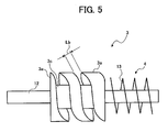
- Fig. 5 is a drawing illustrating another example of the fur brush 3.
- Fig. 6 is a drawing illustrating a sectional view of the recovery toner classifier 1 when the recovery toner classifier 1 is operated.
- Fig. 7 is a drawing illustrating a sectional view of the recovery toner classifier 1 when the recovery toner classifier 1 is operated in a different manner.
- the charging device 17, cleaning device 18, developing device 19, and transfer device 20 are arranged around the photoconductive drum 16.
- the cleaning device 18 includes a cleaning blade 18a and brush roller 18b. These cleaning members are provided to remove residual toner remaining on a surface of the photoconductive drum 16 after a toner image has been transferred onto a transfer sheet (not shown).
- the developing device 19 develops an electrostatic latent image formed on the surface of the photoconductive drum 16 into a toner image with a developer including toner and a carrier.
- the developing device 19 includes a developing roller 19a (e.g., developing sleeve) and agitation paddle 19b.
- the developing roller 19a rotates in a same direction in which the photoconductive drum 16 rotates.
- the agitation paddle 19b agitates the developer.
- the transfer device 20 includes a transfer belt 20a that transfers the toner image formed on the surface of the photoconductive drum 16 onto a transfer sheet (not shown).
- the recovery toner classifier 1 is arranged above the developing device 19.
- the recovery toner conveying mechanism 21 (e.g., a screw conveyer) is provided between the cleaning device 18 and developing device 19.
- the recovery toner conveying mechanism 21 includes a rotating shaft and a screw blade 25 that is provided to the rotating shaft.
- the recovery toner conveying mechanism 21 is rotatable in a recovery toner conveying pipe 24.
- the recovery toner conveying mechanism 21 forms a recovery toner conveying path.
- the recovery toner conveying path includes a first recovery toner conveying path 25a and second recovery toner conveying path 25b. One end of the first recovery toner conveying path 25a is connected to the cleaning device 18.
- the recovery toner classifier 1 is provided between an end of the recovery toner conveying mechanism 21 and the developing device 19.
- the recovery toner classifier 1 is provided in a toner conveying path arranged at an upper portion of the developing device 19.
- a disposal toner conveying path 22 is branched off from the toner conveying path.
- the disposal toner conveying path 22 is connected to a disposal toner container 23.
- An inlet 5 of the recovery toner classifier 1 is connected to the end of the recovery toner conveying mechanism 21.
- An outlet 6 of the recovery toner classifier 1 is connected to the disposal toner conveying path 22, and an opening of the recovery toner classifier 1 is connected to the developing device 19 (see Fig. 2).
- Recovery toner T recovered from a surface of the photoconductive drum 16 by the cleaning device 18 is conveyed to the recovery toner classifier 1 through the first and second recovery toner conveying paths 25a and 25b.
- the recovery toner T conveyed into the recovery toner classifier 1 is classified into recycled toner Ta and disposal toner Tb.
- the recycled toner Ta is reused by the developing device 19.
- the disposal toner Tb is conveyed to the disposal toner container 23 through the disposal toner conveying path 22. The disposal toner Tb is then disposed of.
- Fig. 1 when an image forming operation is started, the photoconductive drum 16 is rotated by a driving motor (not shown). A surface of the photoconductive drum 16 is uniformly charged by the charging device 17. An electrostatic latent image is then formed on the surface of the photoconductive drum 16. The electrostatic latent image is developed into a toner image by the developing device 19 with a developer. The toner image is transferred onto the rotating transfer belt 20a (i.e., primary transfer). The toner image is then transferred onto a transfer sheet (not shown) fed from a sheet feeding device (i.e., second transfer). The transfer sheet is conveyed to a fixing device where the toner image is fixed onto the transfer sheet.
- a driving motor not shown
- a surface of the photoconductive drum 16 is uniformly charged by the charging device 17.
- An electrostatic latent image is then formed on the surface of the photoconductive drum 16.
- the electrostatic latent image is developed into a toner image by the developing device 19 with a developer.
- the toner image is transferred onto the rotating transfer belt 20
- Unfixed toner on the transfer sheet is offset on the surface of the photoconductive drum 16.
- the conductive brush roller 18b discharges the offset toner to recover the toner by the cleaning blade 18a.
- the recovery toner is conveyed to the recovery toner classifier 1 by the recovery toner conveying mechanism 21 through the first and second recovery toner conveying paths 25a and 25b.
- the recovery toner classifier 1 includes a main body 2 of the recovery toner classifier 1.
- the main body 2 includes a cylindrical-shaped filter 9 formed of a mesh (i.e., a net member) or sieve or porous foil and the fur brush 3 that slidingly rubs the filter 9.
- An inlet 5a for recovery toner is formed at one end of the filter 9 in the direction of the length while the outlet 6 for disposal toner is formed at the other end of the filter 9.
- a finess of the mesh of the filter 9 (i.e., a size of the mesh) is set such that paper lint and aggregation of toner, which are larger than predetermined sizes, are not passed through the mesh.
- the toner that does not pass through the filter 9 is discharged from the outlet 6.
- the filter 9 includes a main body of filter 9a (also called filter member 9a) formed of metallic or resin wire member and a frame 10 formed of resin.
- the main body of filter 9a is fixedly provided to an inner peripheral surface of the frame 10.
- the frame 10 holds the main body of filter 9a.
- a power transmission member 11 such as a gear is connected to one end of the frame 10.
- a rotation driving mechanism of the filter 9 includes the power transmission member 11 and a power transmission member (not shown) provided to a shaft of a driving motor.
- filter 9 rotates integrally with the frame 10.
- the fur brush 3 includes a brush 3a that is radially provided on an outer peripheral surface of the rotation shaft 12 in a direction perpendicular to the outer peripheral surface of the rotation shaft 12.
- the filter 9 concentrically contains the fur brush 3.
- a tip end of the brush 3a is in press-contact with a mesh of the filter 9.
- a diameter of fur brush 3 and a length of the brush 3a are set to 26mm and 6mm, respectively.
- the brush 3a is not provided on an entire outer peripheral surface of the rotation shaft 12. Thus, a non-brush region is continuously formed on the outer peripheral surface of the rotation shaft 12 from the inlet 5a through the outlet 6 along an axis line of the rotation shaft 12.
- Figs. 4A, 4B, and 5 are drawings illustrating a construction of the fur brush 3 having the above-described non-brush region.
- a non-brush region 3b is continuously arranged from the inlet 5a through the outlet 6 in a parallel direction to the axis line of the rotation shaft 12.
- a width La of the non-brush region 3b is set, for example, to 6mm.
- the brush 3a is spirally provided on the outer peripheral surface of the rotation shaft 12 having a predetermined space in-between.
- a non-brush region 3c is spirally and continuously formed on the outer peripheral surface of the rotation shaft 12 from the inlet 5a through the outlet 6 along the axis line of the rotation shaft 12.
- a width Lb of the non-brush region 3c is set, for example, to 6mm.
- An inlet tube 4a surrounds a lower half portion of a screw conveyer 4.
- the screw conveyer 4 includes a screw blade 13 provided to a portion of the rotation shaft 12 on the side of the inlet 5a.
- a size of the mesh of the filter 9 is, for example, set to approximately 200 meshes.
- the frame is formed of a resin mold, such as polyacetal and polybutyleneterephthalate.
- the filter 9 and fur brush 3 rotate in the same direction or in a different direction. When the filter 9 and fur brush 3 rotate in the same direction, they rotate at a different circumferential velocity. When the filter 9 and fur brush 3 rotate in a different direction, they rotate at a different circumferential velocity or at the same circumferential velocity.
- Fig. 6 is a drawing illustrating the filter 9 and fur brush 3 rotating in the same direction at a different circumferential velocity.
- Fig. 7 is a drawing illustrating the filter 9 and fur brush 3 rotating in a different direction.
- the recovery toner T in the non-brush region 3b is conveyed toward the outlet 6 while being pushed by a following recovery toner T in an axis line direction of the rotation shaft 12.
- a classification process of the recovery toner T is performed during the above-described conveyance of the recovery toner T.
- the recovery toner T moves to the mesh of the filter 9 by a centrifugal force generated by a rotation of the fur brush 3.
- Toner having a small diameter passes through the mesh of the filter 9.
- the toner is then discharged from the opening 8 so that the toner is conveyed to the developing device 19.
- the brush 3a pushes the recovery toner T against the mesh of the filter 9 while brushing the mesh of the filter with a tip portion thereof such that the toner having a small diameter passes through the mesh of the filter 9.
- a portion of the fur brush 3 other than the tip portion of the brush 3a also brushes toner and paper lint. Large paper lint, which does not pass through the mesh of the filter 9, is conveyed to the outlet 6. The large paper lint is then discharged to the disposal toner conveying path 22.
- a part of an aggregation of toner in the recovery toner T is stirred and crushed by the brush 3a of the fur brush 3.
- the brush 3a brushes the mesh of the filter 9, a clogging up of the filter 9 with toner or paper lint is prevented. A part of the aggregation of toner, which is not crushed by the brush 3a, is discharged from the outlet 6.
- the brush 3a of the fur brush 3 is uniformly in press-contact with the mesh of the filter 9.
- a press-contacting position of the brush 3a changes with respect to time.
- the fur brush 3 in Figs. 4A and 4B includes the non-brush region 3b in a manner illustrated. Because the recovery toner T is classified while the recovery toner T is conveyed toward the outlet 6 via the non-brush region 3b, an occurrence of a phenomenon, in which the recovery toner T on the side of the inlet 5a is mainly classified, is prevented. Hence, the recovery toner T is uniformly classified through the recovery toner classifier 1, resulting in an effective removal of an aggregation of toner and paper lint.
- the fur brush 3 includes the non-brush region 3c, which is spirally formed having a predetermined space in-between, so that the brush 3a conveys toner.
- a conveying function of the recovery toner T into the recovery toner classifier 1 from the inlet 5a is enhanced compared to the fur brush 3 in Fig. 4A and 4B.
- an efficiency of recovery of toner is increased.
- Factors in determining a function of each of the above-described recovery toner classifier 1 include: (1) a circumferential velocity of the fur brush 3 and filter 9, and their relative circumferential velocity, (2) a size of the mesh of the filter 9, and a diameter of a net member that forms the mesh, (3) a length of the fur brush 3 in the direction of the rotation shaft 12, and a diameter and length of the brush 3a, (4) a diameter and length of the filter 9, and (5) a shape and width of a non-brush region.
- a second example of the present invention is a second example of the present invention.
- the filter 9 and fur brush 3 rotate in a different direction each other if a gear (not shown) is provided between the first driving gear 14a and transmission gear to change a rotating direction of the first driving gear 14a.
- a gear (not shown) is provided between the first driving gear 14a and transmission gear to change a rotating direction of the first driving gear 14a.
- Respective rotation speeds of the filter 9 and fur brush 3 are independently changed if appropriate gears are provided as the first transmission gear and second transmission gear, respectively.
- a third example of the present invention is a third example of the present invention.
- a fourth example of the present invention is a fourth example of the present invention.
- the recovery toner classifier according to an example of the present invention is applied not limited to a copying machine, but also applied to an image forming apparatus, such as a printer, a facsimile, and other similar devices.
- a cleaning device cleans residual toner remaining on a surface of a photoconductive drum, however, the cleaning device may also be applied to clean residual toner remaining on a transfer belt or residual toner remaining on a conveying device that conveys a transfer sheet having a toner image thereon to a fixing device.
- the invention is in particular directed to the following embodiment:
- a recovery toner classifier (1) includes a rotatable cylindrical-shaped filter (9) and a fur brush (3) having a brush (3a) spirally provided on an outer peripheral surface of a rotation shaft (12).
- a non-brush region (3b, 3c) is continuously formed from the inlet (5a) of the filter (9) for the recovery toner through the outlet (6) of the filter (9) for discharging the disposal toner along the axis line of the rotation shaft (12).
- the fur brush (3) integrally rotates with the rotation shaft (12) with a tip portion of the brush (3a) is in press-contact with an inner peripheral surface of the filter (9).
- a screw conveyer (4) having a screw (13) on a portion of the rotation shaft (12) on a side of the inlet (5a) of the filter (9) for the recovery toner is provided to convey the recovery toner to the inlet (5a) of the filter (9) for the recovery toner.
Landscapes
- Life Sciences & Earth Sciences (AREA)
- Engineering & Computer Science (AREA)
- Environmental & Geological Engineering (AREA)
- Sustainable Development (AREA)
- Physics & Mathematics (AREA)
- General Physics & Mathematics (AREA)
- Cleaning In Electrography (AREA)
- Combined Means For Separation Of Solids (AREA)
- Dry Development In Electrophotography (AREA)
Applications Claiming Priority (6)
| Application Number | Priority Date | Filing Date | Title |
|---|---|---|---|
| JP2001064742 | 2001-03-08 | ||
| JP2001064742 | 2001-03-08 | ||
| JP2002012412 | 2002-01-22 | ||
| JP2002012412 | 2002-01-22 | ||
| JP2002032063A JP2003287958A (ja) | 2001-03-08 | 2002-02-08 | 回収トナー分級装置 |
| JP2002032063 | 2002-02-08 |
Publications (2)
| Publication Number | Publication Date |
|---|---|
| EP1239345A1 true EP1239345A1 (de) | 2002-09-11 |
| EP1239345B1 EP1239345B1 (de) | 2006-12-27 |
Family
ID=27346191
Family Applications (1)
| Application Number | Title | Priority Date | Filing Date |
|---|---|---|---|
| EP02004395A Expired - Fee Related EP1239345B1 (de) | 2001-03-08 | 2002-03-06 | Tonerrückgewinnungsvorrichtung zur wirksamen Beseitigung von Fremdstoffen und der Agglomeration von Toner |
Country Status (4)
| Country | Link |
|---|---|
| US (2) | US6829461B2 (de) |
| EP (1) | EP1239345B1 (de) |
| JP (1) | JP2003287958A (de) |
| DE (1) | DE60216998T2 (de) |
Cited By (2)
| Publication number | Priority date | Publication date | Assignee | Title |
|---|---|---|---|---|
| EP1467262A2 (de) * | 2003-03-19 | 2004-10-13 | Ricoh Company, Ltd. | Wiedergewinnungsverfahren und System zum Trennen und Verarbeiten von Toner auf Altpapieren, für das Wiederverwenden von sowohl Papierbögen wie Entwickler |
| CN115350749A (zh) * | 2022-06-30 | 2022-11-18 | 华能伊敏煤电有限责任公司 | 一种露天煤矿冬季煤层保温装置 |
Families Citing this family (25)
| Publication number | Priority date | Publication date | Assignee | Title |
|---|---|---|---|---|
| JP2003287958A (ja) * | 2001-03-08 | 2003-10-10 | Ricoh Co Ltd | 回収トナー分級装置 |
| US20040184840A1 (en) * | 2003-03-21 | 2004-09-23 | Xerox Corporation | Ion toner charging device |
| JP2005024665A (ja) | 2003-06-30 | 2005-01-27 | Ricoh Co Ltd | 粉体搬送装置、画像形成装置、トナー収容部及びプロセスカートリッジ |
| US7031644B2 (en) * | 2004-03-17 | 2006-04-18 | Kabushiki Kaisha Toshiba | Image forming apparatus |
| US7006784B2 (en) * | 2004-03-17 | 2006-02-28 | Kabushiki Kaisha Toshiba | Image forming apparatus and toner stirring method |
| JP2005300626A (ja) | 2004-04-07 | 2005-10-27 | Ricoh Co Ltd | クリーニング装置、画像形成装置 |
| JP4815816B2 (ja) * | 2005-02-14 | 2011-11-16 | 富士ゼロックス株式会社 | 画像形成装置 |
| JP4155281B2 (ja) * | 2005-05-23 | 2008-09-24 | コニカミノルタビジネステクノロジーズ株式会社 | 画像形成装置 |
| US7561833B2 (en) * | 2005-11-02 | 2009-07-14 | Eastman Kodak Company | Electrographic distributed replenishment apparatus and method |
| JP4611190B2 (ja) * | 2005-12-20 | 2011-01-12 | 株式会社リコー | トナー回収装置、プロセスカートリッジ、及び、画像形成装置 |
| DE102005062715B4 (de) * | 2005-12-28 | 2008-02-14 | Fette Gmbh | Vorrichtung zum Befüllen von Aufnahmebehältern mit den Produkten einer Rundläuferpresse |
| JP4972935B2 (ja) * | 2005-12-28 | 2012-07-11 | 富士ゼロックス株式会社 | 現像装置およびそれを用いる画像形成装置 |
| JP4003087B1 (ja) * | 2006-08-31 | 2007-11-07 | 富士ゼロックス株式会社 | 画像形成部材、トナー除去装置、現像装置及び画像形成装置 |
| JP4867532B2 (ja) * | 2006-09-04 | 2012-02-01 | 富士ゼロックス株式会社 | 現像器および画像形成装置 |
| JP2008225118A (ja) * | 2007-03-13 | 2008-09-25 | Ricoh Co Ltd | 廃トナー回収装置及び画像形成装置 |
| JP5140693B2 (ja) * | 2010-03-17 | 2013-02-06 | 京セラドキュメントソリューションズ株式会社 | トナー分散機構及びそれを備えた現像装置並びに画像形成装置 |
| JP5463206B2 (ja) * | 2010-05-28 | 2014-04-09 | 京セラドキュメントソリューションズ株式会社 | トナー分散機構及びそれを備えた現像装置並びに画像形成装置 |
| JP5677101B2 (ja) * | 2011-01-19 | 2015-02-25 | 京セラドキュメントソリューションズ株式会社 | トナー分散部材及びそれを備えたトナー分散機構、並びにトナー分散機構を備えた現像装置及び画像形成装置 |
| DE102011119383B4 (de) * | 2011-11-25 | 2013-11-28 | Turbon AG | Vorrichtung und Verfahren zur Verwertung von Toner-Restmengen aus unterschiedlichen Tonerkartuschen für Drucker oder Kopierer vor dem Recyceln derselben |
| KR20150057488A (ko) | 2013-11-19 | 2015-05-28 | 삼성전자주식회사 | 현상장치 및 이를 구비하는 전자사진방식 화상형성장치 |
| JP5677615B2 (ja) * | 2014-08-20 | 2015-02-25 | 京セラドキュメントソリューションズ株式会社 | トナー分散部材及びそれを備えたトナー分散機構、並びにトナー分散機構を備えた現像装置及び画像形成装置 |
| JP5716121B2 (ja) * | 2014-08-20 | 2015-05-13 | 京セラドキュメントソリューションズ株式会社 | トナー分散部材及びそれを備えたトナー分散機構、並びにトナー分散機構を備えた現像装置及び画像形成装置 |
| KR101682957B1 (ko) * | 2015-05-13 | 2016-12-06 | 주식회사 신도리코 | 화상 형성 장치용 토너 리사이클링 장치 |
| JP6618755B2 (ja) * | 2015-10-08 | 2019-12-11 | シャープ株式会社 | 画像形成装置 |
| CN114273208B (zh) * | 2021-12-15 | 2022-10-11 | 山西农业大学 | 一种芸豆智能多级筛分装置及方法 |
Citations (5)
| Publication number | Priority date | Publication date | Assignee | Title |
|---|---|---|---|---|
| US3894514A (en) * | 1973-12-20 | 1975-07-15 | Ibm | Toner recovery system |
| DE3120724A1 (de) * | 1980-05-26 | 1982-02-11 | Canon K.K., Tokyo | "tonerrueckgewinnungsvorrichtung" |
| US4466730A (en) * | 1982-12-09 | 1984-08-21 | Xerox Corporation | Development apparatus |
| US5557386A (en) * | 1994-11-18 | 1996-09-17 | Hitachi Koki Co., Ltd. | Toner recovering device for electrophotographic apparatus and toner recovering filter for said toner recovering device |
| DE19948888A1 (de) * | 1998-10-12 | 2000-08-17 | Minolta Camera Kk | Blattreinigungsvorrichtung |
Family Cites Families (17)
| Publication number | Priority date | Publication date | Assignee | Title |
|---|---|---|---|---|
| GB1506013A (en) * | 1974-02-25 | 1978-04-05 | Canon Kk | Apertured photosensitive screens in electrophotographic apparatus |
| US4054381A (en) * | 1976-04-05 | 1977-10-18 | Xerox Corporation | Toner filter arrangement |
| US4167975A (en) * | 1977-09-08 | 1979-09-18 | Fahrenholz Harley D | Beach cleaning apparatus |
| US4389968A (en) * | 1980-05-26 | 1983-06-28 | Canon Kabushiki Kaisha | Toner regenerating device |
| JPS6326667A (ja) * | 1986-07-18 | 1988-02-04 | Sharp Corp | 非磁性1成分現像剤を使用した現像装置 |
| US5200788A (en) * | 1991-11-04 | 1993-04-06 | Xerox Corporation | Brush auger reclaim filtration in a photoreceptor cleaner housing |
| JPH06337589A (ja) | 1993-05-28 | 1994-12-06 | Ricoh Co Ltd | トナーリサイクル装置 |
| JPH0777906A (ja) | 1993-06-30 | 1995-03-20 | Canon Inc | 分離装置 |
| JPH07210050A (ja) | 1994-01-11 | 1995-08-11 | Ricoh Co Ltd | 電子写真装置の現像剤再生装置 |
| US5502549A (en) * | 1994-10-11 | 1996-03-26 | Xerox Corporation | Electrically biased toner filtration |
| US5710960A (en) * | 1994-10-11 | 1998-01-20 | Xerox Corporation | Point of use toner filtration |
| US6123841A (en) * | 1996-11-28 | 2000-09-26 | Ryubi Company Ltd. | Waste-water filtration and purification device for fish cultivation |
| US5950062A (en) * | 1997-01-14 | 1999-09-07 | Ricoh Co., Ltd. | Toner sorting device for separating reusable toner from used toner and image forming apparatus using the same device |
| JPH10260583A (ja) | 1997-01-14 | 1998-09-29 | Ricoh Co Ltd | リサイクルトナー分級装置及びそれを備えたプロセスカートリッジ、トナーバンク及び画像形成装置 |
| JPH10207236A (ja) | 1997-01-18 | 1998-08-07 | Ricoh Co Ltd | トナーリサイクル装置 |
| JP2000200020A (ja) | 1999-01-06 | 2000-07-18 | Ricoh Co Ltd | 画像形成装置 |
| JP2003287958A (ja) * | 2001-03-08 | 2003-10-10 | Ricoh Co Ltd | 回収トナー分級装置 |
-
2002
- 2002-02-08 JP JP2002032063A patent/JP2003287958A/ja active Pending
- 2002-03-06 EP EP02004395A patent/EP1239345B1/de not_active Expired - Fee Related
- 2002-03-06 DE DE60216998T patent/DE60216998T2/de not_active Expired - Lifetime
- 2002-03-08 US US10/092,488 patent/US6829461B2/en not_active Expired - Lifetime
-
2004
- 2004-07-02 US US10/882,431 patent/US6961530B2/en not_active Expired - Lifetime
Patent Citations (5)
| Publication number | Priority date | Publication date | Assignee | Title |
|---|---|---|---|---|
| US3894514A (en) * | 1973-12-20 | 1975-07-15 | Ibm | Toner recovery system |
| DE3120724A1 (de) * | 1980-05-26 | 1982-02-11 | Canon K.K., Tokyo | "tonerrueckgewinnungsvorrichtung" |
| US4466730A (en) * | 1982-12-09 | 1984-08-21 | Xerox Corporation | Development apparatus |
| US5557386A (en) * | 1994-11-18 | 1996-09-17 | Hitachi Koki Co., Ltd. | Toner recovering device for electrophotographic apparatus and toner recovering filter for said toner recovering device |
| DE19948888A1 (de) * | 1998-10-12 | 2000-08-17 | Minolta Camera Kk | Blattreinigungsvorrichtung |
Cited By (4)
| Publication number | Priority date | Publication date | Assignee | Title |
|---|---|---|---|---|
| EP1467262A2 (de) * | 2003-03-19 | 2004-10-13 | Ricoh Company, Ltd. | Wiedergewinnungsverfahren und System zum Trennen und Verarbeiten von Toner auf Altpapieren, für das Wiederverwenden von sowohl Papierbögen wie Entwickler |
| EP1467262A3 (de) * | 2003-03-19 | 2005-01-05 | Ricoh Company, Ltd. | Wiedergewinnungsverfahren und System zum Trennen und Verarbeiten von Toner auf Altpapieren, für das Wiederverwenden von sowohl Papierbögen wie Entwickler |
| CN115350749A (zh) * | 2022-06-30 | 2022-11-18 | 华能伊敏煤电有限责任公司 | 一种露天煤矿冬季煤层保温装置 |
| CN115350749B (zh) * | 2022-06-30 | 2023-08-25 | 华能伊敏煤电有限责任公司 | 一种露天煤矿冬季煤层保温装置 |
Also Published As
| Publication number | Publication date |
|---|---|
| US6961530B2 (en) | 2005-11-01 |
| DE60216998T2 (de) | 2007-10-18 |
| JP2003287958A (ja) | 2003-10-10 |
| DE60216998D1 (de) | 2007-02-08 |
| US20040253022A1 (en) | 2004-12-16 |
| US6829461B2 (en) | 2004-12-07 |
| EP1239345B1 (de) | 2006-12-27 |
| US20020127031A1 (en) | 2002-09-12 |
Similar Documents
| Publication | Publication Date | Title |
|---|---|---|
| EP1239345B1 (de) | Tonerrückgewinnungsvorrichtung zur wirksamen Beseitigung von Fremdstoffen und der Agglomeration von Toner | |
| US6615013B2 (en) | Powder classifying device and image forming apparatus having the powder classifying device | |
| JP3565709B2 (ja) | 電子写真式画像形成装置 | |
| JP2008175956A (ja) | 粉体搬送装置、トナー搬送装置、プロセスカートリッジ及び画像形成装置 | |
| US7542714B2 (en) | Used toner collecting device and an image forming apparatus having the same | |
| US6335066B1 (en) | Disposal cartridge with a recyclable toner-carrying roller | |
| JP6589901B2 (ja) | クリーニング装置及び画像形成装置 | |
| JP2006119549A (ja) | トナー搬送スクリューと該このトナー搬送スクリューを備えた画像形成装置 | |
| JP2004045904A (ja) | トナー分級装置、及び、それを備えたプロセスカートリッジ、画像形成装置 | |
| JP5288975B2 (ja) | 画像形成装置 | |
| JP2007279264A (ja) | クリーニング装置 | |
| JP3544122B2 (ja) | トナー供給装置及びそれを有する画像形成装置 | |
| JP3589386B2 (ja) | 回収トナー分級装置及びそれを備えた画像形成装置 | |
| JP4880130B2 (ja) | トナーリサイクル分級装置 | |
| JP6635065B2 (ja) | クリーニング装置及び画像形成装置 | |
| JP3573979B2 (ja) | リサイクルトナー分級装置及びそれを備えたプロセスカートリッジ、トナー自動供給装置及び画像形成装置 | |
| JP4498637B2 (ja) | トナーリサイクル分級装置 | |
| JP2002162880A (ja) | 画像形成装置 | |
| JP2002006708A (ja) | 搬送装置及びクリーニング装置及びトナーリサイクル装置及び画像形成装置 | |
| JP4321921B2 (ja) | 回収トナー分級装置及びそれを備えたプロセスカートリッジ、トナー供給装置及び画像形成装置 | |
| JP3537016B2 (ja) | 画像形成装置のトナー回収装置 | |
| JP3579566B2 (ja) | 画像形成装置の現像剤リサイクル装置 | |
| JPH07210050A (ja) | 電子写真装置の現像剤再生装置 | |
| JP2003287990A (ja) | トナーリサイクル分級装置、それを備えたプロセスカートリッジ、及び画像形成装置 | |
| JP3927728B2 (ja) | 回収トナー分級装置及びそれを備えたプロセスカートリッジ、トナー供給装置及び画像形成装置 |
Legal Events
| Date | Code | Title | Description |
|---|---|---|---|
| PUAI | Public reference made under article 153(3) epc to a published international application that has entered the european phase |
Free format text: ORIGINAL CODE: 0009012 |
|
| AK | Designated contracting states |
Kind code of ref document: A1 Designated state(s): AT BE CH CY DE DK ES FI FR GB GR IE IT LI LU MC NL PT SE TR |
|
| AX | Request for extension of the european patent |
Free format text: AL;LT;LV;MK;RO;SI |
|
| 17P | Request for examination filed |
Effective date: 20030127 |
|
| AKX | Designation fees paid |
Designated state(s): DE FR GB |
|
| GRAP | Despatch of communication of intention to grant a patent |
Free format text: ORIGINAL CODE: EPIDOSNIGR1 |
|
| GRAS | Grant fee paid |
Free format text: ORIGINAL CODE: EPIDOSNIGR3 |
|
| GRAA | (expected) grant |
Free format text: ORIGINAL CODE: 0009210 |
|
| AK | Designated contracting states |
Kind code of ref document: B1 Designated state(s): DE FR GB |
|
| REG | Reference to a national code |
Ref country code: GB Ref legal event code: FG4D |
|
| REF | Corresponds to: |
Ref document number: 60216998 Country of ref document: DE Date of ref document: 20070208 Kind code of ref document: P |
|
| ET | Fr: translation filed | ||
| PLBE | No opposition filed within time limit |
Free format text: ORIGINAL CODE: 0009261 |
|
| STAA | Information on the status of an ep patent application or granted ep patent |
Free format text: STATUS: NO OPPOSITION FILED WITHIN TIME LIMIT |
|
| 26N | No opposition filed |
Effective date: 20070928 |
|
| REG | Reference to a national code |
Ref country code: FR Ref legal event code: PLFP Year of fee payment: 15 |
|
| REG | Reference to a national code |
Ref country code: FR Ref legal event code: PLFP Year of fee payment: 16 |
|
| PGFP | Annual fee paid to national office [announced via postgrant information from national office to epo] |
Ref country code: DE Payment date: 20170322 Year of fee payment: 16 Ref country code: FR Payment date: 20170322 Year of fee payment: 16 |
|
| PGFP | Annual fee paid to national office [announced via postgrant information from national office to epo] |
Ref country code: GB Payment date: 20170322 Year of fee payment: 16 |
|
| REG | Reference to a national code |
Ref country code: DE Ref legal event code: R119 Ref document number: 60216998 Country of ref document: DE |
|
| GBPC | Gb: european patent ceased through non-payment of renewal fee |
Effective date: 20180306 |
|
| PG25 | Lapsed in a contracting state [announced via postgrant information from national office to epo] |
Ref country code: DE Free format text: LAPSE BECAUSE OF NON-PAYMENT OF DUE FEES Effective date: 20181002 |
|
| PG25 | Lapsed in a contracting state [announced via postgrant information from national office to epo] |
Ref country code: GB Free format text: LAPSE BECAUSE OF NON-PAYMENT OF DUE FEES Effective date: 20180306 |
|
| PG25 | Lapsed in a contracting state [announced via postgrant information from national office to epo] |
Ref country code: FR Free format text: LAPSE BECAUSE OF NON-PAYMENT OF DUE FEES Effective date: 20180331 |