EP1237151B1 - Detektion einer abnormalen Aufzeichnung - Google Patents
Detektion einer abnormalen Aufzeichnung Download PDFInfo
- Publication number
- EP1237151B1 EP1237151B1 EP01309243A EP01309243A EP1237151B1 EP 1237151 B1 EP1237151 B1 EP 1237151B1 EP 01309243 A EP01309243 A EP 01309243A EP 01309243 A EP01309243 A EP 01309243A EP 1237151 B1 EP1237151 B1 EP 1237151B1
- Authority
- EP
- European Patent Office
- Prior art keywords
- head
- data
- recording
- tape
- signal
- Prior art date
- Legal status (The legal status is an assumption and is not a legal conclusion. Google has not performed a legal analysis and makes no representation as to the accuracy of the status listed.)
- Expired - Lifetime
Links
Images


Classifications
-
- G—PHYSICS
- G11—INFORMATION STORAGE
- G11B—INFORMATION STORAGE BASED ON RELATIVE MOVEMENT BETWEEN RECORD CARRIER AND TRANSDUCER
- G11B5/00—Recording by magnetisation or demagnetisation of a record carrier; Reproducing by magnetic means; Record carriers therefor
- G11B5/48—Disposition or mounting of heads or head supports relative to record carriers ; arrangements of heads, e.g. for scanning the record carrier to increase the relative speed
- G11B5/52—Disposition or mounting of heads or head supports relative to record carriers ; arrangements of heads, e.g. for scanning the record carrier to increase the relative speed with simultaneous movement of head and record carrier, e.g. rotation of head
- G11B5/53—Disposition or mounting of heads on rotating support
- G11B5/531—Disposition of more than one recording or reproducing head on support rotating cyclically around an axis
- G11B5/534—Disposition of more than one recording or reproducing head on support rotating cyclically around an axis inclined relative to the direction of movement of the tape, e.g. for helicoidal scanning
-
- G—PHYSICS
- G11—INFORMATION STORAGE
- G11B—INFORMATION STORAGE BASED ON RELATIVE MOVEMENT BETWEEN RECORD CARRIER AND TRANSDUCER
- G11B15/00—Driving, starting or stopping record carriers of filamentary or web form; Driving both such record carriers and heads; Guiding such record carriers or containers therefor; Control thereof; Control of operating function
- G11B15/18—Driving; Starting; Stopping; Arrangements for control or regulation thereof
- G11B15/46—Controlling, regulating, or indicating speed
-
- G—PHYSICS
- G11—INFORMATION STORAGE
- G11B—INFORMATION STORAGE BASED ON RELATIVE MOVEMENT BETWEEN RECORD CARRIER AND TRANSDUCER
- G11B15/00—Driving, starting or stopping record carriers of filamentary or web form; Driving both such record carriers and heads; Guiding such record carriers or containers therefor; Control thereof; Control of operating function
- G11B15/02—Control of operating function, e.g. switching from recording to reproducing
- G11B15/05—Control of operating function, e.g. switching from recording to reproducing by sensing features present on or derived from record carrier or container
- G11B15/087—Control of operating function, e.g. switching from recording to reproducing by sensing features present on or derived from record carrier or container by sensing recorded signals
-
- G—PHYSICS
- G11—INFORMATION STORAGE
- G11B—INFORMATION STORAGE BASED ON RELATIVE MOVEMENT BETWEEN RECORD CARRIER AND TRANSDUCER
- G11B27/00—Editing; Indexing; Addressing; Timing or synchronising; Monitoring; Measuring tape travel
- G11B27/10—Indexing; Addressing; Timing or synchronising; Measuring tape travel
- G11B27/34—Indicating arrangements
-
- G—PHYSICS
- G11—INFORMATION STORAGE
- G11B—INFORMATION STORAGE BASED ON RELATIVE MOVEMENT BETWEEN RECORD CARRIER AND TRANSDUCER
- G11B27/00—Editing; Indexing; Addressing; Timing or synchronising; Monitoring; Measuring tape travel
- G11B27/36—Monitoring, i.e. supervising the progress of recording or reproducing
-
- G—PHYSICS
- G11—INFORMATION STORAGE
- G11B—INFORMATION STORAGE BASED ON RELATIVE MOVEMENT BETWEEN RECORD CARRIER AND TRANSDUCER
- G11B5/00—Recording by magnetisation or demagnetisation of a record carrier; Reproducing by magnetic means; Record carriers therefor
- G11B5/008—Recording on, or reproducing or erasing from, magnetic tapes, sheets, e.g. cards, or wires
- G11B5/00813—Recording on, or reproducing or erasing from, magnetic tapes, sheets, e.g. cards, or wires magnetic tapes
- G11B5/00847—Recording on, or reproducing or erasing from, magnetic tapes, sheets, e.g. cards, or wires magnetic tapes on transverse tracks
- G11B5/0086—Recording on, or reproducing or erasing from, magnetic tapes, sheets, e.g. cards, or wires magnetic tapes on transverse tracks using cyclically driven heads providing segmented tracks
-
- G—PHYSICS
- G11—INFORMATION STORAGE
- G11B—INFORMATION STORAGE BASED ON RELATIVE MOVEMENT BETWEEN RECORD CARRIER AND TRANSDUCER
- G11B5/00—Recording by magnetisation or demagnetisation of a record carrier; Reproducing by magnetic means; Record carriers therefor
- G11B5/48—Disposition or mounting of heads or head supports relative to record carriers ; arrangements of heads, e.g. for scanning the record carrier to increase the relative speed
- G11B5/52—Disposition or mounting of heads or head supports relative to record carriers ; arrangements of heads, e.g. for scanning the record carrier to increase the relative speed with simultaneous movement of head and record carrier, e.g. rotation of head
- G11B5/53—Disposition or mounting of heads on rotating support
-
- G—PHYSICS
- G11—INFORMATION STORAGE
- G11B—INFORMATION STORAGE BASED ON RELATIVE MOVEMENT BETWEEN RECORD CARRIER AND TRANSDUCER
- G11B15/00—Driving, starting or stopping record carriers of filamentary or web form; Driving both such record carriers and heads; Guiding such record carriers or containers therefor; Control thereof; Control of operating function
- G11B15/02—Control of operating function, e.g. switching from recording to reproducing
- G11B15/04—Preventing, inhibiting, or warning against accidental erasing or double recording
-
- G—PHYSICS
- G11—INFORMATION STORAGE
- G11B—INFORMATION STORAGE BASED ON RELATIVE MOVEMENT BETWEEN RECORD CARRIER AND TRANSDUCER
- G11B15/00—Driving, starting or stopping record carriers of filamentary or web form; Driving both such record carriers and heads; Guiding such record carriers or containers therefor; Control thereof; Control of operating function
- G11B15/02—Control of operating function, e.g. switching from recording to reproducing
- G11B15/12—Masking of heads; circuits for Selecting or switching of heads between operative and inoperative functions or between different operative functions or for selection between operative heads; Masking of beams, e.g. of light beams
- G11B15/125—Masking of heads; circuits for Selecting or switching of heads between operative and inoperative functions or between different operative functions or for selection between operative heads; Masking of beams, e.g. of light beams conditioned by the operating function of the apparatus
-
- G—PHYSICS
- G11—INFORMATION STORAGE
- G11B—INFORMATION STORAGE BASED ON RELATIVE MOVEMENT BETWEEN RECORD CARRIER AND TRANSDUCER
- G11B2220/00—Record carriers by type
- G11B2220/20—Disc-shaped record carriers
-
- G—PHYSICS
- G11—INFORMATION STORAGE
- G11B—INFORMATION STORAGE BASED ON RELATIVE MOVEMENT BETWEEN RECORD CARRIER AND TRANSDUCER
- G11B2220/00—Record carriers by type
- G11B2220/20—Disc-shaped record carriers
- G11B2220/21—Disc-shaped record carriers characterised in that the disc is of read-only, rewritable, or recordable type
- G11B2220/215—Recordable discs
- G11B2220/216—Rewritable discs
-
- G—PHYSICS
- G11—INFORMATION STORAGE
- G11B—INFORMATION STORAGE BASED ON RELATIVE MOVEMENT BETWEEN RECORD CARRIER AND TRANSDUCER
- G11B2220/00—Record carriers by type
- G11B2220/20—Disc-shaped record carriers
- G11B2220/21—Disc-shaped record carriers characterised in that the disc is of read-only, rewritable, or recordable type
- G11B2220/215—Recordable discs
- G11B2220/218—Write-once discs
-
- G—PHYSICS
- G11—INFORMATION STORAGE
- G11B—INFORMATION STORAGE BASED ON RELATIVE MOVEMENT BETWEEN RECORD CARRIER AND TRANSDUCER
- G11B2220/00—Record carriers by type
- G11B2220/20—Disc-shaped record carriers
- G11B2220/25—Disc-shaped record carriers characterised in that the disc is based on a specific recording technology
- G11B2220/2537—Optical discs
- G11B2220/2545—CDs
-
- G—PHYSICS
- G11—INFORMATION STORAGE
- G11B—INFORMATION STORAGE BASED ON RELATIVE MOVEMENT BETWEEN RECORD CARRIER AND TRANSDUCER
- G11B2220/00—Record carriers by type
- G11B2220/90—Tape-like record carriers
Definitions
- the present invention relates to a tape recorder.
- Digital magnetic recorders/players such as digital video cassette (DVC) recorders, record and reproduce digital signals, with the advantages of higher sound and image quality over analogue devices and easier editing.
- Digital magnetic recorders/players generally use a magnetic tape as the recording medium for storing the digital image and sound data.
- a rotary head drum is used to record signals on and reproduce recorded signals from a tape.
- Foreign matter on the heads is not the only cause of abnormal recording and reproduction. Abnormal recording and reproduction can also be caused by problems associated with the heads themselves and their associated circuitry. Whether abnormal signal recording is caused by the presence of foreign matter on the heads or from problems associated with heads themselves or other devices, the overriding difficulty is that the user does not immediately learn about the presence of the abnormality because the user is not provided with any way either to detect the occurrence of the abnormality or identify or otherwise locate the cause of the abnormality. Although a user could consider the quality of image and sound for determining abnormal signal recording using their ears and eyes during reproduction, the user is not able to determine whether an abnormal signal is being recorded or whether nothing is being recording at all during the recording process. As a result, the user may record for a long period of time, only to find that all of the user's labours were a wasted.
- JP-A-06076552 describes a recording/reproducing device having the features of the pre-characterising part of claim 1 appended hereto.
- the first and second heads are mounted in a head drum which is rotated to form slanting, tracks on a tape being recorded onto. More preferably, the second head is separated from the first head by an angle of 90° about the axis of rotation of the head drum.
- a third head is more preferably included and arranged for recording data in tracks alternately with the first head. Still more preferably, The second head is operable as a recording head, together with the first and third heads, for recording in a long play record mode.
- means is included for providing a digital signal to the first head for recording.
- Figures 1 and 2 schematically show the arrangement of the head drum and the magnetic tape in a digital magnetic recorder/player.
- a cassette, housing magnetic tape (not shown)
- the digital magnetic recorder/player such as digital video cassette recorder
- the magnetic tape 10 surrounds approximately a half of the circumference of the head drum 20.
- a motor (not shown) drives the cassette
- the magnetic tape 10 in the cassette runs in the direction indicated by the "tape running direction” arrow in Figure 1.
- the head drum 20 is rotated in the direction indicated by the "drum rotation direction” arrow by a drum motor (not shown).
- the magnetic tape 10 includes a plurality of slanted tracks 11, 12 which are formed side-by-side substantially along the longitudinal direction of the tape. As shown in Figure 2, the slanting tracks 11, 12 are at a predetermined angle with respect to the longitudinal direction of the magnetic tape 10.
- the head drum 20 is disposed at a predetermined angle with respect to the longitudinal direction of the tape 10.
- three heads i.e., first, second, and third heads A, B, and C are installed on the outer surface of the head drum 20, three heads, i.e., first, second, and third heads A, B, and C are installed.
- the first head is called head A
- the second head is called head B
- the third head is called head C.
- Heads A and B are disposed on the outer surface of the head drum 20, opposite each other, that is spaced from each other by an angle of 180 degrees (180°).
- Head C is disposed midway between heads A and B.
- Heads A and B correspond to the second and first slanting tracks 12, 11 respectively.
- head B records signals on and reproduces signals from the first slanting tracks 11, while head A records signals on and reproduces signals from the second slanting tracks 12.
- the magnetic tape 10 runs a distance corresponding to the width of one track.
- the magnetic tape 10 is moved, and the head B, which is positioned at a lower end of the first slanting track 11, moves along the first slanting track 11.
- the head B reaches an upper end of the first slanting track 11
- the head A is positioned at the lower end of the second slanting track 12 next to the first slanting track 11.
- the two modes are mainly two modes of recording a signal onto tape 10.
- the same two modes also apply to the process of reproducing a signal from tape 10.
- the two modes are a standard definition (SD) mode, used in the above description, and a standard definition long-play (SDL) mode. Included within the standard definition mode, there are two subtypes: standard play (SP) and long play (LP).
- SD mode is used in a standard mode of the data recording or reproducing modes, in which heads A and B perform normal recording and/or reproducing operations.
- the standard definition long-play (SDL) mode is used in a long-play mode of the data recording/reproducing modes, in which heads A and C perform the recording and reproducing operation.
- the signal recording and reproducing operation of the heads A and C of the SDL type is similar to the recording and reproducing operation of the heads A and B of the SD type. Accordingly, with the digital magnetic recorder and player having heads A, B and C, as described above, the user can select SD and SDL types as she/he wishes when recording and reproducing signals.
- the head C is used in the standard definition (SD) mode in order to notify a user of faulty recording being performed.
- the present invention uses heads A, B, and C during the recording process when the standard definition (SD) mode of recording is performed.
- SD standard definition
- the head C would be unused during a recording in SD mode.
- the present invention efficiently and advantageously utilizes the unused head C when recording in SD mode.
- the present invention uses head C to read data when a recording in SD mode is being performed.
- Figures 3 and 4 show the structure of the magnetic tape 10. While the slanting tracks 11, 12 actually slant at a predetermined angle with respect to the longitudinal direction of the magnetic tape 10, for an easier reference of readers, Figures 3 and 4 show the slanting tracks 11, 12 perpendicular with respect to the running direction of the magnetic tape 10.
- the slanting tracks 11, 12 consist of first slanting tracks 11 and second slanting tracks 12, which are formed in alternating fashion.
- the first and second slanting tracks 11, 12 have different azimuth angles, i.e., the first slanting track 11 has the azimuth angle of ⁇ , while the second slanting track 12 has the azimuth angle of ⁇ .
- the azimuth angles ⁇ and ⁇ of the first and second slanting tracks 11, 12 are opposite to each other, and accordingly, the recording directions of the first and second slanting tracks 11, 12 are different from each other.
- the head B corresponds to the first slanting tracks 11, while the head A corresponds to the second slanting tracks 12.
- the head A records data with an azimuth angle of ⁇ , while the head B records data with the azimuth angle of ⁇ . Therefore, head A only reproduces the signal from the second slanting tracks 12, while head B only reproduces the signal from the first slanting tracks 11.
- Heads C and B have the same azimuth angle. Accordingly, heads B and C can reproduce signals from the same tracks, while they cannot reproduce the signals recorded by head A.
- Each of the first and second slanting tracks 11, 12 includes sub-code sectors 11a, 12a, video sectors 11b, 12b, audio sectors 11c, 12c, and insert and track information (ITI) sectors 11d, 12d.
- the respective sectors 11a, 11b, 11c, 11d, 12a, 12b, 12c, and 12d are spaced from each other by a predetermined gap (g) in order to prevent interference between the signals recorded therein.
- the ITI sectors 11d, 12d store data such as Track Information
- the sub-code sectors 11a, 12a store data such as date/time information, index information, track number, or the like.
- the video sectors 11b, 12b store data about the recorded image and its auxiliary data
- the audio sectors 11c, 12c store data about the sound and its auxiliary data.
- the size and order of data stored in the respective sectors 11a, 11b, 11c, 11d, 12a, 12b, 12c, 12d are arranged in accordance with a predetermined format.
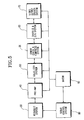
- a digital magnetic recorder/player includes a mechanical system 30 having a plurality of mechanical devices such as a motor for driving a cassette of magnetic tape 10 and a drum motor for driving the head drum 20, a servo control system 80 for position and speed control of the mechanical system 30, a pre-amp 40 for amplifying the signal to be recorded onto the magnetic tape 10 or for amplifying the signal that has been reproduced from the magnetic tape 10, an equalizer system 50 for equalizing a signal to be recorded onto the magnetic tape 10 or for equalizing a signal that has been reproduced from the magnetic tape 10, an error checking and compression system 55 for performing error check and data compression during the signal recording/reproducing operation, a shuffling and digital-to-analogue (D/A) system 60 for shuffling the data of the signal to be recorded onto the magnetic tape 10 or for shuffling the data of the signal that has been reproduced from the magnetic tape 10 and converting digital data to analogue data, a video output driver system 70 for producing sound signals through proper devices such as
- the pre-amp 40 includes three recording/reproducing amplifiers 41, 42, 43 for amplifying signals to be recorded onto the magnetic tape 10 and for amplifying signals that have been reproduced from the magnetic tape 10 during recording/reproducing by heads A, B, C, and pre-amp control logic 45 for controlling the recording/reproducing amplifiers 41, 42, 43.
- the pre-amp 40 amplifies the signal to be recorded on the magnetic tape 10 and transmits the amplified signal to heads A and B.
- the pre-amp 40 also amplifies the signal reproduced by head C and transmits the amplified signal to the microcomputer 90.
- the pre-amp control logic 45 controls the respective recording/reproducing amplifiers 41, 42, 43 so that the head C can perform reproduction while heads A and B perform recording.
- pre-amp control logic 45 includes a first switch 100 and a second switch 102.
- the microcomputer 90 outputs switching pulses to pre-amp control logic 45.
- the switching pulses are shown in Figure 7.
- the switching pulses can also be referred to as switching signals.
- head A When the first switch 100 is closed in response to the switching pulse, head A will record the input signal.
- head B When the first switch 100 is open in response to the switching pulse, head B will record the input signal.
- the second switch 102 is closed in response to the switching, the head C will reproduce the recorded signal.
- the operation of the switches can be modified so that switch 100 is open in response to the switching pulse to cause head A to record the input signal, for example. Different terms can be used to describe the operating of the switches, of course.
- the switches can be opened/closed, activated/deactivated, turned on/turned off, for example.
- Figure 7 is a graph showing the switching timing of the respective heads A, B, and C which are controlled by the pre-amp control logic 45. As shown in Figure 7, in a region where the switching pulse for heads A and B is high, head A performs recording operation, while in a region where the switching pulse is low, head B performs recording operation. In a region where the switching pulse for head C is high, head C performs reproduction, while in a region where the switching pulse is low, head C stops reproducing.
- the switching pulse for the heads A and B is switched to high or low in every 180° rotation of the head drum 20. Accordingly, during the rotation of the head drum 20, heads A and B are activated alternately, and sequentially record a signal in the second and first slanting tracks 12, 11 of the magnetic tape 10.
- the switching pulse for head C is switched to high after a predetermined time from the beginning of the low pulse region of the switching pulse for heads A and B.
- the predetermined time corresponds to a 90° rotation of the head drum 20.
- the switching pulse for head C is switched to high and low in every 180° rotation of the head drum 20.
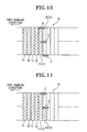
- Figures 8 to 11 show the variation of the position of the heads A, B, C on the magnetic tape 10 when the heads A, B, C are controlled as described above with reference to Figure 7.
- Figures 8 to 11 are similar to Figures 3 and 4 in that Figures 8 to 11 also show the first and second slanting tracks 11, 12 perpendicular with respect to the running direction of the magnetic tape 10 for an easier understanding.
- Figures 8 to 11 identify the first slanting track 11 with reference numeral 11(1), and identify the second slanting track 12 with reference numeral 12(2).
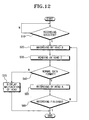
- FIG. 12 A method of detecting recorded signal abnormalities is illustrated by Figure 12.
- the inventive recording process is started by the digital magnetic recorder/player when the recording process is selected.
- the inventive recording process is the process for detecting the abnormality of recorded signal during recording.
- the head drum 20 is rotated, and head B is positioned at the end of the first slanting track 11(1).
- This configuration is shown in Figure 8.
- the switching pulse of heads A and B is switched to low, and the pre-amp control logic 45 activates head B recording/reproducing amplifier 42, activating the recording operation of head B.
- the switching pulse is shown in Figure 7.
- the switching pulse can also be referred to as a switching signal.
- the pre-amp control logic 45 and the amplifier 42 are shown in Figure 6.
- the input signal to be recorded is input to pre-amp 40, the input signal is amplified by the pre-amp 42, and recorded on the first slanting track 11(1) by head B.
- the recording operation is maintained until head B reaches the upper end of the first slanting track 11(1).
- the input signal to be recorded by heads A and B is shown to be inputted to pre-amp 40 in Figure 6.
- the input signal includes the information that is to be recorded onto the tape 10. That input signal can contain one or more of the following: video information, audio information, text data, formatting data, control data, numeric data, reference data, encryption data, auxiliary data, encoded data, other data.
- step S30 when head B reaches the middle of the first slanting track 11 (1) during the recording operation of head B, head C reaches the lower end of the first track 11 (1).
- This configuration is shown in Figure 9.
- the pre-amp control logic 45 starts reproducing operation of the head C by driving the head C recording/reproducing amplifier 43. Since the width of the respective heads A, B, and C is wider than the width of the respective first and second tracks 11(1) and 12(2), the signal is recorded on the first slanting track 11 (1) and partially on the second slanting track 12(2) next to the first slanting track 11(1). Head C reproduces the signal recorded in the first slanting track 11(1) and the second slanting track 12(2).
- the pre-amp control logic 45 stops the recording by head B and begins recording the signal on the second slanting track 12(2) by driving the head A recording/reproducing amplifier 41. In other words, the pre-amp control logic 45 stops the recording operation performed by head B and starts a recording operation by head A.
- head C reaches the upper end of the first slanting track 11 (1), and the head A is positioned at the middle of the second slanting track 12(2).
- This configuration is shown in Figure 11.
- the pre-amp control logic 45 stops the reproducing operation of head C.
- the recording operation of head A is maintained until head A reaches the upper end of the second slanting track 12(2).
- head A When head A reaches the upper end of the second slanting track 12(2), head B reaches the lower end of the first slanting track 11 next to the second slanting track 12(2), and head B re-starts recording operation.
- the recording operation is continuously performed by heads A and B, while head C reproduces the signal recorded by head B after a predetermined time period.
- the signal reproduced by head C is input into the microcomputer 90 through the pre-amp 43.
- the microcomputer 90 determines whether the recording is being normally performed or not. Determining recorded signal abnormality of the recorder/player by using the signal reproduced by head C can be performed in many ways. For illustrative purposes, described below are some methods of determining abnormality of recorded signals.
- the microcomputer 90 can use a comparator function to compare the signals in order to detect abnormalities.
- step S40 can correspond to a comparison of data. That is, in step S40, a reference signal can be compared to the signal reproduced by head C. If the reference signal and the signal from head C are substantially equal, then it is deemed that no abnormalities are present, and thus the user is not notified that errors have occurred. However, if the reference signal and the signal from head C are not substantially equal, then it is deemed that abnormalities are present, and thus the user is notified that errors have occurred.
- step S40 when the microcomputer 90 determines the recording is being normally performed by head B, then step S50 is performed next.
- head A performs recording.
- step S60 a determination is made as to whether recording is finished. Until recording is finished, the recording, the reproducing, and the recorded signal abnormality detection are continuously performed (steps S20 to S40).
- step S40 if the microcomputer 90 determines that a recorded signal abnormality exists in the signal recorded by the head B, then step S70 is performed next.
- the microcomputer 90 indicates the abnormal status on a display (not shown) of the digital magnetic recorder/player. Accordingly, the user is notified of the abnormality of the signal, and accordingly deals with the problem, for instance by stopping the recording, having the apparatus repaired, eliminating the foreign matter from the head, or the like.
- the user can be notified of the abnormality by a sound such as an audio alarm, by a light, by information displayed on a display including text and/or images, or the user can be notified by any combination of sound, light, and information.
- the microcomputer 90 can detect an abnormality in a recorded signal of the recorder/player using many different methods.
- One method that microcomputer 90 can use, for example, to determine that a recorded signal is abnormal, is to compare the data format of the data reproduced from the tape 10 with a predetermined data format.
- data can be stored in the respective sectors 11a to 11d of the first slanting track 11(1), in accordance with a predetermined data format, and the microcomputer 90 can be provided with information about the predetermined data format.
- the microcomputer 90 can receive the data format which is reproduced using head C, and then compare that received data format with the predetermined data format.
- the predetermined data format information can be any one of many different types of information.
- the predetermined data format information can be one or more types of information.
- the predetermined data format can correspond to a synchronization information, identification (ID) information, date-related information, time-related information, index-related information, structure-related information, or another type of information.
- the predetermined data format can correspond to any predetermined information.
- head C reproduces a recorded signal from tape 10.
- the reproduced signal is then conveyed from head C to the error checking and compression system 55 for processing and then to microcomputer 90.
- the processing performed by error checking and compression system 55 is shown in more detail in Figure 15.
- the data reproduced by head C can be conveyed to other units, in addition to units 55 and 90, but Figure 14 has simplified the process for illustrative purposes.
- the signal reproduced by head C is conveyed to unit 55 for processing and then to microcomputer 90.
- the microcomputer 90 also receives predetermined data format information stored in memory 104.
- the memory 104 can be an internal memory of microcomputer 90 or an external memory.
- the memory 104 is either contained within microcomputer 90 or is connected to microcomputer 90.
- the microcomputer compares the data from unit 55 with the data stored in the memory 104. If a number of differences exceeding a preset threshold is detected, then the microcomputer 90 determines that abnormalities exist and outputs a signal indicating that abnormalities exist to notify a user. If a particular type of differences is detected, then the microcomputer 90 determines that abnormalities exist and outputs an appropriate signal to notify a user.
- FIG. 14 One example of the process shown in Figure 14 is as follows. It is assumed that a family is making a home movie for their relatives. The home movie is being made on 10 January 2001. If the predetermined data format includes date information, then the memory 104 of the inventive apparatus stores the current date which is 10 January 2001. The family begins to videotape a picnic, and head B records the data onto tape 10. Head B records the current date and time onto the tape 10, in addition to the video images of the family having a picnic. Very soon after tape B records the data onto the tape 10, head C reproduces that recorded information and conveys that information to the microcomputer 90. The microcomputer 90 compares the predetermined data received from the memory 104 with the reproduced information received from unit 55. The memory 104 has stored the current date 10 January 2001.
- the date in the reproduced information will be the same as the date stored in the memory 104. Thus, the user will not be notified that there are abnormalities. However, if the reproduced information contains a date that is not 10 January 2001, or does not contain any date, or contains corrupted or invalid information, then an abnormality is detected, and the user will be promptly notified that the abnormality is present.
- the notification to the user could be in the form of one or more of the following: a beep or other sound, a flashing or constant light, an image or a text message being displayed, a vibration of the apparatus, or by some other means whereby the user is alerted to the fact that an abnormality exists.
- the abnormality may exist for many different reasons.
- the abnormality may be caused by dirt on the head B, for example. Or the abnormality could be the result of a poorly manufactured tape 10, or an excessively used tape 10, or a tape 10 that has been exposed to very high temperatures, or by dirt on the tape 10. Presuming a user is attempting to record onto a tape that is damaged because the tape has been previously exposed to very high temperatures, this is what might happen: first, the user puts the damaged tape into the apparatus and begins to tape the family picnic. The user is immediately notified that an abnormality exists, because the data in memory 104 does not match the data in the reproduced signal. The user is now aware that a problem exists. The user throws away the damaged tape and puts a brand new tape in the apparatus, and begins recording the picnic again. Now the data in memory 104 matches the data in the reproduced signal, and there are no abnormalities.
- an embodiment of the present invention may promptly notify the user that abnormalities exist in the recording of the picnic. If the user was unfortunate enough to be using an apparatus that did not have the advantages of obtainable as a result of the present invention, the user might have spent the entire afternoon having a picnic with the family and taping the picnic. Then, later that day or later that week, the user would attempt to view the tape. Only then would the user realize that there were errors. The user might be frustrated and dissatisfied. The user had spent time and effort taping the picnic and had basically wasted a lot of time and effort. The user had expected to be able to send the tape to the relatives. But the abnormalities were so severe that the recording of the picnic was unintelligible. The relatives would be disappointed, because they were expecting to see the tape.
- An embodiment of the present invention allows the user to immediately be made aware of abnormalities in the recording.
- the user can try to use a different tape, or the user can use a different apparatus, or the user can use a cleaning device to clean the heads.
- the advantage of this embodiment of the present invention is that the user is promptly alerted to the fact that a problem exists. The user does not need to waste a lot of time and effort recording information, only to learn later that all that time and effort was utterly wasted.
- the present invention is efficient and sophisticated.
- no additional heads need to be added to the device. Heads A, B and C are already there.
- the preferred embodiment uses head C to detect errors in the standard definition (SD) mode. As was stated previously, heads A and B are used in SD mode, whereas head C is not needed.
- SD standard definition
- heads A and B are used in SD mode, whereas head C is not needed.
- the preferred embodiment efficiently and elegantly adds important and useful functions to a recording apparatus. No additional heads need to be added to utilize the preferred apparatus and method according to the present invention.
- the present invention is advantageous because the present invention does not stop recording in order to read the recorded signal.
- head B is able to constantly record the input signal
- head C is able to constantly reproduce the recorded signal.
- This is an efficient design.
- a less efficient design might need to stop recording the signal in order to reproduce the recorded signal.
- the present invention is advantageous over the aforementioned less efficient design.
- the useful life of an apparatus can be shortened by excessive starting and stopping. Additional control signals are needed for excessive starting and stopping. Battery life can be reduced due to excessive starting and stopping. Power consumption can increase in an undesirable way due to excessive starting and stopping.
- head C preferably reads data from the track that was most recently written to.
- head B records data to track 11(1) of tape 10 and then head C promptly reproduces that data from track 11(1). This allows the user to be promptly notified of abnormalities, and is also advantageous for reasons of efficiency and design.
- the predetermined data stored in memory 104 can be any one (or more) of many different types of information, as described above.
- the date is one example. Synchronizing data is another example. Other header-type information is another example. Standard reference data is another example. A combination of different types of information can be used for the predetermined data stored in memory 104.
- the number of bits of the data reproduced from the magnetic tape 10 will correspond to the number of bits of the data stored in the respective sectors 11a to 11d.
- the recorded signal abnormality detection can also be accomplished by using the fact that the sub-code sector 11a stores information about date and time. That is, the abnormality of recorded data can be detected either by determining whether the signal reproduced from the magnetic tape 10 contains information about the date and time, or by determining whether the insert and track information (ITI) sector 11d stores information about the tracks.
- ITI insert and track information
- Figure 13 is a flowchart illustrating a second method of detecting recorded signal abnormalities. Referring to Figure 13, the steps of selecting recording operation (S110), recording by head B (S120), reading by head C (S130), recording by head A (S150), determining whether recording is finished (S160), and displaying malfunction (S170) are similar to the corresponding steps described above in the description of the first embodiment, with reference to steps 10, 20, 30, 50, 60 and 70 of Figure 12.
- Step S40 in Figure 12 is not the same as step S140 in Figure 13.
- Step S140, comprising detecting abnormality of recorded signal, which is the unique feature of the second embodiment, will now be described below in greater detail.
- Step S140 of Figure 13 includes the substeps S141 and S142.
- the envelope of the signal reproduced by head C is generated.
- the voltage level of the envelope is compared with a reference voltage level. If the voltage level of the envelope is greater than or equal to the reference voltage level, then the microcomputer 90 determines that no abnormalities exist and then head A records data at step S150. Otherwise, step S170 is performed to alert a user to an abnormality in the recording operation.
- the signal reproduced by head C is input into the microcomputer 90 via the pre-amp 43.
- the microcomputer 90 generates the envelope of the signal reproduced by the head C (step S141).
- the envelope can be easily generated by proper methods such as a digital-to-analogue (D/A) conversion that converts digital signal reproduced by head C into analogue signal.
- D/A digital-to-analogue
- the microcomputer 90 determines whether there is a recorded signal abnormality (step S142). For example, when the voltage level of the envelope is greater than the reference voltage level, the microcomputer 90 determines that there is no recorded signal abnormality.
- the microcomputer 90 determines there is a recorded signal abnormality.
- a voltage level usually obtained from the signal normally recorded on the magnetic tape 10 by the head B can be tentatively set as a reference signal level.
- the unit 55 includes units 106, 108, 110, and 112.
- the units 106 and 108 are used.
- Unit 106 serves to perform processing for modulating, compressing and arranging the data to be recorded.
- Unit 108 serves to transmit the modulated, compressed, and arranged data to the equalizer 50.
- the equalizer 50 will equalize the data and then transmit the equalized data to the pre-amp 40 for amplification. Then the data will be transmitted to the heads so that the data can be recorded onto the tape 10.
- Unit 110 serves to perform processing for demodulating, expanding, and rearranging the data to be reproduced.
- Unit 112 serves to transmit the demodulated, expanded, and rearranged data to the microcomputer 90. The microcomputer 90 will then perform the comparisons to detect abnormalities, as described above.
- data will be transmitted from unit 55 to unit 40 and then to unit 30 when the apparatus is in a write mode or recording mode.
- Data will be transmitted from unit 30 to unit 40 to unit 50 and then to unit 55 when the present invention is in a read mode or reproducing mode.
- the preferred embodiments of the present invention use head C, which is used in the long-play mode of the SDL type recorder/player, to detect the abnormality of the recorded signal. That is, in the digital magnetic recorder/player which can be operated both according to the SD type and SDL type, head C, which is not used especially according to the SD type apparatus, is used to detect the abnormality of the recorded signal. Accordingly, without having to employ an additional recording/reproducing head, the abnormality of the recorded signal can be detected by the head C which is installed in the general digital magnetic recorder/player.
- the method for detecting abnormality of the recorded signal according to the present invention still can be applied by adding a separate reproducing head.
- the preferred embodiments of the present invention show the case where only the abnormality of signal recorded by the head B is detected by reproducing signal recorded by the head B.
- the foreign matter which can be the main cause of the malfunction of the head, is attached on the heads when the heads are used or exposed in the air for a long period of time
- the presence of foreign substances on one head (head B) means the same situation at the other heads which have been used or exposed in the air for the same period of time as head A. Accordingly, the result obtained after detecting abnormality of the signal recorded by the head B can sufficiently show the abnormality of the recorded signal of the digital magnetic recorder/player.
- an abnormality of recorded signal which is caused due to the presence of the foreign substances or from other problem sources, can be detected either by A) reproducing the signal which is recorded on the magnetic tape 10 and checking the data format of the signal, or by B) comparing the voltage level of an envelope of recorded signals with a reference voltage level. Accordingly, the user has a convenience since she/he is notified of the abnormality of recorded signal while performing recording. Further, since a head for long play mode, which is not used in the standard mode, is used to detect the abnormality of the recorded signal, the abnormality detection can be easily performed without having to employ an additional recording head.
- the present invention can be applied to digital video cassette (DVC) units, other types of video recording units, audio recorders.
- DVC digital video cassette
- the present invention can be used in conjunction with media other than the digital magnetic tape 10 described above.
- other media such as the media used by computers, including a hard disk drive used by a computer and a removable medium used by a computer, and the like, can be used in conjunction with the principles of the present invention.
- the present invention can be applied to magnetic media such as magnetic tape, disks used in hard disk drives, disks used in other drives, and the like.
- the present invention can also be applied to optical media such as a factory pressed compact disk (CD), a compact disk-recordable (CD-R), a compact disk-rewriteable (CD-RW), laser disks, and other optical media.
- CD factory pressed compact disk
- CD-R compact disk-recordable
- CD-RW compact disk-rewriteable
- the detected abnormality in the recorded signal can be caused by a presence of contamination on a head, by a presence of foreign substances on a head, by a presence of contamination on a medium, by a poorly manufactured medium, by an excessively used medium, by an unstable power supply, or by other problem sources.
- a head C reads data that was written by head B, and then a determination is made as to whether there are abnormalities or irregularities or problems with the data written by head B.
- the use of head C to reproduce a recorded signal need not be limited to a standard definition (SD) mode.
- Head C can be used in modes different from the standard definition (SD) mode, in accordance with the principles of the present invention.
- heads A and C are used to record information on tape 10, while head B is unused.
- a particular track of tape 10 will be adjacent to head B before that particular track is adjacent to head C, in accordance with the direction of rotation of drum 20 and the direction of travel of tape 10 shown in Figure 1.
- SDL standard definition long play
- information previously recorded on the tape 10 can be read from the tape 10 using head B immediately prior to the head C writing new information onto the tape 10.
- the information read by head B can then be written to another medium or otherwise transmitted.
- the previously written information on tape 10 can be stored before it is overwritten by the information being written by head C.
- first information can be read from tape 10 (using head B) and then second information can be written to tape 10 (using heads A and C) all in one operation, without any need to stop rotation of the tape 10.
Landscapes
- Digital Magnetic Recording (AREA)
- Signal Processing For Digital Recording And Reproducing (AREA)
- Recording Or Reproducing By Magnetic Means (AREA)
- Adjustment Of The Magnetic Head Position Track Following On Tapes (AREA)
Claims (14)
- Tonbandgerät umfassend einen ersten Kopf (B) und einen zweiten Kopf (C), die so angeordnet sind, dass von dem ersten Kopf (B) auf einem Tonband (10) aufgenommene Daten im Wesentlichen unmittelbar vom zweiten Kopf (C) lesbar sind, und eine Kontrollvorrichtung (45, 90), die gestaltet ist, um einen abnormalen Aufnahmezustand in Abhängigkeit von der Ausgabe des zweiten Kopfes (C) während der Aufnahme zu bestimmen, dadurch gekennzeichnet, dass die Kontrollvorrichtung (45, 90) gestaltet ist, um ein vom zweiten Kopf (C) ausgegebenes Zeitsignal (11d, 12d) mit einem Zeitzeiger zu vergleichen, die mit den Daten zusammenhängt, welche dem ersten Kopf (B) zur Aufnahme zugeführt werden.
- Tonbandgerät nach Anspruch 1, wobei die Kontrollvorrichtung (45, 90) weiter gestaltet ist, um den Hüllkurvenpegel der Ausgabe des zweiten Kopfes (C) mit einem Referenzwert zu vergleichen.
- Tonbandgerät nach Anspruch 1 oder 2, wobei der erste und zweite Kopf (B, C) in einer Kopftrommel (20) angebracht sind, die gedreht wird, um schräge Spuren (11, 12) auf einem Tonband (10) zu bilden, auf welches aufgenommen wird.
- Tonbandgerät nach Anspruch 3, wobei der zweite Kopf (C) vom ersten Kopf (B) um einen Winkel von 90° um die Drehachse der Kopftrommel (20) beabstandet ist.
- Tonbandgerät nach Anspruch 3 oder 4, umfassend einen dritten Kopf (A), der zur Aufnahme von Daten auf den Spuren (11, 12) abwechselnd mit dem ersten Kopf (B) angeordnet ist.
- Tonbandgerät nach Anspruch 5, wobei der zweite Kopf (C) als Aufnahmekopf zusammen mit dem ersten und dritten Kopf (B, A) betreibbar ist, um in einem Longplay-Aufnahmemodus aufzunehmen.
- Tonbandgerät nach einem der vorangehenden Ansprüche, umfassend Mittel (60) zur Bereitstelldung eines digitalen Signals an den ersten Kopf (B) zur Aufnahme.
- Tonbandgerät nach einem der vorangehenden Ansprüche, wobei die Kontrollvorrichtung angeordnet ist, um ein erstes und zweites Schaltsignal auszugeben; wobei das Tonbandgerät weiter umfasst:einen ersten Schalter, der in Funktion des ersten Schaltsignals arbeitet, wobei die Betätigung des ersten Schalters den ersten Kopf (B) aktiviert, um erste Daten auf das Tonband aufzunehmen; undeinen zweiten Schalter, der in Funktion des zweiten Schaltsignals arbeitet, wobei die Betätigung des zweiten Schalters den zweiten Kopf (C) aktiviert; um die zweiten Daten vom Medium wiederzugeben, wobei die zweiten Daten den auf dem Medium aufgenommenen ersten Daten entsprechen;wobei das Wiedergeben der zweiten Daten während der Aufzeichnung der ersten Daten durchgeführt wird.
- Tonbandgerät nach Anspruch 8, weiter umfassend:einen Komparator, der vorbestimmte Referenzdaten mit den zweiten Daten vergleicht, und ein Alarmsignal ausgibt, um einen Benutzer zu benachrichtigen, wenn die vorbestimmten Referenzdaten nicht im Wesentlichen gleich den zweiten Daten sind.
- Tonbandgerät nach Anspruch 9, weiter den Komparator umfassend, der das Alarmsignal nicht ausgibt, wenn die vorbestimmten Referenzdaten im Wesentlichen gleich den zweiten Daten sind.
- Tonbandgerät nach Anspruch 9, weiter umfassend das Alarmsignal, um einen Benutzer zu benachrichtigen, wobei das Alarmsignal mindestens einem Signal entspricht, das aus einem hörbaren Geräusch, sichtbarem Licht, einer Textnachricht und einer Vibration, die vom Benutzer erfassbar sind, ausgewählt ist.
- Tonbandgerät nach Anspruch 8, weiter die von dem Medium wiedergegebenen zweiten Daten umfassend, wobei die zweiten Daten im Wesentlichen den auf das Medium aufgenommenen ersten Daten identisch sind, wenn keine Abnormalitäten vorhanden sind.
- Tonbandgerät nach einem der vorangehenden Ansprüche, wobei der Zeitanzeiger in einem Speicher (104) gespeichert ist und das Zeitanzeigesignal (11d, 12d) mit dem gespeicherten Zeitanzeiger verglichen wird.
- Verfahren zum Erfassen einer Abnormalität in aufgenommenen Daten, umfassend die folgenden Schritte:Aufnehmen von Daten auf ein Tonband (10) unter Verwendung eines ersten Kopfes (B);Wiedergabe der Daten vom Tonband (10) unter Verwendung eines zweiten Kopfes (C), während die Daten auf das Tonband (10) aufgenommen werden; undBestimmen eines abnormalen Aufnahmezustands in Abhängigkeit von der Ausgabe des zweiten Kopfes (C) während der Aufnahme, gekennzeichnet durch das Vergleichen einer Zeit und/oder eines Datums (11d, 12d) der Ausgabe des zweiten Kopfes (C) mit einer Zeit und/oder Datum der Daten, die dem ersten Kopf (B) zur Aufnahme zugeführt werden.
Priority Applications (1)
| Application Number | Priority Date | Filing Date | Title |
|---|---|---|---|
| EP05108883A EP1619668A3 (de) | 2001-02-22 | 2001-10-31 | Detektion einer abnormalen Aufzeichnung |
Applications Claiming Priority (2)
| Application Number | Priority Date | Filing Date | Title |
|---|---|---|---|
| US789822 | 2001-02-22 | ||
| US09/789,822 US6747828B2 (en) | 2001-02-22 | 2001-02-22 | Apparatus and method for detecting an abnormality in a recorded signal |
Related Child Applications (1)
| Application Number | Title | Priority Date | Filing Date |
|---|---|---|---|
| EP05108883A Division EP1619668A3 (de) | 2001-02-22 | 2001-10-31 | Detektion einer abnormalen Aufzeichnung |
Publications (3)
| Publication Number | Publication Date |
|---|---|
| EP1237151A2 EP1237151A2 (de) | 2002-09-04 |
| EP1237151A3 EP1237151A3 (de) | 2003-07-23 |
| EP1237151B1 true EP1237151B1 (de) | 2006-10-11 |
Family
ID=25148776
Family Applications (2)
| Application Number | Title | Priority Date | Filing Date |
|---|---|---|---|
| EP01309243A Expired - Lifetime EP1237151B1 (de) | 2001-02-22 | 2001-10-31 | Detektion einer abnormalen Aufzeichnung |
| EP05108883A Withdrawn EP1619668A3 (de) | 2001-02-22 | 2001-10-31 | Detektion einer abnormalen Aufzeichnung |
Family Applications After (1)
| Application Number | Title | Priority Date | Filing Date |
|---|---|---|---|
| EP05108883A Withdrawn EP1619668A3 (de) | 2001-02-22 | 2001-10-31 | Detektion einer abnormalen Aufzeichnung |
Country Status (4)
| Country | Link |
|---|---|
| US (2) | US6747828B2 (de) |
| EP (2) | EP1237151B1 (de) |
| KR (1) | KR100436755B1 (de) |
| DE (1) | DE60123744T2 (de) |
Families Citing this family (3)
| Publication number | Priority date | Publication date | Assignee | Title |
|---|---|---|---|---|
| US7006002B2 (en) * | 2004-03-08 | 2006-02-28 | Eton Corporation | Combination power failure light and FM/AM radio with a clock and alarm function |
| JP2007265546A (ja) * | 2006-03-29 | 2007-10-11 | Fujitsu Ltd | 磁気記録ヘッドのオフセット測定方法及び磁気記録再生装置 |
| US10809966B2 (en) * | 2013-03-14 | 2020-10-20 | Honeywell International Inc. | System and method of audio information display on video playback timeline |
Family Cites Families (30)
| Publication number | Priority date | Publication date | Assignee | Title |
|---|---|---|---|---|
| US3864736A (en) * | 1973-06-25 | 1975-02-04 | Burroughs Corp | Magnetic recording verification |
| JPS6120284A (ja) * | 1984-07-06 | 1986-01-29 | Matsushita Electric Ind Co Ltd | 磁気記録再生装置 |
| JPH0759071B2 (ja) * | 1986-06-26 | 1995-06-21 | ソニー株式会社 | 映像信号記録再生装置 |
| IT1213344B (it) | 1986-09-17 | 1989-12-20 | Honoywell Information Systems | Architettura di calcolatore a tolleranza di guasto. |
| JPH01296408A (ja) | 1988-05-23 | 1989-11-29 | Mitsubishi Electric Corp | 磁気テープ記録再生装置 |
| JP2764948B2 (ja) * | 1988-10-17 | 1998-06-11 | ソニー株式会社 | 記録確認装置 |
| JP2589168B2 (ja) * | 1988-12-17 | 1997-03-12 | アルプス電気株式会社 | 回転ヘッド式磁気記録再生装置 |
| KR910010182B1 (ko) * | 1988-12-31 | 1991-12-20 | 삼성전자 주식회사 | 다기능 제어 비디오헤드 선택방법 및 장치 |
| JPH02287904A (ja) * | 1989-04-27 | 1990-11-28 | Matsushita Electric Ind Co Ltd | 磁気記録再生装置 |
| JPH04344372A (ja) * | 1991-05-22 | 1992-11-30 | Hitachi Ltd | ディジタル信号記録再生装置 |
| JPH0581784A (ja) * | 1991-09-19 | 1993-04-02 | Canon Inc | 磁気記録再生装置 |
| JPH05314671A (ja) * | 1992-05-14 | 1993-11-26 | Sony Corp | 情報記録再生装置 |
| JPH0676552A (ja) | 1992-08-25 | 1994-03-18 | Sony Corp | 記録再生装置 |
| KR0170261B1 (ko) * | 1992-09-02 | 1999-04-15 | 김광호 | 최적 기록/재생장치 |
| JP3158743B2 (ja) * | 1992-11-11 | 2001-04-23 | ソニー株式会社 | 磁気テープ記録再生装置 |
| US5933567A (en) | 1993-01-13 | 1999-08-03 | Hitachi America, Ltd. | Method and apparatus for controlling the position of the heads of a digital video tape recorder during trick play operation and for recording digital data on a tape |
| US5479098A (en) * | 1993-03-15 | 1995-12-26 | Trace Mountain Products, Inc. | Loop-back circuit for testing a magnetic recording system with simultaneous read and write functions |
| JPH08221701A (ja) * | 1995-02-13 | 1996-08-30 | Hitachi Ltd | 記録再生装置及び記録再生方法 |
| JP3693380B2 (ja) * | 1995-04-20 | 2005-09-07 | 富士写真フイルム株式会社 | 磁気記録再生装置の異常検出方法 |
| JPH0973738A (ja) * | 1995-06-30 | 1997-03-18 | Sony Corp | 記録装置 |
| JP3572761B2 (ja) * | 1995-10-31 | 2004-10-06 | ミツミ電機株式会社 | 回転磁気ヘッドの検査方法 |
| JPH09153207A (ja) * | 1995-11-29 | 1997-06-10 | Sanyo Electric Co Ltd | 磁気記録再生装置 |
| EP0794531B1 (de) | 1996-03-04 | 2002-06-05 | Hitachi, Ltd. | Gerät zur Aufnahme/Wiedergabe von digitalen Signalen |
| JPH09245349A (ja) * | 1996-03-08 | 1997-09-19 | Hitachi Ltd | 磁気記録再生装置 |
| JPH1031807A (ja) | 1996-07-17 | 1998-02-03 | Toshiba Corp | リードアフターライト回路及び磁気記録再生装置 |
| JPH10143812A (ja) * | 1996-11-01 | 1998-05-29 | Sharp Corp | 磁気記録再生装置 |
| US6031679A (en) * | 1996-11-27 | 2000-02-29 | Victor Company Of Japan, Ltd. | Magnetic recording/reproducing apparatus capable of reproducing digital data at minimum error rate |
| US6163421A (en) | 1997-09-05 | 2000-12-19 | Sony Corporation | Azimuth magnetic recording and reproducing apparatus and method employing waveform equalization |
| DE69832450T2 (de) * | 1997-09-26 | 2006-08-03 | Matsushita Electric Industrial Co., Ltd., Kadoma | Magnetisches Aufnahme- und Wiedergabegerät |
| JP3647708B2 (ja) * | 2000-02-09 | 2005-05-18 | ヒタチグローバルストレージテクノロジーズネザーランドビーブイ | 磁気ヘッド浮上量異常検出方法、データ書込方法およびハード・ディスク・ドライブ装置 |
-
2001
- 2001-02-22 US US09/789,822 patent/US6747828B2/en not_active Expired - Fee Related
- 2001-05-03 KR KR10-2001-0024149A patent/KR100436755B1/ko not_active Expired - Fee Related
- 2001-10-31 DE DE60123744T patent/DE60123744T2/de not_active Expired - Fee Related
- 2001-10-31 EP EP01309243A patent/EP1237151B1/de not_active Expired - Lifetime
- 2001-10-31 EP EP05108883A patent/EP1619668A3/de not_active Withdrawn
-
2004
- 2004-04-02 US US10/815,665 patent/US7031088B2/en not_active Expired - Fee Related
Also Published As
| Publication number | Publication date |
|---|---|
| US20040184179A1 (en) | 2004-09-23 |
| EP1237151A3 (de) | 2003-07-23 |
| US6747828B2 (en) | 2004-06-08 |
| KR20020068946A (ko) | 2002-08-28 |
| DE60123744D1 (de) | 2006-11-23 |
| EP1619668A2 (de) | 2006-01-25 |
| DE60123744T2 (de) | 2007-08-23 |
| EP1619668A3 (de) | 2007-02-21 |
| US20020114094A1 (en) | 2002-08-22 |
| EP1237151A2 (de) | 2002-09-04 |
| US7031088B2 (en) | 2006-04-18 |
| KR100436755B1 (ko) | 2004-06-23 |
Similar Documents
| Publication | Publication Date | Title |
|---|---|---|
| JP3459216B2 (ja) | 光ディスク装置 | |
| JP3049919B2 (ja) | データ再生装置 | |
| EP1237151B1 (de) | Detektion einer abnormalen Aufzeichnung | |
| JP4604892B2 (ja) | 情報記録/再生装置 | |
| JP4692117B2 (ja) | 情報記録/再生装置 | |
| US7242642B2 (en) | High speed recording and reproducing for optical disk device of different format | |
| JPH06325473A (ja) | 記録再生装置 | |
| KR20040012642A (ko) | 기록된 신호의 이상을 검출하는 장치 및 방법 | |
| JPS6276083A (ja) | 再生信号記録装置 | |
| KR20030067638A (ko) | 기록된 신호의 이상을 검출하는 장치 및 방법 | |
| JP4497197B2 (ja) | 映像記録装置 | |
| JPH1066022A (ja) | ディジタル記録再生装置 | |
| US20060204212A1 (en) | Information recording/reproducing device | |
| JP4053964B2 (ja) | ディスク記録装置とディスク再生装置 | |
| EP1672639B1 (de) | Informationsaufzeichnungs-/wiedergabeeinrichtung | |
| JP3615106B2 (ja) | 再生装置 | |
| JP3037066B2 (ja) | ディスク再生装置 | |
| JP2006196091A (ja) | 映像音声信号記録再生装置 | |
| JP2001266545A (ja) | ディスク記録再生装置 | |
| JP2006024338A (ja) | 録画再生システム及びダビング方法 | |
| KR20040010977A (ko) | 광기록재생기의 연속기록 방법 및 장치 | |
| JP2001118298A (ja) | 記録/再生装置及び記録/再生方法 | |
| JPH04313876A (ja) | 情報再生装置 | |
| JPH01178177A (ja) | 画像記録再生装置 | |
| JP2005346782A (ja) | ディスク再生装置 |
Legal Events
| Date | Code | Title | Description |
|---|---|---|---|
| PUAI | Public reference made under article 153(3) epc to a published international application that has entered the european phase |
Free format text: ORIGINAL CODE: 0009012 |
|
| AK | Designated contracting states |
Kind code of ref document: A2 Designated state(s): AT BE CH CY DE DK ES FI FR GB GR IE IT LI LU MC NL PT SE TR |
|
| AX | Request for extension of the european patent |
Free format text: AL;LT;LV;MK;RO;SI |
|
| RIC1 | Information provided on ipc code assigned before grant |
Ipc: 7G 11B 27/36 B Ipc: 7G 11B 5/53 A Ipc: 7G 11B 21/18 B |
|
| PUAL | Search report despatched |
Free format text: ORIGINAL CODE: 0009013 |
|
| AK | Designated contracting states |
Designated state(s): AT BE CH CY DE DK ES FI FR GB GR IE IT LI LU MC NL PT SE TR |
|
| AX | Request for extension of the european patent |
Extension state: AL LT LV MK RO SI |
|
| 17P | Request for examination filed |
Effective date: 20030823 |
|
| AKX | Designation fees paid |
Designated state(s): DE FR GB IT |
|
| RAP1 | Party data changed (applicant data changed or rights of an application transferred) |
Owner name: SAMSUNG ELECTRONICS CO., LTD. |
|
| 17Q | First examination report despatched |
Effective date: 20050314 |
|
| GRAP | Despatch of communication of intention to grant a patent |
Free format text: ORIGINAL CODE: EPIDOSNIGR1 |
|
| GRAS | Grant fee paid |
Free format text: ORIGINAL CODE: EPIDOSNIGR3 |
|
| GRAA | (expected) grant |
Free format text: ORIGINAL CODE: 0009210 |
|
| AK | Designated contracting states |
Kind code of ref document: B1 Designated state(s): DE FR GB IT |
|
| PG25 | Lapsed in a contracting state [announced via postgrant information from national office to epo] |
Ref country code: IT Free format text: LAPSE BECAUSE OF FAILURE TO SUBMIT A TRANSLATION OF THE DESCRIPTION OR TO PAY THE FEE WITHIN THE PRESCRIBED TIME-LIMIT;WARNING: LAPSES OF ITALIAN PATENTS WITH EFFECTIVE DATE BEFORE 2007 MAY HAVE OCCURRED AT ANY TIME BEFORE 2007. THE CORRECT EFFECTIVE DATE MAY BE DIFFERENT FROM THE ONE RECORDED. Effective date: 20061011 |
|
| REG | Reference to a national code |
Ref country code: GB Ref legal event code: FG4D |
|
| REF | Corresponds to: |
Ref document number: 60123744 Country of ref document: DE Date of ref document: 20061123 Kind code of ref document: P |
|
| ET | Fr: translation filed | ||
| PLBE | No opposition filed within time limit |
Free format text: ORIGINAL CODE: 0009261 |
|
| STAA | Information on the status of an ep patent application or granted ep patent |
Free format text: STATUS: NO OPPOSITION FILED WITHIN TIME LIMIT |
|
| 26N | No opposition filed |
Effective date: 20070712 |
|
| PGFP | Annual fee paid to national office [announced via postgrant information from national office to epo] |
Ref country code: DE Payment date: 20081027 Year of fee payment: 8 |
|
| PGFP | Annual fee paid to national office [announced via postgrant information from national office to epo] |
Ref country code: FR Payment date: 20081014 Year of fee payment: 8 |
|
| PGFP | Annual fee paid to national office [announced via postgrant information from national office to epo] |
Ref country code: GB Payment date: 20081029 Year of fee payment: 8 |
|
| PG25 | Lapsed in a contracting state [announced via postgrant information from national office to epo] |
Ref country code: IT Free format text: LAPSE BECAUSE OF NON-PAYMENT OF DUE FEES Effective date: 20081031 |
|
| REG | Reference to a national code |
Ref country code: FR Ref legal event code: ST Effective date: 20100630 |
|
| PG25 | Lapsed in a contracting state [announced via postgrant information from national office to epo] |
Ref country code: DE Free format text: LAPSE BECAUSE OF NON-PAYMENT OF DUE FEES Effective date: 20100501 Ref country code: FR Free format text: LAPSE BECAUSE OF NON-PAYMENT OF DUE FEES Effective date: 20091102 |
|
| PG25 | Lapsed in a contracting state [announced via postgrant information from national office to epo] |
Ref country code: GB Free format text: LAPSE BECAUSE OF NON-PAYMENT OF DUE FEES Effective date: 20091031 |
|
| PGFP | Annual fee paid to national office [announced via postgrant information from national office to epo] |
Ref country code: IT Payment date: 20080208 Year of fee payment: 8 |
|
| PGRI | Patent reinstated in contracting state [announced from national office to epo] |
Ref country code: IT Effective date: 20110616 |
|
| PGRI | Patent reinstated in contracting state [announced from national office to epo] |
Ref country code: IT Effective date: 20110616 |