EP1205366B1 - A hood hinge and body structure - Google Patents
A hood hinge and body structure Download PDFInfo
- Publication number
- EP1205366B1 EP1205366B1 EP01126448A EP01126448A EP1205366B1 EP 1205366 B1 EP1205366 B1 EP 1205366B1 EP 01126448 A EP01126448 A EP 01126448A EP 01126448 A EP01126448 A EP 01126448A EP 1205366 B1 EP1205366 B1 EP 1205366B1
- Authority
- EP
- European Patent Office
- Prior art keywords
- hinge
- hood
- shock
- fixing
- set forth
- Prior art date
- Legal status (The legal status is an assumption and is not a legal conclusion. Google has not performed a legal analysis and makes no representation as to the accuracy of the status listed.)
- Expired - Lifetime
Links
Images


Classifications
-
- B—PERFORMING OPERATIONS; TRANSPORTING
- B60—VEHICLES IN GENERAL
- B60R—VEHICLES, VEHICLE FITTINGS, OR VEHICLE PARTS, NOT OTHERWISE PROVIDED FOR
- B60R21/00—Arrangements or fittings on vehicles for protecting or preventing injuries to occupants or pedestrians in case of accidents or other traffic risks
- B60R21/34—Protecting non-occupants of a vehicle, e.g. pedestrians
- B60R21/38—Protecting non-occupants of a vehicle, e.g. pedestrians using means for lifting bonnets
-
- B—PERFORMING OPERATIONS; TRANSPORTING
- B60—VEHICLES IN GENERAL
- B60R—VEHICLES, VEHICLE FITTINGS, OR VEHICLE PARTS, NOT OTHERWISE PROVIDED FOR
- B60R21/00—Arrangements or fittings on vehicles for protecting or preventing injuries to occupants or pedestrians in case of accidents or other traffic risks
- B60R21/34—Protecting non-occupants of a vehicle, e.g. pedestrians
- B60R2021/343—Protecting non-occupants of a vehicle, e.g. pedestrians using deformable body panel, bodywork or components
Definitions
- the present invention relates to a hood hinge structure of a vehicle for connecting together a hinge lower which fixed to a vehicle body and a hinge upper which fixed to a hood, and a body structure of a vehicle.
- a hood hinge structure comprising hinges connecting a hinge lower fixed to a vehicle body with a hinge upper fixed to a hood
- various kinds of structures For example, a first conventional structure shown in Fig. 8A-8C is an ordinary hood hinge structure.
- a hinge lower 24 is fixed to a vehicle body (frame upper) 22 extending longitudinally in the right and left side of an engine room, whereas a hinge upper 23 is fixed to a hood inner 21A of a hood (bonnet) 21.
- hinge lower 24 and hinge upper 23 are connected together at a hinge axial center H, while the hood 21 can be opened and closed about the hinge axial center H.
- reference character 32 designates a front pillar.
- Reference character 33 designates a front bulkhead.
- Reference character 34 designates a suspension upper bracket.
- Reference character 36 designates a frame side upper.
- Reference character 38 designates a wheel apron lower.
- Reference character 26 designates a fender panel.
- FIG. 9 a structure in JP-A-10-258773.
- an L-shaped support bracket 117 which is held by a fixing bracket 121, is fixed on the upper surface of an upper frame 112 in such a manner that it can drop down.
- a second hanging portion 128 of a hinge bracket 124 fixed to a hood panel 127 is rotatably connected to a first hanging portion 119 of the support bracket 117.
- a third conventional structure there is known a structure disclosed in JP-A-9-315266.
- the control unit when a control unit detects a collision with a pedestrian, the control unit actuates hood-lift-hold means so that a hood is lifted a predetermined amount by an inflator and a rod. Then, the hood is held at the thus lifted position, thereby securing a sufficient deformation stroke with respect to a shock given from the pedestrian.
- a clearance between the hinge lower 24 fixed to the upper surface of the frame upper 22 and the hinge upper 23 fixed to the hood inner 21A is narrow, which makes it difficult to mount the hinge lower 24 and hinge upper 23.
- a shock as shown by an arrow P is given to the hood hinge portion due to a collision with a pedestrian, there is a fear that the hinge lower 24 and hinge upper 23 can be butted against each other in a comparatively early stage. Therefore the shock cannot be absorbed sufficiently, thereby increasing damage to the pedestrian.
- Document JP-A-11-291948 discloses a hood hinge according to the preamble of claim 1.
- the third conventional structure in the normal running of the vehicle, since the hood surface is formed low, there is no fear that the aerodynamic characteristic can be lowered and the front field of vision can be narrowed.
- the present invention aims at solving the problems found in the above-mentioned conventional hood hinge structure and body structure for a vehicle. Accordingly, it is an object of the invention to provide a hood hinge and body structure for a vehicle, which not only can secure a sufficient shock-absorbing stroke in a hinge portion with a hood surface maintained low but also can enhance the efficiency of the hinge components mounting operation.
- a hood hinge and body structure comprising a body having a stepped portion that is located at a position lower than an upper surface of a frame upper of said body and at an engine room side, a hinge lower fixed to a hinge lower fixing portion that is located adjacent to the stepped portion and a hinge upper fixed to a hinge upper fixing portion of a hood and pivotably connected to the hinge lower to form a hinge at a connecting position, wherein the hinge upper fixing portion is opposed to the stepped portion in a vertical direction of the body.
- the invention further comprises a wave portion disposed on a side edge portion of the hood and at least in a vicinity of the hinge upper and being stretchable when an impact acts on the hood.
- the invention further comprises a shock-absorbing member interposed between the hinge upper fixing portion and the stepped portion.
- the shock-absorbing member is integrally formed with the hinge lower.
- the invention in a vehicle hood hinge structure as set forth in any one of the first to fourth aspects of the invention, the invention further comprising a fragile portion formed on the hinge lower between the hinge lower fixing portion and the connecting position.
- the stepped portion is located at a range between a strut tower of the body and a bulkhead of the body in a back-and-forth direction of the body and the stepped portion is situated lower than the top surface of a frame upper of the body.
- an upper surface portion of the strut tower is formed lower than the top surface.
- the invention in a vehicle body structure as set forth in the sixth or seventh aspect of the invention, the invention further comprising an overlapping flange overlapped with both of a front pillar of the body and the strut tower, and mounted on the body.
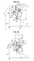
- Figs. 1A to 3C show a first embodiment of the hood hinge and body structure for the vehicle according to the invention.
- Fig. 1A is a section view of the main portions of the first embodiment.
- Fig. 1B is a view of the deforming state of the first embodiment when a shock is absorbed.
- Fig. 2A is a perspective view of the main portions of the first embodiment with the hood side thereof omitted.
- Fig. 2B is a perspective view of the front portion of a vehicle.
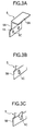
- Fig. 3A-3C are perspective views of modifications of a shock-absorbing member.
- the present invention is characterized in that, as shown in Fig.
- a hood hinge structure comprises a hinge lower 4 fixed to a vehicle body (frame upper) 2 and a hinge upper 3 fixed to a hood 1, that are connected together by hinge means.
- the engine room side of the vehicle body 2 serving as a hinge lower fixing portion is formed as a stepped portion 2A which is situated on a lower side.
- a hinge upper fixing portion (the hinge surface 3A of the hinge upper 3) such that it is opposed to the stepped portion 2A.
- a hood hinge portion is disposed in a portion designated by reference character D shown in Fig. 2B which is a perspective view of the front portion of a vehicle.
- a bonnet 1 is structured such that the rear end portion thereof is used as a hinge portion and thus the opening end portion of the front portion thereof can be opened and closed.
- the bonnet 1 can also be structured such that the front end portion thereof is used as a hinge portion and thus the opening end portion of the rear portion thereof can be opened and closed.
- the frame upper 2 which extends in the back-and-forth direction of the vehicle body and forms the hinge lower fixing portion, and a front bulkhead 13 extending in the width direction of the vehicle body, are fixedly secured to a frame side upper 16 with a fender panel 6 mounted to the outer-most side thereof.
- the fixing surface 4B of the L-shaped hinge lower 4 by a fixing bolt 8 is fixed to the upper surface of the frame upper 2, in fact, to the fixing surface 2B of the frame upper 2.
- the stepped portion 2A that is situated on the lower side is formed.
- the fixing surface 5B of such an L-shaped hinge catcher 5 as shown in Fig. 3A serving as a shock-absorbing member is fixed to the stepped portion 2A by a fixing bolt 11, thereby being able to absorb a shock given by the load that is applied from above.
- a hinge upper fixing portion is formed in the inner panel of the bonnet (hood 1), and the fixing surface 3B of the L-shaped hinge upper 3 is fixed to the hinge upper fixing portion by a fixing bolt 7.
- the hinge surface 3A of the hinge upper 3 is connected to the hinge surface 4A of the hinge lower 4 which is disposed so as to be opposed to the hinge surface 3A, at the hinge axial center H by hinge means.
- the butting surface 5A of the hinge catcher 5 disposed on the stepped portion 2A is situated adjacent to the hinge upper fixing surface 3B forming the hinge upper fixing portion.
- At least the outside of the hinge upper fixing portion of the side edge portion of the hood is formed as a bending promoting shape portion (wave portion) 1A, whereby the hood 1 can be deformed correspondingly to the shape of a pedestrian, which is applied to the vicinity of the hood hinge portion as an impact object.
- a fragile portion 9 which is formed of, for example, a bent portion.
- a fragile portion 10 which is formed of, for example, a bent portion.
- Fig. 3A-3C as the shock-absorbing function of the hinge catcher 5, there may be used mounting bolt holes 5C formed in the fixing surface 5B (which is to be mounted to the side surface of the stepped portion 2A) of the hinge catcher 5.
- the mounting bolt holes 5C there can be employed such a potbellied hole having a shock-absorbing function as shown in Fig. 3B.
- a bolt hole with a slit having a shock-absorbing function as shown in Fig. 3C.
- Fig. 2A is a perspective view of the main portions, which form the hinge portion of the first embodiment of the invention. Fig. 2A is drawn in such a manner that the hood side thereof is omitted.
- Fig. 2A is a perspective view of the main portions, which form the hinge portion of the first embodiment of the invention. Fig. 2A is drawn in such a manner that the hood side thereof is omitted.
- reference character 12 designates a front pillar
- reference character 14 stands for a suspension upper bracket forming the upper surface portion of a strut tower disposed in the suspension of the vehicle.
- the upper surface of the suspension upper bracket 14 is structured so as to be lower than the normal surface of the vehicle body (frame upper) 2 (that is, so as to be substantially flush with the stepped portion 2A).
- a hood hinge portion according to the present embodiment is structured in the above-mentioned manner, as shown in Fig. 1B.
- the hinge portion In the case that the head P of the pedestrian is butted against the hood 1 in the vicinity of the hinge portion due to a collision, the hinge portion is deformed within a relatively long shock-absorbing stroke L that is formed between the hinge upper 3 and stepped portion 2A of the frame upper 2, so as to be able to absorb the shock sufficiently, which makes it possible to minimize damage to the pedestrian.
- the side edge portion of the hood 1 is deformed correspondingly to the shape of the head portion P of the pedestrian as an impact object due to the existence of the bending promoting shape 1A formed of a wave portion.
- the hinge lower 4 can be deformed while absorbing the shock effectively. Then, the hinge upper fixing surface 3B and fixing bolt 7 can be butted against a butting surface 5A of a hinge catcher 5, which is a shock-absorbing member, to thereby effectively deform the hinge catcher 5 including a fragile portion 10 formed in the intermediate portion thereof, so that the shock can be absorbed.
- the stepped portion 2A since a stepped portion 2A is formed on the engine room side, and the shock-absorbing member is disposed on the stepped portion 2A, which functions as a shock-absorbing portion, the stepped portion 2A not only can facilitate the mounting operation of the hinge member but also has a further shock-absorbing function to absorb the shock that is given by the deformed hinge portion when it drops down into the engine room.
- the fragile portion 9 formed in the hinge surface 4A of the hinge lower 4 is curved on the engine room side, not only the vertical length of the hinge surface 4A is reduced and a space for mounting the fixing bolt 7 is increased to be able to enhance the efficiency of the fixing bolt mounting operation, but also such formation of the fragile portion 9 can promote the dropping and deformation of the hinge portion into the engine room to be able to contribute toward expanding the shock-absorbing stroke further.
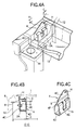
- Figs. 4A-4C and Figs. 5A-5B respectively show a second embodiment of a vehicle hood hinge structure and a vehicle body structure according to the invention.
- Fig. 4A is a perspective view of the main portions of the second embodiment with its hood side omitted.
- Fig. 4B is a section view of the main portions of the second embodiment.
- Fig. 4C is a perspective view of a shock-absorbing member.
- Fig. 5A and 5B are perspective views of modification of the above shock-absorbing member.
- the second embodiment is characterized in that, as shown in Fig. 4A-4C, the shock-absorbing member (in the case of the previously described first embodiment, the hinge catcher 5) is formed integral with a hinge lower 4.
- the hinge lower 4 which is disposed along the side wall to the bottom wall of a stepped portion 2A of a frame upper 2.
- the hinge lower 4 comprises an upright-shaped fixing/hinge surface 4C for fixing the hinge lower 4 to the stepped portion 2A and forming a hinge portion, a hold surface 4D bent at a right angle from a lower end portion of the fixing/hinge surface 4C to be held to the bottom wall of the stepped portion 2A, a deforming portion 4E bent up at a right angle from the hold surface 4D for forming a shock-absorbing portion, and a butting surface 4F formed by bending the upper end portion of the deforming portion 4E at a right angle to be disposed adjacently to and substantially parallel to the fixing portion of the hinge upper 3.
- the hinge lower 4 is structured such that the fixing/hinge surface 4C can be fixed to the side wall of the stepped portion 2A by a fixing bolt 8 and, at a hinge axial center H disposed in the vicinity of the upper end portion of the fixing/hinge surface 4C, the fixing/hinge surface 4C, in fact, the hinge lower 4 can be connected to the hinge upper 3 by hinge means.
- the deforming portion 4E there is formed a notch 15 which is used not only to promote the deformation of the deforming portion 4E but also to mount the fixing bolt.
- reference character 9 designates a fragile portion, which is similar to the fragile portion formed in the first embodiment.
- the fragile portion 9 shown in Figs. 4B and 4C is bent outwardly. However, alternatively, the fragile portion 9 may be bent inwardly so that the hinge member can be deformed easily to the engine room side.
- Figs. 5A and 5B are perspective views of modifications of the shock-absorbing member.
- the deforming portion 4E serving as a shock-absorbing portion is formed by raising and bending a front end portion of a hold surface 4D, which is held on and by the bottom wall of the stepped portion 2A.
- the upper end portion of the deforming portion 4E is bent substantially in the horizontal direction, so as to form a butting surface 4F.
- the fixing operation to fix the fixing/hinge surface 4C to a side wall of a stepped portion 2A through a bolt hole 4G can be facilitated.
- the hold surface 4D can be fixed to the bottom wall of the stepped portion 2A through the bolt holes 4H and, therefore, when the hinge lower 4 is fixed to the stepped portion 2A via fixing bolts, the bolt mounting operation can be facilitated.
- the holding area of the hold surface 4D with respect to the bottom wall of the stepped portion 2A can be minimized, thereby being able to reduce the weight of the shock-absorbing member and simplify the structure thereof.
- the fixation of the hinge lower side to the vehicle body and the shock-absorbing function can be realized at the same time by a single member, which makes it possible to reduce the number of parts as well as to simplify the parts mounting operations.
- the fixing/hinge surface 4C and hold surface 4D disposed at a right angle to the fixing/hinge surface 4C when the hinge lower 4 is mounted to the stepped portion 2A, the hinge lower 4 can be set positively and easily and the hold surface 4D can be positively held on and by the bottom wall of the stepped portion 2A, which makes it possible to deform the deforming portion 4E when absorbing the shock.
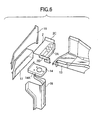
- Fig. 6 is an exploded perspective view of the main portions of a first embodiment of a vehicle body structure to which the above-mentioned hood hinge structure according to the invention is applied.
- the strut tower which is composed of a wheel apron upper 17, a wheel apron lower 18 and a suspension upper bracket 14 for storing a suspension therein
- the vehicle body a frame upper 2
- a stepped portion 2A which is situated lower than the normal surface (the upper surface of the frame upper 2).
- an overlapping flange 2C which is inclined obliquely upwardly, and the overlapping flange 2C is overlapped with a front pillar 12 (see Figs. 7A-7C) so that the frame upper 2 and front pillar 12 are continuously connected together.
- an overlapping flange 2D which is extended from the front end portion of the frame upper 2, is overlapped with the upper surface of the suspension upper bracket 14 so that they are continuously connected together.
- the suspension upper bracket 14 can receive loads smoothly through its three shelf surfaces in the longitudinal direction thereof, thereby being able to enhance the suspension rigidity and vehicle body rigidity.
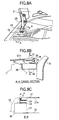
- Figs. 7A-7C show an example of a vehicle body structure to which the above-mentioned hood hinge structure are applied.
- Fig. 7A is a perspective view of the main portions of the example after it is assembled.
- Fig. 7B is a section view taken along the arrow line E-E shown in Fig. 7A.
- Fig. 7C is an arrow view taken along the arrow mark D shown in Fig. 7A.
- a stepped portion 2A which is situated lower than the normal surface, or, the upper surface of the frame upper 2.
- a suspension upper bracket 14 forming the upper surface portion of the strut tower is formed lower than the normal surface of the vehicle body 2. Due to this structure, even in the case that a clearance between the suspension upper bracket 14 and the hood 1 cannot be increased, a sufficient shock-absorbing stroke can be secured.
- the shape of the hinge lower including the shape of the fragile portion and the mode for fixing the hinge lower to the hood; the mode for hinge connecting together the hinge lower and hinge upper; the shape of the stepped portion (it may also be composed of several stepped portions) ; the shape of the shock-absorbing member including a fragile portion and the mode for fixing the shock-absorbing member to the vehicle body; the mode for forming the bending promoting shape in the hood; the shape of the frame upper constituting the vehicle body and the mode for connecting the frame upper to the frame side upper, strut tower, front bulkhead and front pillar; and, the shape and form of the strut tower including the structure associated with the suspension upper bracket and wheel apron lower.
- the engine room side of the vehicle body serving as a hinge lower fixing portion is formed as a stepped portion which is situated on the lower side.
- a hinge upper fixing portion is disposed such that it is opposed to the stepped portion.
- the side edge portion of the hood can be made easy to deform along the shape of the pedestrian's head, so that the shock surface pressure can be lowered to thereby relieve the shock and, at the same time, the side edge portion of the deformed hood can be contacted with the upper end portions of the respective hinge surfaces of the hinge upper and hinge lower to thereby facilitate the occurrence of bending moment around the hinge axial center, which can promote the bending deformation of the hinge portion.
- the shock-absorbing member is formed integral with the hinge lower, the fixation of the hinge lower side to the vehicle body and the shock-absorbing function can be realized at the same time by a single member, thereby being able to reduce the number of parts as well as simplify the parts mounting operation.
- the hinge lower in case where there is formed a fragile portion between the hinge lower fixing portion of the vehicle body and the connecting portion of the hinge lower and the hinge upper, the hinge lower can be deformed while absorbing the shock effectively. Further, in case where the fragile portion is formed as a bent portion which can be bent formed on the engine room side, the vertical length of the hinge surface is decreased and the fixing bolt mounting operation space is increased to thereby be able to enhance the operation efficiency; and, the drop and deformation of the hinge portion into the interior of the engine room is promoted to thereby be able to contribute toward expanding the shock-absorbing stroke further.
- a vehicle body structure including a hood hinge for hinge connecting together a hinge lower to be fixed to a vehicle body and a hinge upper to be fixed to a hood, on the engine room side of the vehicle body ranging from a strut tower thereof to a bulkhead thereof, there is formed a stepped portion which is situated lower than the normal surface of the vehicle body, and a hinge upper fixing portion is disposed such that it is opposed to the stepped portion.
- the upper surface portion of the strut tower is formed lower than the normal surface of the vehicle body, even in a structure where a clearance between a suspension upper bracket and the hood cannot be widened, a sufficient shock-absorbing stroke can be secured.
- a hood hinge and body structure which not only can secure a sufficient shock-absorbing stroke in the hinge portion while maintaining the low hood surface but also are enhanced in the parts mounting operation efficiency.
Applications Claiming Priority (2)
| Application Number | Priority Date | Filing Date | Title |
|---|---|---|---|
| JP2000340258A JP4647080B2 (ja) | 2000-11-08 | 2000-11-08 | 車両のフードヒンジおよび車体構造 |
| JP2000340258 | 2000-11-08 |
Publications (2)
| Publication Number | Publication Date |
|---|---|
| EP1205366A1 EP1205366A1 (en) | 2002-05-15 |
| EP1205366B1 true EP1205366B1 (en) | 2005-05-11 |
Family
ID=18815200
Family Applications (1)
| Application Number | Title | Priority Date | Filing Date |
|---|---|---|---|
| EP01126448A Expired - Lifetime EP1205366B1 (en) | 2000-11-08 | 2001-11-08 | A hood hinge and body structure |
Country Status (4)
| Country | Link |
|---|---|
| US (1) | US6817435B2 (ja) |
| EP (1) | EP1205366B1 (ja) |
| JP (1) | JP4647080B2 (ja) |
| DE (1) | DE60110724T2 (ja) |
Families Citing this family (23)
| Publication number | Priority date | Publication date | Assignee | Title |
|---|---|---|---|---|
| GB0121523D0 (en) * | 2001-09-06 | 2001-10-24 | Itw Ltd | Hinge assembly |
| JP3883989B2 (ja) * | 2003-07-11 | 2007-02-21 | 本田技研工業株式会社 | 前部車体構造 |
| DE102004011334B4 (de) * | 2004-03-09 | 2006-03-09 | Adam Opel Ag | Vorderbau für ein Kraftfahrzeug |
| DE102005010412A1 (de) | 2005-03-07 | 2006-09-14 | Innotec Forschungs- Und Entwicklungs-Gmbh | Passives Fußgängerschutz-Fronthaubenscharnier |
| JP4779460B2 (ja) * | 2005-06-23 | 2011-09-28 | マツダ株式会社 | 車両の安全装置 |
| EP1842745B1 (en) * | 2006-04-04 | 2011-08-17 | Ford Global Technologies, LLC | A bonnet bumpstop for a vehicle |
| KR100737959B1 (ko) * | 2006-09-26 | 2007-07-13 | 쌍용자동차 주식회사 | 자동차용 후드 힌지장치의 충격흡수구조 |
| US7690722B2 (en) * | 2007-05-21 | 2010-04-06 | Honda Motor Co., Ltd. | Energy absorbing vehicle hood stopper assembly |
| JP5088122B2 (ja) * | 2007-12-13 | 2012-12-05 | トヨタ自動車株式会社 | フード構造 |
| JP2008230605A (ja) * | 2008-05-22 | 2008-10-02 | Toyota Boshoku Corp | 衝撃吸収構造 |
| JP5073619B2 (ja) * | 2008-09-02 | 2012-11-14 | 本田技研工業株式会社 | 車体前部構造 |
| US8336666B2 (en) * | 2008-10-24 | 2012-12-25 | Honda Motor Co., Ltd. | Hood hinge |
| US7987939B2 (en) * | 2008-12-04 | 2011-08-02 | Honda Motor Co., Ltd. | Hood system with multiple open positions |
| DE102009040402B4 (de) * | 2009-09-07 | 2019-12-19 | Bayerische Motoren Werke Aktiengesellschaft | Kraftfahrzeug mit einer Fahrzeugklappe und mindestens einem Scharnier |
| DE102010007898A1 (de) | 2010-02-13 | 2011-08-18 | Volkswagen AG, 38440 | Vorderwagen eines Fahrzeugs |
| US9783152B2 (en) * | 2011-10-11 | 2017-10-10 | GM Global Technology Operations LLC | Vehicle impact reduction structure |
| US8662571B2 (en) | 2012-01-17 | 2014-03-04 | Nissan North America, Inc. | Vehicle hood energy absorbing assembly |
| JP5951315B2 (ja) * | 2012-03-27 | 2016-07-13 | ダイハツ工業株式会社 | 車体前部の衝撃吸収構造 |
| GB2503496B (en) | 2012-06-27 | 2017-09-13 | Aston Martin Lagonda Ltd | Vehicle assembly |
| EP3331751A4 (en) * | 2015-08-06 | 2019-03-20 | PSA Automobiles SA | SHOCK ABSORBERS FOR THE HOOD OF A VEHICLE |
| CN105216876A (zh) * | 2015-10-29 | 2016-01-06 | 北京新能源汽车股份有限公司 | 车身结构及具有其的电动汽车 |
| JP6548084B2 (ja) * | 2016-04-21 | 2019-07-24 | スズキ株式会社 | 車体側部構造 |
| FR3097584B1 (fr) | 2019-06-21 | 2023-12-29 | Psa Automobiles Sa | Charnière de capot de véhicule automobile anti-basculement et procédé de montage du capot |
Family Cites Families (36)
| Publication number | Priority date | Publication date | Assignee | Title |
|---|---|---|---|---|
| DE1104728B (de) | 1958-04-03 | 1961-04-13 | Netzsch Maschinenfabrik | Texturkamera |
| GB1438703A (en) * | 1972-11-29 | 1976-06-09 | Gen Motors Corp | Energy-absorbing vehicle body end structure electrostatographic apparatus comprising a movable imaging |
| FR2272866B1 (ja) * | 1974-05-30 | 1978-12-22 | Peugeot & Renault | |
| GB1536139A (en) * | 1975-03-14 | 1978-12-20 | Nat Res Dev | Vehicle with safety device |
| US4012807A (en) * | 1975-10-06 | 1977-03-22 | General Motors Corporation | Vehicle body hood hinge |
| US4069550A (en) * | 1976-11-03 | 1978-01-24 | General Motors Corporation | Closure panel hinge |
| DE2814107A1 (de) * | 1978-04-01 | 1979-10-04 | Volkswagenwerk Ag | Sicherheitseinrichtung zum schutz von fussgaengern |
| US4186476A (en) * | 1978-09-13 | 1980-02-05 | General Motors Corporation | Method for precise fitting of motor vehicle front end sheet metal |
| JPS6010934Y2 (ja) * | 1979-02-27 | 1985-04-12 | マツダ株式会社 | ヒンジブラケツト取付構造 |
| DE2934060A1 (de) * | 1979-08-23 | 1981-03-26 | Daimler-Benz Aktiengesellschaft, 70567 Stuttgart | Kraftfahrzeug, insbesondere personenkraftwagen, mit nachgiebigen karosseriefrontteilen |
| JPS6113407Y2 (ja) * | 1980-07-02 | 1986-04-25 | ||
| JPS5715771A (en) * | 1980-07-04 | 1982-01-27 | Kensuke Asakura | Destroying of concrete building |
| JPS6314468A (ja) * | 1986-07-07 | 1988-01-21 | Hitachi Ltd | 電荷移送形固体撮像素子 |
| JPH051500Y2 (ja) * | 1986-07-15 | 1993-01-14 | ||
| US4727621A (en) * | 1986-11-19 | 1988-03-01 | General Motors Corporation | Multiposition hinge |
| US4839941A (en) * | 1987-12-28 | 1989-06-20 | Ford Motor Company | Elevating and traversing hood hinge |
| US5557829A (en) * | 1995-03-28 | 1996-09-24 | Chrysler Corporation | Vehicle multi-link hinge flush positioning arrangement |
| JP3417146B2 (ja) * | 1995-06-02 | 2003-06-16 | 日産自動車株式会社 | 車両用フード支持構造 |
| DE19615744C1 (de) * | 1996-04-20 | 1997-06-05 | Daimler Benz Ag | Kraftfahrzeug mit mehreren Karosserieteilen |
| JPH09315266A (ja) | 1996-05-31 | 1997-12-09 | Mitsubishi Motors Corp | 車両用フード装置 |
| JP3518233B2 (ja) | 1997-03-19 | 2004-04-12 | 三菱自動車工業株式会社 | 車両用フード装置 |
| FR2772700B1 (fr) * | 1997-12-19 | 2000-02-04 | Peugeot | Procede de protection des pietons en cas de choc frontal avec un vehicule automobile et dispositif de mise en oeuvre du procede |
| JPH11198859A (ja) * | 1998-01-13 | 1999-07-27 | Nissan Motor Co Ltd | 車両フード後端部構造 |
| JP3506904B2 (ja) * | 1998-04-03 | 2004-03-15 | 本田技研工業株式会社 | 車両のフード用ヒンジ |
| JP3901847B2 (ja) * | 1998-06-19 | 2007-04-04 | 本田技研工業株式会社 | フード取付構造 |
| JP3460794B2 (ja) * | 1998-06-26 | 2003-10-27 | 本田技研工業株式会社 | フード取付構造 |
| JP3687086B2 (ja) * | 1998-09-30 | 2005-08-24 | マツダ株式会社 | 車両用前部構造 |
| JP3320681B2 (ja) * | 1999-07-19 | 2002-09-03 | 本田技研工業株式会社 | 車両用フード装置 |
| JP2001055170A (ja) * | 1999-08-18 | 2001-02-27 | Honda Motor Co Ltd | 車両用ボンネット構造 |
| EP1078826B1 (en) * | 1999-08-21 | 2002-01-02 | Ford Global Technologies, Inc., A subsidiary of Ford Motor Company | Pedestrian safety module device |
| DE19957870A1 (de) * | 1999-12-01 | 2001-06-07 | Volkswagen Ag | Sicherheitseinrichtung an einem Fahrzeug zum Schutz von Fußgängern |
| JP2001354164A (ja) * | 2000-06-14 | 2001-12-25 | Isuzu Motors Ltd | 車体のエンジンフードヒンジ |
| US6378640B1 (en) * | 2000-09-29 | 2002-04-30 | International Truck Intellectual Property Company, L.L.C. | Device and method to hold sound insulation in vehicle hood |
| KR20020030658A (ko) * | 2000-10-19 | 2002-04-25 | 류정열 | 자동차의 본네트용 힌지 |
| US6415882B1 (en) * | 2001-11-05 | 2002-07-09 | Ford Global Technologies, Inc. | Deployable hinge for pedestrian protection vehicle hood |
| US6439330B1 (en) * | 2001-11-05 | 2002-08-27 | Ford Global Technologies, Inc. | Vehicle hood deployment device for pedestrian protection |
-
2000
- 2000-11-08 JP JP2000340258A patent/JP4647080B2/ja not_active Expired - Fee Related
-
2001
- 2001-11-07 US US09/986,095 patent/US6817435B2/en not_active Expired - Lifetime
- 2001-11-08 EP EP01126448A patent/EP1205366B1/en not_active Expired - Lifetime
- 2001-11-08 DE DE60110724T patent/DE60110724T2/de not_active Expired - Lifetime
Also Published As
| Publication number | Publication date |
|---|---|
| US6817435B2 (en) | 2004-11-16 |
| US20020053118A1 (en) | 2002-05-09 |
| EP1205366A1 (en) | 2002-05-15 |
| DE60110724D1 (de) | 2005-06-16 |
| DE60110724T2 (de) | 2005-10-13 |
| JP4647080B2 (ja) | 2011-03-09 |
| JP2002145121A (ja) | 2002-05-22 |
Similar Documents
| Publication | Publication Date | Title |
|---|---|---|
| EP1205366B1 (en) | A hood hinge and body structure | |
| US6619730B2 (en) | Vehicle body having a strutting configuration at a bottom side of the vehicle body | |
| JP4736609B2 (ja) | 自動車のフェンダーパネル取付構造 | |
| EP1346887B1 (en) | Fender structure | |
| US7448674B2 (en) | Device for absorbing lateral forces in a side impact in a motor vehicle | |
| US20100194145A1 (en) | Energy absorbing structure for a vehicle | |
| US4789199A (en) | Vehicle underbody structure | |
| JP2007137224A (ja) | 車体前部構造 | |
| US6979053B2 (en) | Reinforcement structure for front end module carrier | |
| JP5151495B2 (ja) | 自動車のフードストッパ構造 | |
| JP2003048498A (ja) | バンパステー及び車両ボディ前部緩衝装置 | |
| JP5614663B2 (ja) | 車体前部の構造 | |
| JP2006224806A (ja) | フェンダ支持構造 | |
| KR100692532B1 (ko) | 차량 범퍼 충격흡수 조립체 | |
| KR100579875B1 (ko) | 범퍼 스테이 및 이를 적용한 자동차용 범퍼 어셈블리 | |
| JPH10258773A (ja) | 車両用フード装置 | |
| JP4038902B2 (ja) | スタビライザー取り付けブラケット構造 | |
| JP2006168523A (ja) | 車両用牽引フックの取付構造 | |
| JP3644317B2 (ja) | スタビライザ支持構造 | |
| JP4245701B2 (ja) | 自動車の前部車体構造 | |
| JP4003221B2 (ja) | 車両の前部車体構造 | |
| KR102119447B1 (ko) | 휠하우스 보강 구조 | |
| JP6893385B2 (ja) | 車両前部構造 | |
| JP4582307B2 (ja) | 車体前部構造 | |
| KR100353691B1 (ko) | 자동차의 보행자 보호를 위한 크로즈 박스형 카울 패널구조 |
Legal Events
| Date | Code | Title | Description |
|---|---|---|---|
| PUAI | Public reference made under article 153(3) epc to a published international application that has entered the european phase |
Free format text: ORIGINAL CODE: 0009012 |
|
| AK | Designated contracting states |
Kind code of ref document: A1 Designated state(s): AT BE CH CY DE DK ES FI FR GB GR IE IT LI LU MC NL PT SE TR |
|
| AX | Request for extension of the european patent |
Free format text: AL;LT;LV;MK;RO;SI |
|
| 17P | Request for examination filed |
Effective date: 20020904 |
|
| AKX | Designation fees paid |
Designated state(s): DE FR GB |
|
| 17Q | First examination report despatched |
Effective date: 20030331 |
|
| GRAP | Despatch of communication of intention to grant a patent |
Free format text: ORIGINAL CODE: EPIDOSNIGR1 |
|
| GRAS | Grant fee paid |
Free format text: ORIGINAL CODE: EPIDOSNIGR3 |
|
| GRAA | (expected) grant |
Free format text: ORIGINAL CODE: 0009210 |
|
| AK | Designated contracting states |
Kind code of ref document: B1 Designated state(s): DE FR GB |
|
| REG | Reference to a national code |
Ref country code: GB Ref legal event code: FG4D |
|
| REG | Reference to a national code |
Ref country code: IE Ref legal event code: FG4D |
|
| REF | Corresponds to: |
Ref document number: 60110724 Country of ref document: DE Date of ref document: 20050616 Kind code of ref document: P |
|
| PLBE | No opposition filed within time limit |
Free format text: ORIGINAL CODE: 0009261 |
|
| STAA | Information on the status of an ep patent application or granted ep patent |
Free format text: STATUS: NO OPPOSITION FILED WITHIN TIME LIMIT |
|
| 26N | No opposition filed |
Effective date: 20060214 |
|
| EN | Fr: translation not filed | ||
| PG25 | Lapsed in a contracting state [announced via postgrant information from national office to epo] |
Ref country code: FR Free format text: LAPSE BECAUSE OF NON-PAYMENT OF DUE FEES Effective date: 20051130 |
|
| PG25 | Lapsed in a contracting state [announced via postgrant information from national office to epo] |
Ref country code: FR Free format text: LAPSE BECAUSE OF NON-PAYMENT OF DUE FEES Effective date: 20050511 |
|
| PGFP | Annual fee paid to national office [announced via postgrant information from national office to epo] |
Ref country code: GB Payment date: 20081105 Year of fee payment: 8 |
|
| GBPC | Gb: european patent ceased through non-payment of renewal fee |
Effective date: 20091108 |
|
| PG25 | Lapsed in a contracting state [announced via postgrant information from national office to epo] |
Ref country code: GB Free format text: LAPSE BECAUSE OF NON-PAYMENT OF DUE FEES Effective date: 20091108 |
|
| PGFP | Annual fee paid to national office [announced via postgrant information from national office to epo] |
Ref country code: DE Payment date: 20161101 Year of fee payment: 16 |
|
| REG | Reference to a national code |
Ref country code: DE Ref legal event code: R082 Ref document number: 60110724 Country of ref document: DE Representative=s name: VOSSIUS & PARTNER PATENTANWAELTE RECHTSANWAELT, DE Ref country code: DE Ref legal event code: R081 Ref document number: 60110724 Country of ref document: DE Owner name: SUBARU CORPORATION, JP Free format text: FORMER OWNER: FUJI JUKOGYO K.K., TOKIO/TOKYO, JP |
|
| REG | Reference to a national code |
Ref country code: DE Ref legal event code: R119 Ref document number: 60110724 Country of ref document: DE |
|
| PG25 | Lapsed in a contracting state [announced via postgrant information from national office to epo] |
Ref country code: DE Free format text: LAPSE BECAUSE OF NON-PAYMENT OF DUE FEES Effective date: 20180602 |