EP1201477A2 - Fahrzeug mit reduzierter Emission von schädlichen Abgasbestandteilen - Google Patents
Fahrzeug mit reduzierter Emission von schädlichen Abgasbestandteilen Download PDFInfo
- Publication number
- EP1201477A2 EP1201477A2 EP01124868A EP01124868A EP1201477A2 EP 1201477 A2 EP1201477 A2 EP 1201477A2 EP 01124868 A EP01124868 A EP 01124868A EP 01124868 A EP01124868 A EP 01124868A EP 1201477 A2 EP1201477 A2 EP 1201477A2
- Authority
- EP
- European Patent Office
- Prior art keywords
- engine
- catalytic converter
- fuel supply
- amount
- oxygen
- Prior art date
- Legal status (The legal status is an assumption and is not a legal conclusion. Google has not performed a legal analysis and makes no representation as to the accuracy of the status listed.)
- Granted
Links
Images


Classifications
-
- B—PERFORMING OPERATIONS; TRANSPORTING
- B60—VEHICLES IN GENERAL
- B60W—CONJOINT CONTROL OF VEHICLE SUB-UNITS OF DIFFERENT TYPE OR DIFFERENT FUNCTION; CONTROL SYSTEMS SPECIALLY ADAPTED FOR HYBRID VEHICLES; ROAD VEHICLE DRIVE CONTROL SYSTEMS FOR PURPOSES NOT RELATED TO THE CONTROL OF A PARTICULAR SUB-UNIT
- B60W10/00—Conjoint control of vehicle sub-units of different type or different function
- B60W10/04—Conjoint control of vehicle sub-units of different type or different function including control of propulsion units
- B60W10/06—Conjoint control of vehicle sub-units of different type or different function including control of propulsion units including control of combustion engines
-
- B—PERFORMING OPERATIONS; TRANSPORTING
- B60—VEHICLES IN GENERAL
- B60K—ARRANGEMENT OR MOUNTING OF PROPULSION UNITS OR OF TRANSMISSIONS IN VEHICLES; ARRANGEMENT OR MOUNTING OF PLURAL DIVERSE PRIME-MOVERS IN VEHICLES; AUXILIARY DRIVES FOR VEHICLES; INSTRUMENTATION OR DASHBOARDS FOR VEHICLES; ARRANGEMENTS IN CONNECTION WITH COOLING, AIR INTAKE, GAS EXHAUST OR FUEL SUPPLY OF PROPULSION UNITS IN VEHICLES
- B60K6/00—Arrangement or mounting of plural diverse prime-movers for mutual or common propulsion, e.g. hybrid propulsion systems comprising electric motors and internal combustion engines
- B60K6/20—Arrangement or mounting of plural diverse prime-movers for mutual or common propulsion, e.g. hybrid propulsion systems comprising electric motors and internal combustion engines the prime-movers consisting of electric motors and internal combustion engines, e.g. HEVs
- B60K6/42—Arrangement or mounting of plural diverse prime-movers for mutual or common propulsion, e.g. hybrid propulsion systems comprising electric motors and internal combustion engines the prime-movers consisting of electric motors and internal combustion engines, e.g. HEVs characterised by the architecture of the hybrid electric vehicle
- B60K6/44—Series-parallel type
- B60K6/445—Differential gearing distribution type
-
- B—PERFORMING OPERATIONS; TRANSPORTING
- B60—VEHICLES IN GENERAL
- B60K—ARRANGEMENT OR MOUNTING OF PROPULSION UNITS OR OF TRANSMISSIONS IN VEHICLES; ARRANGEMENT OR MOUNTING OF PLURAL DIVERSE PRIME-MOVERS IN VEHICLES; AUXILIARY DRIVES FOR VEHICLES; INSTRUMENTATION OR DASHBOARDS FOR VEHICLES; ARRANGEMENTS IN CONNECTION WITH COOLING, AIR INTAKE, GAS EXHAUST OR FUEL SUPPLY OF PROPULSION UNITS IN VEHICLES
- B60K6/00—Arrangement or mounting of plural diverse prime-movers for mutual or common propulsion, e.g. hybrid propulsion systems comprising electric motors and internal combustion engines
- B60K6/20—Arrangement or mounting of plural diverse prime-movers for mutual or common propulsion, e.g. hybrid propulsion systems comprising electric motors and internal combustion engines the prime-movers consisting of electric motors and internal combustion engines, e.g. HEVs
- B60K6/42—Arrangement or mounting of plural diverse prime-movers for mutual or common propulsion, e.g. hybrid propulsion systems comprising electric motors and internal combustion engines the prime-movers consisting of electric motors and internal combustion engines, e.g. HEVs characterised by the architecture of the hybrid electric vehicle
- B60K6/48—Parallel type
-
- F—MECHANICAL ENGINEERING; LIGHTING; HEATING; WEAPONS; BLASTING
- F02—COMBUSTION ENGINES; HOT-GAS OR COMBUSTION-PRODUCT ENGINE PLANTS
- F02D—CONTROLLING COMBUSTION ENGINES
- F02D41/00—Electrical control of supply of combustible mixture or its constituents
- F02D41/02—Circuit arrangements for generating control signals
- F02D41/021—Introducing corrections for particular conditions exterior to the engine
- F02D41/0235—Introducing corrections for particular conditions exterior to the engine in relation with the state of the exhaust gas treating apparatus
- F02D41/0295—Control according to the amount of oxygen that is stored on the exhaust gas treating apparatus
-
- F—MECHANICAL ENGINEERING; LIGHTING; HEATING; WEAPONS; BLASTING
- F02—COMBUSTION ENGINES; HOT-GAS OR COMBUSTION-PRODUCT ENGINE PLANTS
- F02D—CONTROLLING COMBUSTION ENGINES
- F02D41/00—Electrical control of supply of combustible mixture or its constituents
- F02D41/02—Circuit arrangements for generating control signals
- F02D41/14—Introducing closed-loop corrections
- F02D41/1438—Introducing closed-loop corrections using means for determining characteristics of the combustion gases; Sensors therefor
- F02D41/1444—Introducing closed-loop corrections using means for determining characteristics of the combustion gases; Sensors therefor characterised by the characteristics of the combustion gases
- F02D41/1446—Introducing closed-loop corrections using means for determining characteristics of the combustion gases; Sensors therefor characterised by the characteristics of the combustion gases the characteristics being exhaust temperatures
-
- B—PERFORMING OPERATIONS; TRANSPORTING
- B60—VEHICLES IN GENERAL
- B60K—ARRANGEMENT OR MOUNTING OF PROPULSION UNITS OR OF TRANSMISSIONS IN VEHICLES; ARRANGEMENT OR MOUNTING OF PLURAL DIVERSE PRIME-MOVERS IN VEHICLES; AUXILIARY DRIVES FOR VEHICLES; INSTRUMENTATION OR DASHBOARDS FOR VEHICLES; ARRANGEMENTS IN CONNECTION WITH COOLING, AIR INTAKE, GAS EXHAUST OR FUEL SUPPLY OF PROPULSION UNITS IN VEHICLES
- B60K6/00—Arrangement or mounting of plural diverse prime-movers for mutual or common propulsion, e.g. hybrid propulsion systems comprising electric motors and internal combustion engines
- B60K6/20—Arrangement or mounting of plural diverse prime-movers for mutual or common propulsion, e.g. hybrid propulsion systems comprising electric motors and internal combustion engines the prime-movers consisting of electric motors and internal combustion engines, e.g. HEVs
- B60K6/22—Arrangement or mounting of plural diverse prime-movers for mutual or common propulsion, e.g. hybrid propulsion systems comprising electric motors and internal combustion engines the prime-movers consisting of electric motors and internal combustion engines, e.g. HEVs characterised by apparatus, components or means specially adapted for HEVs
- B60K6/26—Arrangement or mounting of plural diverse prime-movers for mutual or common propulsion, e.g. hybrid propulsion systems comprising electric motors and internal combustion engines the prime-movers consisting of electric motors and internal combustion engines, e.g. HEVs characterised by apparatus, components or means specially adapted for HEVs characterised by the motors or the generators
- B60K2006/268—Electric drive motor starts the engine, i.e. used as starter motor
-
- B—PERFORMING OPERATIONS; TRANSPORTING
- B60—VEHICLES IN GENERAL
- B60L—PROPULSION OF ELECTRICALLY-PROPELLED VEHICLES; SUPPLYING ELECTRIC POWER FOR AUXILIARY EQUIPMENT OF ELECTRICALLY-PROPELLED VEHICLES; ELECTRODYNAMIC BRAKE SYSTEMS FOR VEHICLES IN GENERAL; MAGNETIC SUSPENSION OR LEVITATION FOR VEHICLES; MONITORING OPERATING VARIABLES OF ELECTRICALLY-PROPELLED VEHICLES; ELECTRIC SAFETY DEVICES FOR ELECTRICALLY-PROPELLED VEHICLES
- B60L2240/00—Control parameters of input or output; Target parameters
- B60L2240/40—Drive Train control parameters
- B60L2240/44—Drive Train control parameters related to combustion engines
- B60L2240/445—Temperature
-
- B—PERFORMING OPERATIONS; TRANSPORTING
- B60—VEHICLES IN GENERAL
- B60W—CONJOINT CONTROL OF VEHICLE SUB-UNITS OF DIFFERENT TYPE OR DIFFERENT FUNCTION; CONTROL SYSTEMS SPECIALLY ADAPTED FOR HYBRID VEHICLES; ROAD VEHICLE DRIVE CONTROL SYSTEMS FOR PURPOSES NOT RELATED TO THE CONTROL OF A PARTICULAR SUB-UNIT
- B60W2510/00—Input parameters relating to a particular sub-units
- B60W2510/06—Combustion engines, Gas turbines
- B60W2510/068—Engine exhaust temperature
-
- B—PERFORMING OPERATIONS; TRANSPORTING
- B60—VEHICLES IN GENERAL
- B60W—CONJOINT CONTROL OF VEHICLE SUB-UNITS OF DIFFERENT TYPE OR DIFFERENT FUNCTION; CONTROL SYSTEMS SPECIALLY ADAPTED FOR HYBRID VEHICLES; ROAD VEHICLE DRIVE CONTROL SYSTEMS FOR PURPOSES NOT RELATED TO THE CONTROL OF A PARTICULAR SUB-UNIT
- B60W2710/00—Output or target parameters relating to a particular sub-units
- B60W2710/06—Combustion engines, Gas turbines
- B60W2710/0616—Position of fuel or air injector
-
- B—PERFORMING OPERATIONS; TRANSPORTING
- B60—VEHICLES IN GENERAL
- B60W—CONJOINT CONTROL OF VEHICLE SUB-UNITS OF DIFFERENT TYPE OR DIFFERENT FUNCTION; CONTROL SYSTEMS SPECIALLY ADAPTED FOR HYBRID VEHICLES; ROAD VEHICLE DRIVE CONTROL SYSTEMS FOR PURPOSES NOT RELATED TO THE CONTROL OF A PARTICULAR SUB-UNIT
- B60W2710/00—Output or target parameters relating to a particular sub-units
- B60W2710/06—Combustion engines, Gas turbines
- B60W2710/0644—Engine speed
-
- F—MECHANICAL ENGINEERING; LIGHTING; HEATING; WEAPONS; BLASTING
- F02—COMBUSTION ENGINES; HOT-GAS OR COMBUSTION-PRODUCT ENGINE PLANTS
- F02D—CONTROLLING COMBUSTION ENGINES
- F02D2200/00—Input parameters for engine control
- F02D2200/02—Input parameters for engine control the parameters being related to the engine
- F02D2200/08—Exhaust gas treatment apparatus parameters
- F02D2200/0814—Oxygen storage amount
-
- F—MECHANICAL ENGINEERING; LIGHTING; HEATING; WEAPONS; BLASTING
- F02—COMBUSTION ENGINES; HOT-GAS OR COMBUSTION-PRODUCT ENGINE PLANTS
- F02D—CONTROLLING COMBUSTION ENGINES
- F02D41/00—Electrical control of supply of combustible mixture or its constituents
- F02D41/02—Circuit arrangements for generating control signals
- F02D41/04—Introducing corrections for particular operating conditions
- F02D41/042—Introducing corrections for particular operating conditions for stopping the engine
-
- Y—GENERAL TAGGING OF NEW TECHNOLOGICAL DEVELOPMENTS; GENERAL TAGGING OF CROSS-SECTIONAL TECHNOLOGIES SPANNING OVER SEVERAL SECTIONS OF THE IPC; TECHNICAL SUBJECTS COVERED BY FORMER USPC CROSS-REFERENCE ART COLLECTIONS [XRACs] AND DIGESTS
- Y02—TECHNOLOGIES OR APPLICATIONS FOR MITIGATION OR ADAPTATION AGAINST CLIMATE CHANGE
- Y02T—CLIMATE CHANGE MITIGATION TECHNOLOGIES RELATED TO TRANSPORTATION
- Y02T10/00—Road transport of goods or passengers
- Y02T10/60—Other road transportation technologies with climate change mitigation effect
- Y02T10/62—Hybrid vehicles
Definitions
- the present invention relates to a technology for reducing emission of NOx from an internal combustion engine of a vehicle into the atmosphere.
- a catalytic converter having a three-way catalyst is installed in an automobile for reducing emission of harmful air pollutants such as NOx, HC and CO contained in an exhaust gas discharged from an engine of the automobile.
- the three-way catalyst has a function that promotes reaction among those pollutants to generate harmless components such as N 2 , CO, and H 2 O.
- the catalytic converter including the catalyst for removing NOx in the exhaust system of the engine may cause a problem when the engine is temporarily stopped.
- the engine is generally stopped by discontinuing a fuel supply.
- the engine will continue to be operated under the inertia for a while after discontinuing the fuel supply.
- an oxygen-rich intake air is discharged into the catalytic converter that accumulates oxygen at every temporary stop of the engine.
- HC and CO flowing into the catalytic converter together with NOx will react with oxygen accumulated therein instead of causing the reaction between NOx and HC, CO to generate a harmless component N 2 .
- NOx is not removed and then discharged into the atmosphere.
- the aforementioned problem is particularly critical for operating an eco-running vehicle or a hybrid vehicle in which the engine is frequently stopped and restarted.
- the invention provides a vehicle that includes a power-train including an engine, a motor at least temporarily connected to the engine, a battery serving to supply power to the motor, and a generator selectively driven by at least the engine to charge the battery; a catalytic converter that purifies an exhaust gas from the engine; and a controller that controls fuel supply to the engine, determines whether an engine stop condition for stopping the engine is established and whether an engine re-start condition for re-starting the engine is established, on the basis of a traveling state of the vehicle, and discontinues the fuel supply to the engine when it is determined that the engine stop condition is established, and controls an engine speed such that an amount of oxygen accumulated in the catalytic converter during an engine stop is adjusted to be within a preset range, and re-starts the fuel supply for driving the engine when it is determined that the engine re-start condition is established, while temporarily increasing an amount of fuel supplied to the engine.
- An operation of the engine may be controlled such that the engine speed upon discontinuation of the fuel supply is within a preset range.
- the fuel supply may be discontinued when a revolution phase of the engine is within a preset range.
- the engine speed may be controlled after discontinuation of the fuel supply to the engine such that an amount of oxygen to be accumulated in the catalytic converter during an engine stop is controlled to a saturated amount of oxygen that can be accumulated in the catalytic converter.
- An operation of the engine may be controlled such that a temperature of the catalytic converter upon discontinuation of the fuel supply is within a preset range.
- the catalytic converter When the engine is stopped by discontinuing the fuel supply, the catalytic converter accumulates oxygen fed from the engine that races under the inertia after the discontinuation of the fuel supply.
- the amount of oxygen accumulated in the catalytic converter may be controlled to be within a preset range for reaction with an appropriate amount of HC fed into the catalytic converter by temporarily increasing the amount of the fuel supply.
- the additional fuel may be supplied at the same timing as a normal fuel supply timing, or may be supplied at a different timing.
- the amount of oxygen fed and accumulated into the catalytic converter while racing of the engine after discontinuation of the fuel supply is determined by an engine speed when a fuel supply is discontinued. Accordingly, if the engine speed upon start of discontinuation of the fuel supply is controlled to be within a preset range prior to the discontinuation of the fuel supply, the amount of oxygen to be accumulated in the catalytic converter upon the engine stop may be controlled within a preset range more accurately.
- the aforementioned control to adjust the engine speed into the preset range may be executed by controlling an intake air of the engine, driving the engine by the motor, and suppressing the engine operation by the generator.
- the amount of oxygen fed and accumulated into the catalytic converter while racing of the engine after discontinuation of the fuel supply is determined by a revolution phase of the engine when the fuel supply is discontinued. Accordingly if discontinuation of the fuel supply is controlled to start at a timing when the revolution phase of the engine falls within the preset range, the amount of oxygen fed and accumulated into the catalytic converter resulting from the engine racing after discontinuing the fuel supply can be controlled to be within the preset range.
- the amount of oxygen accumulated in the catalytic converter is controlled to a saturated amount, the accumulated amount is determined in accordance with a temperature of the catalytic converter.
- the amount of the accumulated oxygen at the engine stop thus, can be accurately derived from the temperature of the catalytic converter. Accordingly, the amount of the accumulated oxygen can be controlled to be within the preset range by controlling the catalytic converter temperature.
- the amount of oxygen accumulated into the catalytic converter may be changed depending on the catalytic converter temperature. In case of a high catalytic converter temperature, the accumulated amount of oxygen is increased. Therefore, the accumulated amount of oxygen may further be accurately controlled to be within the preset range by controlling the catalytic converter temperature in addition to the engine speed control or the engine revolution phase control.
- the catalytic converter temperature may be controlled by performing control of either a fuel supply amount, an intake air supply amount, an ignition timing, or a combination thereof.
- Fig. 1 schematically shows the construction of a power-train system employed in a hybrid vehicle according to one preferred embodiment of the invention.
- an internal combustion engine 1 is operatively connected to a generator 3 and a motor 4 via a drive coupling device 2 including a planetary gear set, such that power is transmitted among the engine 1, the generator 3 and the motor 4.
- the engine 1, the drive coupling device 2, the generator 3 and the motor 4 constitute a power-train for driving the hybrid vehicle.
- a transmission 5 is coupled to the power-train via a shaft of the motor 4.
- power is transmitted between the power-train of the engine 1, the generator 3, and the motor 4, and drive wheels 7a, 7b of the vehicle, via the transmission 5 and a pair of driving axles 6a, 6b.
- a differential gear system 8 is incorporated in the transmission 5, such that power for rotating the wheels 7a, 7b may be differentially transmitted to the driving axles 6a, 6b via the transmission 5.
- a battery 9 is electrically connected to the generator 3 and the motor 4 via an inverter 10.
- the generator 3 functions to charge the battery 9 by generating power when the vehicle is driven under the inertia or by the engine 1 during deceleration.
- the motor 4 functions to drive the vehicle as needed, using the battery 9 as an electric power supply. While the generator 3 and the motor 4 are separately provided in the embodiment of Fig. 1, a so-called "motor/generator" as an integral device may be employed in place of the generator 3 and the motor 4.
- the motor/generator selectively functions as a motor or a generator, and the function of the motor/generator may be changed through switching of an electric circuit incorporated therein.
- a catalytic converter 11 including a three-way catalyst is incorporated in an exhaust system of the engine 1 such that NOx, HC and CO contained in the exhaust gas discharged from the engine react with one another to generate harmless components such as N 2 , CO 2 , and H 2 O.
- An electronic control unit (ECU) 12 functions to control the engine 1, generator 3, motor 4, and transmission 5 in a manner as described below such that the vehicle of reduced emission type of the invention can be operated.
- the ECU 12 receives signals concerning the operation of the invention indicating a depression amount of an accelerator pedal Dp, a vehicle speed Sv, a temperature Te of the engine 1, a revolution phase ⁇ e of an engine crankshaft, and a temperature Tc of the catalytic converter.
- step S10 Upon start of the vehicle by turning on a key switch (not shown), required data for controlling are read in step S10 of the flowchart in Fig. 2. Then in step S20, driving of the vehicle is controlled on the basis of the data read in step S10.
- the control executed in step S20 includes a steering control and a vehicle speed control to be performed by a vehicle operator.
- step S30 In the course of the vehicle driving control reflected by the vehicle operator, the process proceeds to step S30 in which it is determined whether a condition that allows the engine stop during operation of the vehicle is established. The process returns to step S10 until YES is obtained in step S30.
- step S40 when it is determined in step S30 that a predetermined condition under which the engine is allowed or desired to temporarily stop is established.
- the predetermined condition may include stopping at a red traffic light for a time period exceeding a certain time length, running at a substantially low speed owing to a traffic jam, stopping the vehicle for a certain time period or longer or switching from the engine running mode to the motor running mode.
- step S40 it is determined whether an engine speed Ne is within a preset range, i.e., N1 ⁇ Ne ⁇ N2.
- the Ne may range between, for example, 800-80 rpm (Nl) and 800+80 rpm (N2). If YES is obtained in step S40, the process proceeds to step S50.
- step S60 the engine speed is controlled to be within a preset range by, for example, controlling at least one of a fuel supply amount and an air supply amount, applying a load of the generator 3 to the engine, using the motor 4 to accelerate the engine or performing a suitable combination of the aforementioned controls.
- the process then returns from step S60 to step S10 to execute the next cycle of the control routine, and in step S40, it is determined whether the engine speed is within the preset range again.
- the increase or decrease in the engine speed may be controlled in a stepped manner in a preferred embodiment.
- step S50 a moment when a phase angle ⁇ e of the crankshaft relative to one cylinder, e.g., the first cylinder, of the engine is within a range, that is, TDC ⁇ ⁇ ( ⁇ : set as a very small angle) is detected. If such moment is detected, the process proceeds to step S70.
- TDC ⁇ ⁇ ⁇ : set as a very small angle
- step S70 it is determined whether a catalytic temperature Tc of a catalytic converter is within a range between T1 and T2.
- the temperature T2 may be set to the value indicating a temperature limit above which an amount of oxygen accumulated in the catalyst becomes excessive.
- the temperature T2 may further be set to a value to which the catalytic temperature may be easily controlled by controlling the fuel supply amount, intake air amount, or an ignition timing.
- the temperature T1 may be set to an arbitrary value so long as an appropriate temperature range is obtained between the temperatures T1 and T2. If YES is obtained in step S70, the process proceeds to step S80 in which the fuel supply is discontinued.
- step S70 If N0 is obtained in step S70, the process proceeds to step S90, in which the catalytic temperature is controlled to be within the preset range by controlling the fuel supply amount, intake air amount, or ignition timing. Like the engine speed control executed in step S60, the catalytic temperature control may be executed in a stepped manner by repeatedly executing the control routine until YES is obtained in step S70.
- the amount of oxygen accumulated in the catalytic converter 11 after the engine stop can be always controlled within a preset range.
- additional fuel is supplied in order to feed appropriate amounts of HC and CO to the catalytic converter such that the controlled amount of oxygen can react with the HC and CO without deteriorating emission and fuel efficiency.
- the amount of the additional fuel to be temporarily added is determined such that removal of NOx cannot be prevented by the controlled amount of oxygen.
- the additional fuel supply may be performed by increasing the fuel at a normal fuel supply timing or supplying the additional fuel at a different fuel supply timing.
- the aforementioned fuel addition control is executed at re-starting of the engine in a temporary stopped state by the vehicle driving control in step S20.
- the flowchart shown in Fig. 2 incorporates three possible control schemes. All those control schemes do not have to be executed to achieve the object of the invention. At least one of control schemes for controlling the engine speed to be within a preset range before discontinuing the fuel supply (S40 and S60) and for controlling the rotation phase of the engine to be within a preset range before discontinuing the fuel supply (S50) may be executed.
- the control scheme for controlling the catalytic temperature to be within a preset range before discontinuing the fuel supply (S70 and S90) may be combined with any one of the aforementioned control schemes, or may be omitted.
- an amount of oxygen accumulated in the catalytic converter is controlled by the engine speed Ne, the crank shaft angle phase ⁇ e, or combination thereof, or further the catalytic converter temperature. Therefore at re-starting of the engine, the amount of the fuel supplied to the engine may be temporarily increased such that the oxygen accumulated in the catalytic converter is reacted with HC and CO to be removed before reaction of the oxygen with NOx, HC, CO, respectively by the catalytic converter and an appropriate amount of HC and CO is fed to the catalytic converter.
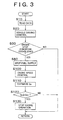
- Fig. 3 shows a flowchart of another embodiment of the invention.
- step of the control scheme which is the same as that shown in Fig. 2 will be designated with the same number of step shown in Fig. 2.
- step S30 when it is determined that the engine stop condition is established in step S30, the fuel supply is immediately discontinued in the subsequent step S80. Then the amount of oxygen to be accumulated in the catalytic converter after stopping of the engine is controlled.
- step S100 the engine speed is controlled, and then in step S110, an oxygen amount Qs accumulated in the catalytic converter is estimated.
- the engine speed is controlled by stopping the engine operation under the inertia by controlling at least one of an intake throttle and a load of the generator, or by retarding the engine operation under the inertia by means of the motor.
- the engine speed after discontinuing the fuel supply can be obtained by the aforementioned engine speed control. Accordingly the oxygen amount to be accumulated in the catalytic converter after the engine stop may be estimated.
- step S120 it is determined whether the estimated oxygen amount Qs reaches a maximum oxygen amount that can be retained by the catalytic converter, that is, a saturated oxygen amount Qso.
- the saturated oxygen amount Qso is determined on the basis of the catalytic converter temperature Tc read in step S10.
- the process will return from step S120 to step S10 until YES is obtained in step S120.
- the control routine executes reading of the data and proceeds to step S100 and then to S110. If the estimated oxygen amount Qs reaches the saturated oxygen amount Qso, that is, YES is obtained in step S120, the process proceeds to step S130 in which an engine is stopped. The engine is stopped by operating the load of the generator 3 or the motor 4 reversely.
- the amount of oxygen accumulated in the catalytic converter has reached the saturated oxygen amount determined on the basis of the catalytic converter temperature. So upon re-starting of the engine, appropriate amount of the additional fuel can be temporarily supplied such that the accumulated oxygen can be removed by reaction with HC and CO prior to reaction among NOx, HC and CO in the catalytic converter.
- An amount of oxygen accumulated in a catalytic converter (11) after an engine stop by discontinuing a fuel supply to an engine (1) is controlled by controlling an engine speed, controlling an engine revolution phase into a preset range, feeding air into the catalytic converter (11) until the accumulated amount of oxygen becomes saturated, and controlling a catalytic converter temperature.
- Increase of an appropriate amount of the fuel at re-starting of the engine (1) may prevent oxygen from deteriorating the NOx removing function without degrading an emission and the fuel efficiency.
Landscapes
- Engineering & Computer Science (AREA)
- Chemical & Material Sciences (AREA)
- Combustion & Propulsion (AREA)
- Mechanical Engineering (AREA)
- Transportation (AREA)
- General Engineering & Computer Science (AREA)
- Exhaust Gas After Treatment (AREA)
- Control Of Vehicle Engines Or Engines For Specific Uses (AREA)
- Electrical Control Of Air Or Fuel Supplied To Internal-Combustion Engine (AREA)
- Output Control And Ontrol Of Special Type Engine (AREA)
- Combined Controls Of Internal Combustion Engines (AREA)
Applications Claiming Priority (4)
| Application Number | Priority Date | Filing Date | Title |
|---|---|---|---|
| JP2000328047 | 2000-10-27 | ||
| JP2000328047 | 2000-10-27 | ||
| JP2001004496 | 2001-01-12 | ||
| JP2001004496A JP3982178B2 (ja) | 2000-10-27 | 2001-01-12 | 有害ガス成分排出抑制型車輌 |
Publications (3)
| Publication Number | Publication Date |
|---|---|
| EP1201477A2 true EP1201477A2 (de) | 2002-05-02 |
| EP1201477A3 EP1201477A3 (de) | 2004-02-25 |
| EP1201477B1 EP1201477B1 (de) | 2008-09-10 |
Family
ID=26602882
Family Applications (1)
| Application Number | Title | Priority Date | Filing Date |
|---|---|---|---|
| EP01124868A Expired - Lifetime EP1201477B1 (de) | 2000-10-27 | 2001-10-18 | Fahrzeug mit reduzierter Emission von schädlichen Abgasbestandteilen |
Country Status (4)
| Country | Link |
|---|---|
| US (1) | US6581373B2 (de) |
| EP (1) | EP1201477B1 (de) |
| JP (1) | JP3982178B2 (de) |
| DE (1) | DE60135719D1 (de) |
Cited By (6)
| Publication number | Priority date | Publication date | Assignee | Title |
|---|---|---|---|---|
| FR2845128A1 (fr) * | 2002-10-01 | 2004-04-02 | Toyota Motor Co Ltd | Dispositif de generation de puissance, dispositif de generation de puissance hybride, procede de commande de ceux-ci, et vehicule hybride |
| DE102006005716A1 (de) * | 2006-02-08 | 2007-08-09 | Bayerische Motoren Werke Ag | Verfahren zum Betreiben einer Brennkraftmaschine |
| EP2599679A4 (de) * | 2010-07-26 | 2016-04-20 | Toyota Motor Co Ltd | Steuerungsvorrichtung für ein hybridfahrzeug |
| WO2016058858A1 (de) * | 2014-10-13 | 2016-04-21 | Continental Automotive Gmbh | Antriebsvorrichtung für ein kraftfahrzeug |
| EP2078651A4 (de) * | 2006-10-27 | 2017-11-22 | Toyota Jidosha Kabushiki Kaisha | Leistungsabgabevorrichtung, verbrennungsmotorvorrichtung und steuerverfahren dafür |
| EP3450734A1 (de) * | 2017-09-05 | 2019-03-06 | Toyota Jidosha Kabushiki Kaisha | Steuerungssystem für verbrennungsmotor |
Families Citing this family (21)
| Publication number | Priority date | Publication date | Assignee | Title |
|---|---|---|---|---|
| JP3815256B2 (ja) * | 2001-05-29 | 2006-08-30 | トヨタ自動車株式会社 | 車輌用間歇運転内燃機関のNOx排出抑制運転方法 |
| JP3948254B2 (ja) * | 2001-11-12 | 2007-07-25 | 株式会社デンソー | 内燃機関の排気浄化装置 |
| JP2005273530A (ja) * | 2004-03-24 | 2005-10-06 | Toyota Motor Corp | 内燃機関の制御装置およびこれを備える自動車 |
| US7100362B2 (en) * | 2004-07-30 | 2006-09-05 | Ford Global Technologies, Llc | Vehicle and method for operating a vehicle to reduce exhaust emissions |
| JP4449917B2 (ja) * | 2006-02-14 | 2010-04-14 | トヨタ自動車株式会社 | 動力出力装置、その制御方法及び動力出力装置を搭載した車両 |
| DE602007011241D1 (de) * | 2007-06-19 | 2011-01-27 | Ford Global Tech Llc | Hybridfahrzeug, Antriebssystem für ein Hybridfahrzeug und Verfahren für eine Abgasverarbeitungsvorrichtung in einem solchen System |
| JP5118443B2 (ja) * | 2007-11-05 | 2013-01-16 | 三菱ふそうトラック・バス株式会社 | ハイブリッド電気自動車の排気浄化装置 |
| EP2210788B1 (de) | 2007-11-05 | 2017-05-31 | Mitsubishi Fuso Truck and Bus Corporation | Abgasreiniger für ein elektrisches hybridfahrzeug |
| JP5118442B2 (ja) * | 2007-11-05 | 2013-01-16 | 三菱ふそうトラック・バス株式会社 | ハイブリッド電気自動車の排気浄化装置 |
| JP2010071116A (ja) * | 2008-09-16 | 2010-04-02 | Hitachi Ltd | エンジンの制御装置 |
| US7931002B1 (en) * | 2010-02-17 | 2011-04-26 | Ford Global Technologies, Llc | Method for starting an engine |
| US8972150B2 (en) * | 2010-06-01 | 2015-03-03 | GM Global Technology Operations LLC | Selective cylinder disablement control systems and methods |
| US9303576B2 (en) * | 2012-02-24 | 2016-04-05 | Ford Global Technologies, Llc | Method for controlling an engine |
| JP6044089B2 (ja) * | 2012-03-15 | 2016-12-14 | 日産自動車株式会社 | 内燃機関の制御装置 |
| JP2014092097A (ja) * | 2012-11-05 | 2014-05-19 | Toyota Motor Corp | 内燃機関の始動制御装置 |
| JP6642220B2 (ja) * | 2016-04-12 | 2020-02-05 | スズキ株式会社 | 排気浄化装置 |
| JP6319357B2 (ja) * | 2016-04-27 | 2018-05-09 | マツダ株式会社 | 車両の制御装置 |
| JP6617750B2 (ja) | 2017-05-23 | 2019-12-11 | トヨタ自動車株式会社 | 車両駆動装置の制御装置 |
| WO2020126010A1 (en) * | 2018-12-20 | 2020-06-25 | Volvo Truck Corporation | A method for controlling the braking of a vehicle comprising a diesel engine |
| JP7190048B2 (ja) * | 2019-08-02 | 2022-12-14 | 日産自動車株式会社 | 内燃機関の制御方法及び内燃機関の制御装置 |
| JP7395007B2 (ja) * | 2020-09-25 | 2023-12-08 | 日産自動車株式会社 | 車両の制御方法及び車両の制御装置 |
Family Cites Families (26)
| Publication number | Priority date | Publication date | Assignee | Title |
|---|---|---|---|---|
| US3650345A (en) * | 1969-12-09 | 1972-03-21 | Michel N Yardney | Control system for alternately battery-operated and engine-powered vehicle |
| JP2548065Y2 (ja) * | 1991-09-03 | 1997-09-17 | 三菱自動車工業株式会社 | ハイブリッド車の排ガス浄化装置 |
| AU666188B2 (en) | 1992-05-15 | 1996-02-01 | Mitsubishi Jidosha Kogyo Kabushiki Kaisha | Operating method for a hybrid car |
| US5319921A (en) | 1992-08-04 | 1994-06-14 | Ford Motor Company | Catalytic converter efficiency monitoring |
| DE4315278A1 (de) | 1993-05-07 | 1994-11-10 | Siemens Ag | Verfahren und Einrichtung zur Dosierung eines Reduktionsmittels in ein stickoxidhaltiges Abgas |
| ES2122602T3 (es) | 1994-08-10 | 1998-12-16 | Siemens Ag | Procedimiento para la conversion catalitica de oxidos de nitrogeno contenidos en el gas de escape de un motor de combustion interna. |
| JP3661071B2 (ja) | 1996-04-10 | 2005-06-15 | 本田技研工業株式会社 | ハイブリッド車両の制御装置 |
| JP3177153B2 (ja) | 1996-04-10 | 2001-06-18 | 本田技研工業株式会社 | ハイブリッド車両の制御装置 |
| US5785137A (en) * | 1996-05-03 | 1998-07-28 | Nevcor, Inc. | Hybrid electric vehicle catalyst control |
| DE19629163C1 (de) | 1996-07-19 | 1997-10-09 | Daimler Benz Ag | Verfahren und Vorrichtung zum stickoxidemissionsarmen Betrieb eines Verbrennungsmotors |
| JPH1047048A (ja) | 1996-08-02 | 1998-02-17 | Toyota Motor Corp | 内燃機関の排気浄化装置 |
| JP2982746B2 (ja) | 1997-06-06 | 1999-11-29 | トヨタ自動車株式会社 | ハイブリッド車両の内燃機関制御装置 |
| JP3096447B2 (ja) * | 1997-09-17 | 2000-10-10 | 本田技研工業株式会社 | ハイブリッド車両の制御装置 |
| JP3096446B2 (ja) | 1997-09-17 | 2000-10-10 | 本田技研工業株式会社 | ハイブリッド車両の制御装置 |
| JPH11178111A (ja) | 1997-12-17 | 1999-07-02 | Hitachi Ltd | ハイブリット電気車 |
| JP2000054826A (ja) | 1998-08-11 | 2000-02-22 | Nissan Motor Co Ltd | エンジンの排気浄化装置 |
| JP3760053B2 (ja) | 1998-09-30 | 2006-03-29 | 本田技研工業株式会社 | 内燃機関の排気ガス浄化装置 |
| JP3374773B2 (ja) * | 1998-12-28 | 2003-02-10 | トヨタ自動車株式会社 | 内燃機関の触媒劣化検出装置 |
| JP3376948B2 (ja) * | 1999-03-19 | 2003-02-17 | トヨタ自動車株式会社 | ハイブリット車の排気浄化制御装置 |
| JP2000303828A (ja) * | 1999-04-20 | 2000-10-31 | Toyota Motor Corp | ハイブリット車の排気浄化装置 |
| JP4042270B2 (ja) * | 1999-05-24 | 2008-02-06 | トヨタ自動車株式会社 | 内燃機関の始動制御装置 |
| DE10026471B4 (de) * | 1999-06-25 | 2007-07-05 | Man Nutzfahrzeuge Ag | Antriebsstrang eines Kraftfahrzeuges |
| JP2001037008A (ja) * | 1999-07-21 | 2001-02-09 | Nissan Motor Co Ltd | ハイブリッド車両の制御装置 |
| JP2001055941A (ja) * | 1999-08-16 | 2001-02-27 | Honda Motor Co Ltd | エンジン自動始動停止制御装置 |
| US6425365B1 (en) * | 2000-10-20 | 2002-07-30 | Ford Global Technologies, Inc. | Internal combustion engine shutdown method and control system |
| FR2825415B1 (fr) * | 2002-05-28 | 2009-08-21 | Toyota Motor Co Ltd | Procede et appareil de commande d'un moteur a combustion interne capable de fonctionnements intermittents |
-
2001
- 2001-01-12 JP JP2001004496A patent/JP3982178B2/ja not_active Expired - Fee Related
- 2001-09-24 US US09/961,067 patent/US6581373B2/en not_active Expired - Lifetime
- 2001-10-18 EP EP01124868A patent/EP1201477B1/de not_active Expired - Lifetime
- 2001-10-18 DE DE60135719T patent/DE60135719D1/de not_active Expired - Lifetime
Non-Patent Citations (1)
| Title |
|---|
| None |
Cited By (10)
| Publication number | Priority date | Publication date | Assignee | Title |
|---|---|---|---|---|
| FR2845128A1 (fr) * | 2002-10-01 | 2004-04-02 | Toyota Motor Co Ltd | Dispositif de generation de puissance, dispositif de generation de puissance hybride, procede de commande de ceux-ci, et vehicule hybride |
| US7055312B2 (en) | 2002-10-01 | 2006-06-06 | Toyota Jidosha Kabushiki Kaisha | Power output apparatus, hybrid power output apparatus, method of controlling the same, and hybrid vehicle |
| CN100387819C (zh) * | 2002-10-01 | 2008-05-14 | 丰田自动车株式会社 | 动力输出装置、混合动力输出装置及其控制方法以及混合动力车辆 |
| DE10345561B4 (de) * | 2002-10-01 | 2010-07-15 | Toyota Jidosha Kabushiki Kaisha, Toyota-shi | Leistungsabgabevorrichtung, Hybridleistungsabgabevorrichtung, Verfahren zum Steuern derselben und Hybridfahrzeug |
| DE102006005716A1 (de) * | 2006-02-08 | 2007-08-09 | Bayerische Motoren Werke Ag | Verfahren zum Betreiben einer Brennkraftmaschine |
| EP2078651A4 (de) * | 2006-10-27 | 2017-11-22 | Toyota Jidosha Kabushiki Kaisha | Leistungsabgabevorrichtung, verbrennungsmotorvorrichtung und steuerverfahren dafür |
| EP2599679A4 (de) * | 2010-07-26 | 2016-04-20 | Toyota Motor Co Ltd | Steuerungsvorrichtung für ein hybridfahrzeug |
| WO2016058858A1 (de) * | 2014-10-13 | 2016-04-21 | Continental Automotive Gmbh | Antriebsvorrichtung für ein kraftfahrzeug |
| EP3450734A1 (de) * | 2017-09-05 | 2019-03-06 | Toyota Jidosha Kabushiki Kaisha | Steuerungssystem für verbrennungsmotor |
| US10711720B2 (en) | 2017-09-05 | 2020-07-14 | Toyota Jidosha Kabushiki Kaisha | Control system for internal combustion engine |
Also Published As
| Publication number | Publication date |
|---|---|
| JP3982178B2 (ja) | 2007-09-26 |
| US20020052266A1 (en) | 2002-05-02 |
| JP2002201983A (ja) | 2002-07-19 |
| EP1201477A3 (de) | 2004-02-25 |
| EP1201477B1 (de) | 2008-09-10 |
| US6581373B2 (en) | 2003-06-24 |
| DE60135719D1 (de) | 2008-10-23 |
Similar Documents
| Publication | Publication Date | Title |
|---|---|---|
| EP1201477B1 (de) | Fahrzeug mit reduzierter Emission von schädlichen Abgasbestandteilen | |
| EP1201478B1 (de) | Hybridfahrzeug mit NOx-Reduktionssystem und Verfahren zum Betreiben desselbem | |
| US6810977B2 (en) | Hybrid vehicle and method in which the engine is preheated before start | |
| US6742327B2 (en) | Method and apparatus for controlling internal combustion engine capable of intermittent operations | |
| JP3788736B2 (ja) | エンジンの自動停止始動制御装置 | |
| CN100510364C (zh) | 临时停机的车辆用内燃机的运行方法和运行控制装置 | |
| US6494809B1 (en) | Engine control apparatus and engine control method | |
| JP2004100680A (ja) | ハイブリッド電気自動車のエンジン制御システム及び制御方法 | |
| JP2002371877A (ja) | 車載内燃機関の自動停止制御装置 | |
| JP2001234838A (ja) | 車両のエンジン自動停止再始動装置 | |
| JP3614021B2 (ja) | 車両の自己診断装置 | |
| JP2003138958A (ja) | 車両駆動装置及び車両駆動装置用プログラム | |
| JP3588673B2 (ja) | アイドルストップ車両 | |
| EP1223324B1 (de) | System und Verfahren zur Unterdrückung der Kohlenwasserstoffentladung für Kraftfahrzeuge | |
| JP3758419B2 (ja) | アイドルストップ車両 | |
| JP2005155399A (ja) | 自動車およびその制御方法 | |
| JP4112351B2 (ja) | 自動車のエンジン停止制御装置 | |
| JP2000177412A (ja) | ハイブリッド車両の制御装置 | |
| JP4069589B2 (ja) | 内燃機関の制御装置 | |
| JP3350520B2 (ja) | ハイブリッド車両 | |
| KR100992809B1 (ko) | 하이브리드 차량의 아이들 스톱/스타트 제어방법 | |
| JP4200605B2 (ja) | クラッチ制御装置 | |
| KR20210034737A (ko) | 타행 주행 기능 및 isg 기능 제어 방법 및 그 방법이 적용된 차량 | |
| JP5811026B2 (ja) | 車両の制御装置 | |
| JPH08164775A (ja) | 車両用駆動装置の制御装置 |
Legal Events
| Date | Code | Title | Description |
|---|---|---|---|
| PUAI | Public reference made under article 153(3) epc to a published international application that has entered the european phase |
Free format text: ORIGINAL CODE: 0009012 |
|
| 17P | Request for examination filed |
Effective date: 20011018 |
|
| AK | Designated contracting states |
Kind code of ref document: A2 Designated state(s): AT BE CH CY DE DK ES FI FR GB GR IE IT LI LU MC NL PT SE TR |
|
| AX | Request for extension of the european patent |
Free format text: AL;LT;LV;MK;RO;SI |
|
| PUAL | Search report despatched |
Free format text: ORIGINAL CODE: 0009013 |
|
| AK | Designated contracting states |
Kind code of ref document: A3 Designated state(s): AT BE CH CY DE DK ES FI FR GB GR IE IT LI LU MC NL PT SE TR |
|
| AX | Request for extension of the european patent |
Extension state: AL LT LV MK RO SI |
|
| AKX | Designation fees paid |
Designated state(s): DE FR GB |
|
| GRAP | Despatch of communication of intention to grant a patent |
Free format text: ORIGINAL CODE: EPIDOSNIGR1 |
|
| RIC1 | Information provided on ipc code assigned before grant |
Ipc: B60K 6/445 20071001ALN20071008BHEP Ipc: B60W 20/00 20060101ALN20071008BHEP Ipc: B60W 10/06 20060101ALN20071008BHEP Ipc: F02D 41/14 20060101ALI20071008BHEP Ipc: F02D 41/02 20060101AFI20071008BHEP Ipc: B60K 6/48 20071001ALN20071008BHEP |
|
| RTI1 | Title (correction) |
Free format text: VEHICLE WITH REDUCED EMISSION OF HARMFUL COMPONENT |
|
| GRAS | Grant fee paid |
Free format text: ORIGINAL CODE: EPIDOSNIGR3 |
|
| GRAA | (expected) grant |
Free format text: ORIGINAL CODE: 0009210 |
|
| AK | Designated contracting states |
Kind code of ref document: B1 Designated state(s): DE FR GB |
|
| REG | Reference to a national code |
Ref country code: GB Ref legal event code: FG4D |
|
| REF | Corresponds to: |
Ref document number: 60135719 Country of ref document: DE Date of ref document: 20081023 Kind code of ref document: P |
|
| PLBE | No opposition filed within time limit |
Free format text: ORIGINAL CODE: 0009261 |
|
| STAA | Information on the status of an ep patent application or granted ep patent |
Free format text: STATUS: NO OPPOSITION FILED WITHIN TIME LIMIT |
|
| 26N | No opposition filed |
Effective date: 20090611 |
|
| REG | Reference to a national code |
Ref country code: GB Ref legal event code: 746 Effective date: 20110104 |
|
| PGFP | Annual fee paid to national office [announced via postgrant information from national office to epo] |
Ref country code: FR Payment date: 20121018 Year of fee payment: 12 |
|
| PGFP | Annual fee paid to national office [announced via postgrant information from national office to epo] |
Ref country code: GB Payment date: 20121017 Year of fee payment: 12 |
|
| GBPC | Gb: european patent ceased through non-payment of renewal fee |
Effective date: 20131018 |
|
| PG25 | Lapsed in a contracting state [announced via postgrant information from national office to epo] |
Ref country code: GB Free format text: LAPSE BECAUSE OF NON-PAYMENT OF DUE FEES Effective date: 20131018 |
|
| REG | Reference to a national code |
Ref country code: FR Ref legal event code: ST Effective date: 20140630 |
|
| PG25 | Lapsed in a contracting state [announced via postgrant information from national office to epo] |
Ref country code: FR Free format text: LAPSE BECAUSE OF NON-PAYMENT OF DUE FEES Effective date: 20131031 |
|
| PGFP | Annual fee paid to national office [announced via postgrant information from national office to epo] |
Ref country code: DE Payment date: 20161011 Year of fee payment: 16 |
|
| REG | Reference to a national code |
Ref country code: DE Ref legal event code: R119 Ref document number: 60135719 Country of ref document: DE |
|
| PG25 | Lapsed in a contracting state [announced via postgrant information from national office to epo] |
Ref country code: DE Free format text: LAPSE BECAUSE OF NON-PAYMENT OF DUE FEES Effective date: 20180501 |