EP1197617A1 - Befestigungsvorrichtung für einen Distanzhalter - Google Patents
Befestigungsvorrichtung für einen Distanzhalter Download PDFInfo
- Publication number
- EP1197617A1 EP1197617A1 EP02001407A EP02001407A EP1197617A1 EP 1197617 A1 EP1197617 A1 EP 1197617A1 EP 02001407 A EP02001407 A EP 02001407A EP 02001407 A EP02001407 A EP 02001407A EP 1197617 A1 EP1197617 A1 EP 1197617A1
- Authority
- EP
- European Patent Office
- Prior art keywords
- spacer
- wedge element
- connecting iron
- wedge
- iron
- Prior art date
- Legal status (The legal status is an assumption and is not a legal conclusion. Google has not performed a legal analysis and makes no representation as to the accuracy of the status listed.)
- Granted
Links
Images


Classifications
-
- E—FIXED CONSTRUCTIONS
- E04—BUILDING
- E04G—SCAFFOLDING; FORMS; SHUTTERING; BUILDING IMPLEMENTS OR AIDS, OR THEIR USE; HANDLING BUILDING MATERIALS ON THE SITE; REPAIRING, BREAKING-UP OR OTHER WORK ON EXISTING BUILDINGS
- E04G17/00—Connecting or other auxiliary members for forms, falsework structures, or shutterings
- E04G17/06—Tying means; Spacers ; Devices for extracting or inserting wall ties
- E04G17/064—Spacers placed on the bottom of the mould
Definitions
- the invention relates to a device with a spacer for a wall formwork for erecting a concrete wall on a concrete surface, using the spacer by means of a receiving opening for an upright reinforcement connection iron having fastening part and a wedge element that can be inserted into the receiving opening a connecting iron can be fixed.
- From DE-A-4439959 is a clamping device for fixing a spacer designed as a crossbar with end stops known.
- the wall form is used to set a spacer defined distance between two against the end stops tensioned formwork walls.
- the known clamping device consists of a U-shaped profile piece on the front side two diametrically opposite recesses for Insertion of the spacer are provided.
- the spacer is the profile piece to the connecting iron and the spacer in the recesses used.
- the guideline is used to fix between the spacer and Connection iron driven a wedge.
- the handling of the the three parts profile piece, clamping wedge and spacer existing arrangement proves to be practical Use as cumbersome.
- the inventor has the Task given a device of the aforementioned Kind of creating a quick with easy handling Setting the spacer allows with high accuracy.
- the solution to the problem according to the invention is that Wedge element between connecting iron and a counter surface of the fastener is driven and inserted Position the spacer fixed and the connecting iron as well abuts the counter surface of the fastening part.
- the wedge element fixes the spacer clamped to the connecting iron via a crossbar, i.e. at the
- the wedge is driven in with a clamping fixation of the cross bar positioned between wedge and connecting iron, the crossbar after wedging directly to the connecting iron is applied.
- the fastening part can consist of a piece of pipe that is put over the connecting iron. However, since this that is often not possible and is also cumbersome Fastening part preferably on the longitudinal side a receiving opening on that to form counter surfaces as undercut Groove is formed.
- the fastening part is preferred as a profile piece with a substantially U-shaped Cross-section formed, the free ends of the U-legs angled inwards to form the counter surfaces are. For easier centering of the profile piece on Connecting irons can be one or more of the U-legs Have kinks.
- the free ones Angled ends of the U-legs in such a way that they correspond with the corresponding Longitudinal grooves in the key element can be engaged are. This increases the stability of the entire arrangement.
- the crossbar inserted in the transverse groove can be used for arrangement the spacer of at least one bow-like Formation on the head part to be included. So that the spacer and the wedge element are preassembled so that each only two parts have to be delivered to the construction site.
- the wedge element directly as a holding part for one in this lockable spacer trained.
- the fastening part or the profile piece suitably exists made of metal.
- Fastening part made of a possibly fiber-reinforced plastic manufacture.
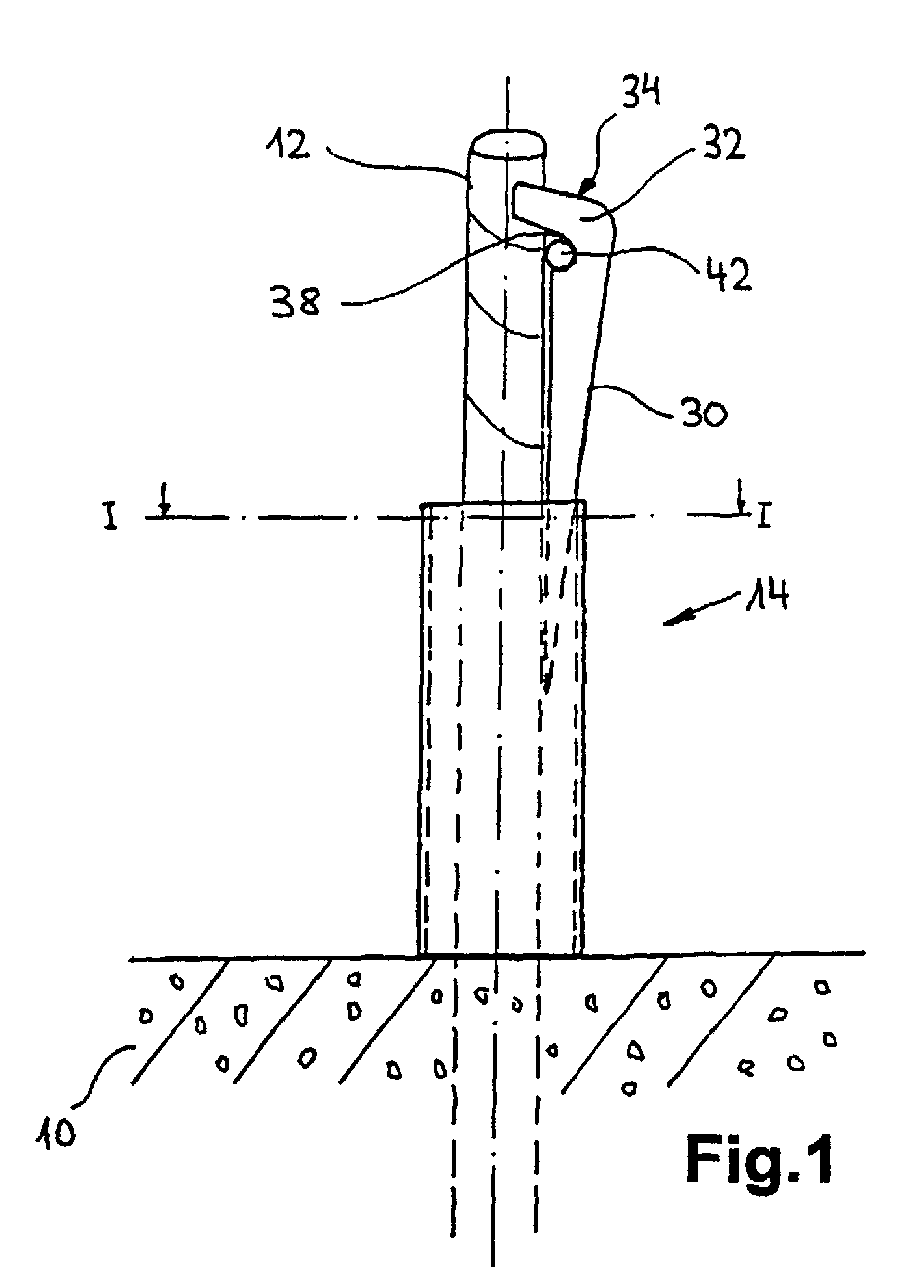
- a reinforcing connecting iron protrudes from a concrete floor 10 12 with a profile piece attached to this 14 with a substantially U-shaped cross section.
- the leg parts 16 go at one weak kink 18 in lower leg parts 20 over and form a relatively narrow radius in the profile base 22. Due to the special cross-sectional design of the profile piece 14 there is an automatic centering when applying of the profile piece to the connecting iron. The free Ends of the leg parts 16 are to form counter surfaces 24 angled inwards.
- the profile piece 14 has the shape of an undercut Groove 26 with a receiving opening 28 for the connecting iron 12.
- a wedge 30 is inserted into the undercut groove 26, on the one hand the reinforcing iron 12 and on the other hand the profile piece 14 rests on its counter surfaces 24.
- the wedge 30 has a striking surface 34 for a hammer forming, angled headboard 32 with a connecting iron 12 adapted section 36.
- the head part 32 of the key 30 arranged transverse groove 38 is a conventional one Spacer 40 with cross bar 42 and end stops 44 inserted from plastic.
- the profile piece 14 is connected to the corresponding connecting iron 12 created and the key 30 with the inserted in the transverse groove 38 Spacer 40 inserted into the profile piece 14.
- the manual force is sufficient to pre-fix the arrangement out.
- By moving the crossbar 42 in the transverse groove 38 as well as possibly turning the entire arrangement become the end stops 44 of the spacer 40 aligned with a guide line and centered the arrangement.
- the final fixation is done by hitting the hammer with a hammer Striking surface 34. Should the spacer 40 be incorrectly centered the wedge is very easy and quick by one from below against the wedge 30 or the cross bar 42 Loosen the hammer blow.
- Fig. 1 also shows easily that the inventive Universal arrangement for any connecting iron Diameter is suitable. According to the thickness of the Connection iron 12, the wedge 30 lowers more or less strong in the profile piece 14.
- the wedge element is as a holding part 46 for a conventional spacer 40 with cross bar 42 and end stops 44 made of plastic.
- the bracket part 46 is with a U-shaped sheet metal strip 48 made of spring steel fitted.
- the one in opposite bushings 50 cross bar 42 guided in the sheet metal strip 48 can be move freely by compressing the metal strip 48 and align it with a guideline. By the preload the sheet metal strip 48, the spacer 40 remains in any displacement position fixed automatically.
- the free ends of the legs 16 are such angled so that it has an end edge 25 in on the Engage grooves 31 formed on the outside of the wedge 30. This results in a wedge 30 inserted between them and the profile piece 14 a brace, which the stability the entire arrangement increased.
- the two point Leg parts 16 two kinks 18a, b, whereby the Centering of the profile piece 14 on differently dimensioned Connection iron 12 is further improved.
- brackets 33 are formed such that they Include crossbar 42 of spacer 40.
- This special Form of training of the head part 32 enables preassembly of wedge 30 with spacer 40, the cross bar 42 between transverse groove 38 and bracket 33 for straightening the spacer required game.
- Fig. 9 shows a wedge element 30, the head part 32 with bracket 33 adapted to the U-shaped cross section of a cross bar 42a is.
Landscapes
- Engineering & Computer Science (AREA)
- Architecture (AREA)
- Mechanical Engineering (AREA)
- Civil Engineering (AREA)
- Structural Engineering (AREA)
- Forms Removed On Construction Sites Or Auxiliary Members Thereof (AREA)
- Magnetically Actuated Valves (AREA)
- Joining Of Building Structures In Genera (AREA)
- Finishing Walls (AREA)
- Organic Low-Molecular-Weight Compounds And Preparation Thereof (AREA)
Abstract
Description
- Fig. 1
- eine Seitenansicht einer Anordnung mit eingesetztem Distanzhalter;
- Fig. 2
- einen Querschnitt durch die Anordnung von Fig. 1 nach deren Linie I-I;
- Fig. 3
- die Draufsicht auf die Anordnung von Fig. 1;
- Fig. 4
- eine Seitenansicht eines Keilelementes mit integriertem Distanzhalter;
- Fig. 5
- die Draufsicht auf das Keilelement von Fig. 4;
- Fig. 6
- eine Seitenansicht einer weiteren Anordnung mit eingesetztem Distanzhalter;
- Fig. 7
- die Draufsicht auf die Anordnung von Fig. 6 mit eingesetztem Distanzhalter;
- Fig. 8
- einen Querschnitt durch das Profilstück der Anordnung von Fig. 6;
- Fig. 9
- eine Variante der Anordnung von Fig. 6.
Claims (9)
- Vorrichtung mit einem Distanzhalter für eine Wandschalung zum Errichten einer Betonwand auf einem betonierten Untergrund (10), wobei der Distanzhalter (40) mittels eines eine Aufnahmeöffnung (28) für ein aufragendes Armierungsanschlusseisen (12) aufweisenden Befestigungsteiles (14) und eines in die Aufnahmeöffnung (28) einsetzbaren Keilelementes (30) an einem Anschlusseisen festlegbar ist,
dadurch gekennzeichnet, dass
das Keilelement (30) zwischen Anschlusseisen (12) und einer Gegenfläche (24) des Befestigungsteils (14) eintreibbar ist und in eingesetzter Lage den Distanzhalter (40) fixiert und dem Anschlusseisen (12) sowie der Gegenfläche (24) des Befestigungsteils (14) anliegt. - Vorrichtung nach Anspruch 1, dadurch gekennzeichnet, dass das Keilelement (30) den Distanzhalter (40) über einen Querstab (42) klemmend am Anschlusseisen (12) fixiert.
- Vorrichtung nach Anspruch 1, dadurch gekennzeichnet, dass das Keilelement (30) als Halterungsteil (46) für einen in diesem feststellbaren Distanzhalter (40) ausgebildet ist.
- Vorrichtung nach einem der Ansprüche 1 bis 3, dadurch gekennzeichnet, dass die Aufnahmeöffnung (28) des Befestigungsteils (14) zur Bildung von Gegenflächen (30) als hinterschnittene Nut (26) ausgebildet ist.
- Vorrichtung nach Anspruch 4, dadurch gekennzeichnet, dass das Befestigungsteil als Profilstück (14) mit einem im wesentlichen U-förmigen Querschnitt ausgebildet ist, wobei die freien Enden der U-Schenkel (16) unter Bildung der Gegenflächen (30) nach innen abgewinkelt sind.
- Vorrichtung nach Anspruch 5, dadurch gekennzeichnet, dass die freien Enden der U-Schenkel (16) zumindest je eine Knickstelle (18,18a,b) aufweisen.
- Vorrichtung nach Anspruch 5 oder 6, dadurch gekennzeichnet, dass die freien Enden der U-Schenkel (16) derart abgewinkelt sind, das ihre Endkanten (25) mit entsprechenden Längsnuten (31) im Keilelement (30) in Eingriff bringbar sind.
- Vorrichtung nach einem der Ansprüche 2 oder 4 bis 7, dadurch gekennzeichnet, dass in einem Kopfteil (32) des Keilelementes (30) eine Quernut (38) zur Aufnahme des Querstabes (42) des Distanzhalters (40) vorgesehen ist.
- Vorrichtung nach Anspruch 8, dadurch gekennzeichnet, dass der in die Quernut (38) eingesetzte Querstab (42) des Distanzhalters (40) von mindestens einer bügelartigen Ausformung (33) am Kopfteil (32) umfasst ist.
Applications Claiming Priority (5)
| Application Number | Priority Date | Filing Date | Title |
|---|---|---|---|
| CH75996 | 1996-03-22 | ||
| CH75996 | 1996-03-22 | ||
| CH75896 | 1996-03-22 | ||
| CH75896 | 1996-03-22 | ||
| EP97906072A EP0888486B1 (de) | 1996-03-22 | 1997-03-13 | Anschlaghalter für eine wandschalung |
Related Parent Applications (1)
| Application Number | Title | Priority Date | Filing Date |
|---|---|---|---|
| EP97906072A Division EP0888486B1 (de) | 1996-03-22 | 1997-03-13 | Anschlaghalter für eine wandschalung |
Publications (2)
| Publication Number | Publication Date |
|---|---|
| EP1197617A1 true EP1197617A1 (de) | 2002-04-17 |
| EP1197617B1 EP1197617B1 (de) | 2005-07-20 |
Family
ID=25685595
Family Applications (2)
| Application Number | Title | Priority Date | Filing Date |
|---|---|---|---|
| EP97906072A Expired - Lifetime EP0888486B1 (de) | 1996-03-22 | 1997-03-13 | Anschlaghalter für eine wandschalung |
| EP02001407A Expired - Lifetime EP1197617B1 (de) | 1996-03-22 | 1997-03-13 | Vorrichtung zum Befestigen eines Distanzhalters an einem Anschlusseisen |
Family Applications Before (1)
| Application Number | Title | Priority Date | Filing Date |
|---|---|---|---|
| EP97906072A Expired - Lifetime EP0888486B1 (de) | 1996-03-22 | 1997-03-13 | Anschlaghalter für eine wandschalung |
Country Status (5)
| Country | Link |
|---|---|
| EP (2) | EP0888486B1 (de) |
| AT (2) | ATE299979T1 (de) |
| AU (1) | AU2089897A (de) |
| DE (3) | DE19780234D2 (de) |
| WO (1) | WO1997036070A1 (de) |
Cited By (6)
| Publication number | Priority date | Publication date | Assignee | Title |
|---|---|---|---|---|
| AT413722B (de) * | 2001-11-19 | 2006-05-15 | System Albanese | Distanzhalter |
| EP2987924A1 (de) | 2014-08-18 | 2016-02-24 | Pino Albanese | Anschlaghalter für eine wandschalung |
| EP3029219A1 (de) | 2014-12-02 | 2016-06-08 | Pino Albanese | Verfahren zum setzen einer abstand-, anschlag- oder distanzhaltervorrichtung sowie ein abstand-, anschlag- oder distanzhalter |
| JP2017036605A (ja) * | 2015-08-10 | 2017-02-16 | 岡部株式会社 | 棒状部材の連結金具 |
| EP3358105A1 (de) | 2017-02-01 | 2018-08-08 | Pino Albanese | Verfahren zum verbinden eines distanzhalters mit einem anschlusseisen, einem keil, einer abstand- und anschlaghalteranordnung und einem halter |
| EP3636848A1 (de) * | 2018-09-27 | 2020-04-15 | Mägert Bautechnik AG | Keilelement, abstandhalter mit mindestens einem solchen keilelement, positioniervorrichtung mit einem solchen abstandhalter und verfahren zur positionierung von wandschalungen |
Families Citing this family (2)
| Publication number | Priority date | Publication date | Assignee | Title |
|---|---|---|---|---|
| CN107954358B (zh) * | 2017-11-11 | 2023-10-13 | 华强方特(芜湖)文化科技有限公司 | 一种可调节滚柱导绳器 |
| WO2021071327A2 (ko) * | 2019-10-11 | 2021-04-15 | 임태형 | 거푸집의 세퍼레이터 고정장치 |
Citations (4)
| Publication number | Priority date | Publication date | Assignee | Title |
|---|---|---|---|---|
| DE7215162U (de) * | 1972-04-21 | 1972-08-10 | Schwachula I Kg | Abstandhalter für Bewehrungsstäbe |
| DE4439959A1 (de) * | 1994-03-09 | 1995-09-21 | Maegert Bautechnik Ag | Verfahren zum Setzen eines Anschlag- oder Distanzhalters |
| DE29511258U1 (de) * | 1995-07-12 | 1995-11-09 | Metall- und Drucklufttechnik Trusetal GmbH, 98594 Trusetal | Vorrichtung zum Feststellen des Abstandes |
| DE29517487U1 (de) * | 1994-12-19 | 1995-12-21 | Albanese, Giulio, Winterthur | Anschlaghalterung für Wandschalungen |
-
1997
- 1997-03-13 AT AT02001407T patent/ATE299979T1/de active
- 1997-03-13 DE DE19780234T patent/DE19780234D2/de not_active Ceased
- 1997-03-13 EP EP97906072A patent/EP0888486B1/de not_active Expired - Lifetime
- 1997-03-13 AU AU20898/97A patent/AU2089897A/en not_active Abandoned
- 1997-03-13 DE DE59712375T patent/DE59712375D1/de not_active Expired - Lifetime
- 1997-03-13 WO PCT/CH1997/000107 patent/WO1997036070A1/de not_active Ceased
- 1997-03-13 EP EP02001407A patent/EP1197617B1/de not_active Expired - Lifetime
- 1997-03-13 DE DE59707918T patent/DE59707918D1/de not_active Expired - Lifetime
- 1997-03-13 AT AT97906072T patent/ATE221946T1/de active
Patent Citations (4)
| Publication number | Priority date | Publication date | Assignee | Title |
|---|---|---|---|---|
| DE7215162U (de) * | 1972-04-21 | 1972-08-10 | Schwachula I Kg | Abstandhalter für Bewehrungsstäbe |
| DE4439959A1 (de) * | 1994-03-09 | 1995-09-21 | Maegert Bautechnik Ag | Verfahren zum Setzen eines Anschlag- oder Distanzhalters |
| DE29517487U1 (de) * | 1994-12-19 | 1995-12-21 | Albanese, Giulio, Winterthur | Anschlaghalterung für Wandschalungen |
| DE29511258U1 (de) * | 1995-07-12 | 1995-11-09 | Metall- und Drucklufttechnik Trusetal GmbH, 98594 Trusetal | Vorrichtung zum Feststellen des Abstandes |
Cited By (7)
| Publication number | Priority date | Publication date | Assignee | Title |
|---|---|---|---|---|
| AT413722B (de) * | 2001-11-19 | 2006-05-15 | System Albanese | Distanzhalter |
| EP2987924A1 (de) | 2014-08-18 | 2016-02-24 | Pino Albanese | Anschlaghalter für eine wandschalung |
| EP3029219A1 (de) | 2014-12-02 | 2016-06-08 | Pino Albanese | Verfahren zum setzen einer abstand-, anschlag- oder distanzhaltervorrichtung sowie ein abstand-, anschlag- oder distanzhalter |
| JP2017036605A (ja) * | 2015-08-10 | 2017-02-16 | 岡部株式会社 | 棒状部材の連結金具 |
| EP3358105A1 (de) | 2017-02-01 | 2018-08-08 | Pino Albanese | Verfahren zum verbinden eines distanzhalters mit einem anschlusseisen, einem keil, einer abstand- und anschlaghalteranordnung und einem halter |
| EP3508667A1 (de) | 2017-02-01 | 2019-07-10 | Pino Albanese | Verfahren zum verbinden eines distanzhalters mit einem anschlusseisen, eine abstand- und anschlaghalteranordnung, ein keil und ein halter |
| EP3636848A1 (de) * | 2018-09-27 | 2020-04-15 | Mägert Bautechnik AG | Keilelement, abstandhalter mit mindestens einem solchen keilelement, positioniervorrichtung mit einem solchen abstandhalter und verfahren zur positionierung von wandschalungen |
Also Published As
| Publication number | Publication date |
|---|---|
| WO1997036070A1 (de) | 1997-10-02 |
| DE59712375D1 (de) | 2005-08-25 |
| ATE299979T1 (de) | 2005-08-15 |
| DE59707918D1 (de) | 2002-09-12 |
| EP0888486B1 (de) | 2002-08-07 |
| EP1197617B1 (de) | 2005-07-20 |
| ATE221946T1 (de) | 2002-08-15 |
| DE19780234D2 (de) | 1999-07-08 |
| AU2089897A (en) | 1997-10-17 |
| EP0888486A1 (de) | 1999-01-07 |
Similar Documents
| Publication | Publication Date | Title |
|---|---|---|
| DE3333619A1 (de) | Schalung fuer rundbauten | |
| DE2716864A1 (de) | Spannschloss | |
| EP1197617A1 (de) | Befestigungsvorrichtung für einen Distanzhalter | |
| DE102018101251A1 (de) | Profilschiene mit Stopfen zur Befestigung auf einer Verschalung | |
| DE4439959C2 (de) | Verfahren zum Setzen eines Anschlag- oder Distanzhalters | |
| DE2829941C3 (de) | Vorrictung zum Verbinden von Stahlbewehrungen | |
| DE1805629A1 (de) | Zarge fuer Tueren- bzw. Fenster | |
| DE3917150C2 (de) | ||
| DE3444801A1 (de) | Aus einem ankersteg und einem ankerdorn bestehender anker zum anbringen von wandbekleidungsplatten an bauwerkswaenden | |
| DE19700952C2 (de) | Vorrichtung zur Verankerung von Gerüsten | |
| AT401248B (de) | Vorrichtung zum einschlagen von isolierplatten in mauerwerk | |
| DE102012004022B3 (de) | Vorrichtung zum Richten einer durch Last und/oder Schlag verbogenen Dachrinne | |
| DE7302148U (de) | Schiene mit Befestigungseinrichtungen, insbesondere Bodenschiene für Haustüren | |
| DE9411784U1 (de) | Putzbrett zum Verputzen einer Wand im Bereich einer Wandaussparung | |
| EP3636848B1 (de) | Keilelement, abstandhalter mit mindestens einem solchen keilelement, positioniervorrichtung mit einem solchen abstandhalter und verfahren zur positionierung von wandschalungen | |
| EP0434603B1 (de) | Vorrichtung zur Fixierung der Lage von zwei zueinander in Abstand gegenüberstehenden Schalungswänden | |
| DE10252296A1 (de) | Distanzhalterkeil | |
| DE975906C (de) | Verankerung fuer Bewehrungsstaebe in Beton | |
| DE9016348U1 (de) | Einbauhilfe für Steigeisen | |
| EP1211368A1 (de) | Befestigungselement | |
| DE9404842U1 (de) | Vorrichtung zum Abschranken einer Gebäudeöffnung | |
| DE90135C (de) | ||
| CH710499A2 (de) | Verfahren zum Setzen einer Abstand-, Anschlag- oder Distanzhaltervorrichtung sowie einen Abstand-, Anschlag- oder Distanzhalter. | |
| CH683442A5 (de) | Haltevorrichtung für Wandschalungen. | |
| CH690369A5 (de) | Stirnschalung für eine Betondecke. |
Legal Events
| Date | Code | Title | Description |
|---|---|---|---|
| PUAI | Public reference made under article 153(3) epc to a published international application that has entered the european phase |
Free format text: ORIGINAL CODE: 0009012 |
|
| AC | Divisional application: reference to earlier application |
Ref document number: 888486 Country of ref document: EP |
|
| AK | Designated contracting states |
Kind code of ref document: A1 Designated state(s): AT CH DE FR IT LI Kind code of ref document: A1 Designated state(s): AT CH DE LI |
|
| AKX | Designation fees paid |
Free format text: AT CH DE LI |
|
| 17P | Request for examination filed |
Effective date: 20020925 |
|
| 17Q | First examination report despatched |
Effective date: 20031217 |
|
| GRAP | Despatch of communication of intention to grant a patent |
Free format text: ORIGINAL CODE: EPIDOSNIGR1 |
|
| RTI1 | Title (correction) |
Free format text: DEVICE FOR FIXING A SPACING ELEMENT TO A REINFORCING ELEMENT |
|
| GRAS | Grant fee paid |
Free format text: ORIGINAL CODE: EPIDOSNIGR3 |
|
| GRAA | (expected) grant |
Free format text: ORIGINAL CODE: 0009210 |
|
| AC | Divisional application: reference to earlier application |
Ref document number: 0888486 Country of ref document: EP Kind code of ref document: P |
|
| AK | Designated contracting states |
Kind code of ref document: B1 Designated state(s): AT CH DE LI |
|
| REG | Reference to a national code |
Ref country code: CH Ref legal event code: EP |
|
| REF | Corresponds to: |
Ref document number: 59712375 Country of ref document: DE Date of ref document: 20050825 Kind code of ref document: P |
|
| REG | Reference to a national code |
Ref country code: CH Ref legal event code: NV Representative=s name: HANS RUDOLF GACHNANG PATENTANWALT |
|
| PLBE | No opposition filed within time limit |
Free format text: ORIGINAL CODE: 0009261 |
|
| STAA | Information on the status of an ep patent application or granted ep patent |
Free format text: STATUS: NO OPPOSITION FILED WITHIN TIME LIMIT |
|
| 26N | No opposition filed |
Effective date: 20060421 |
|
| REG | Reference to a national code |
Ref country code: CH Ref legal event code: NV Representative=s name: GACHNANG AG PATENTANWAELTE, CH |
|
| PGFP | Annual fee paid to national office [announced via postgrant information from national office to epo] |
Ref country code: CH Payment date: 20160323 Year of fee payment: 20 Ref country code: DE Payment date: 20160322 Year of fee payment: 20 |
|
| PGFP | Annual fee paid to national office [announced via postgrant information from national office to epo] |
Ref country code: AT Payment date: 20160318 Year of fee payment: 20 |
|
| REG | Reference to a national code |
Ref country code: DE Ref legal event code: R071 Ref document number: 59712375 Country of ref document: DE |
|
| REG | Reference to a national code |
Ref country code: CH Ref legal event code: PL |
|
| REG | Reference to a national code |
Ref country code: AT Ref legal event code: MK07 Ref document number: 299979 Country of ref document: AT Kind code of ref document: T Effective date: 20170313 |