EP1180217B1 - Verzahnungsrotorsatz - Google Patents
Verzahnungsrotorsatz Download PDFInfo
- Publication number
- EP1180217B1 EP1180217B1 EP00941957A EP00941957A EP1180217B1 EP 1180217 B1 EP1180217 B1 EP 1180217B1 EP 00941957 A EP00941957 A EP 00941957A EP 00941957 A EP00941957 A EP 00941957A EP 1180217 B1 EP1180217 B1 EP 1180217B1
- Authority
- EP
- European Patent Office
- Prior art keywords
- tooth
- rotor
- toothed
- teeth
- planetary
- Prior art date
- Legal status (The legal status is an assumption and is not a legal conclusion. Google has not performed a legal analysis and makes no representation as to the accuracy of the status listed.)
- Expired - Lifetime
Links
- 238000005096 rolling process Methods 0.000 claims description 16
- 238000000034 method Methods 0.000 claims description 8
- 238000004512 die casting Methods 0.000 claims description 4
- 239000012530 fluid Substances 0.000 claims description 4
- 238000004519 manufacturing process Methods 0.000 claims description 4
- XAGFODPZIPBFFR-UHFFFAOYSA-N aluminium Chemical compound [Al] XAGFODPZIPBFFR-UHFFFAOYSA-N 0.000 claims description 2
- 229910052782 aluminium Inorganic materials 0.000 claims description 2
- 230000001419 dependent effect Effects 0.000 claims description 2
- 238000001125 extrusion Methods 0.000 claims description 2
- 238000001746 injection moulding Methods 0.000 claims description 2
- 239000000463 material Substances 0.000 claims description 2
- 239000004411 aluminium Substances 0.000 claims 1
- 238000010310 metallurgical process Methods 0.000 claims 1
- 238000007493 shaping process Methods 0.000 claims 1
- 239000010687 lubricating oil Substances 0.000 abstract description 4
- 238000002485 combustion reaction Methods 0.000 abstract description 3
- 230000005540 biological transmission Effects 0.000 description 12
- 230000001050 lubricating effect Effects 0.000 description 10
- 238000006073 displacement reaction Methods 0.000 description 5
- 230000002093 peripheral effect Effects 0.000 description 4
- 230000007704 transition Effects 0.000 description 4
- 238000007789 sealing Methods 0.000 description 3
- 230000006378 damage Effects 0.000 description 2
- 239000003921 oil Substances 0.000 description 2
- 238000004381 surface treatment Methods 0.000 description 2
- 230000002411 adverse Effects 0.000 description 1
- 238000004532 chromating Methods 0.000 description 1
- 238000010276 construction Methods 0.000 description 1
- 238000005520 cutting process Methods 0.000 description 1
- 230000007423 decrease Effects 0.000 description 1
- 238000009826 distribution Methods 0.000 description 1
- 230000000694 effects Effects 0.000 description 1
- 230000002349 favourable effect Effects 0.000 description 1
- 239000000945 filler Substances 0.000 description 1
- 239000000314 lubricant Substances 0.000 description 1
- 238000005461 lubrication Methods 0.000 description 1
- 238000000465 moulding Methods 0.000 description 1
- 238000006396 nitration reaction Methods 0.000 description 1
- 238000004663 powder metallurgy Methods 0.000 description 1
- 230000002028 premature Effects 0.000 description 1
- 239000007787 solid Substances 0.000 description 1
- 230000003068 static effect Effects 0.000 description 1
- 239000000126 substance Substances 0.000 description 1
- 238000013519 translation Methods 0.000 description 1
- 230000014616 translation Effects 0.000 description 1
Images


Classifications
-
- F—MECHANICAL ENGINEERING; LIGHTING; HEATING; WEAPONS; BLASTING
- F04—POSITIVE - DISPLACEMENT MACHINES FOR LIQUIDS; PUMPS FOR LIQUIDS OR ELASTIC FLUIDS
- F04C—ROTARY-PISTON, OR OSCILLATING-PISTON, POSITIVE-DISPLACEMENT MACHINES FOR LIQUIDS; ROTARY-PISTON, OR OSCILLATING-PISTON, POSITIVE-DISPLACEMENT PUMPS
- F04C2/00—Rotary-piston machines or pumps
- F04C2/08—Rotary-piston machines or pumps of intermeshing-engagement type, i.e. with engagement of co-operating members similar to that of toothed gearing
- F04C2/10—Rotary-piston machines or pumps of intermeshing-engagement type, i.e. with engagement of co-operating members similar to that of toothed gearing of internal-axis type with the outer member having more teeth or tooth-equivalents, e.g. rollers, than the inner member
Definitions
- the invention relates to a toothed rotor set for a pump, in particular for a lubricating oil pump for internal combustion engines.
- the toothed rotor is similar to a toothed ring pump with a toothed design, wherein the function and operation of a toothed rotor set, which corresponds to a gerotor pump.
- the pressure chamber is not separated from the suction chamber by a crescent-shaped filler, but a special design of the teeth - based on the trochoid toothing - ensures the seal between the toothed ring and externally toothed pinion.
- the internally toothed ring has one more tooth than the pinion, so that with appropriate design of the teeth, the tooth heads touch exactly opposite the tooth engagement point.
- the disadvantage of gerotor pumps is that internal leakage and thus poor volumetric efficiency occurs through this head clearance in the gerotor pumps. As a result, high pressures can not be built up at low speeds.
- the pump forms a generic Zahnahnungsrotorsatz consisting of an outer ring with an internal toothing and a gear externally recorded therein with external teeth, wherein the internal toothing is formed by rollers rotatably mounted in the outer ring and a tooth more than the outer toothing, wherein the outer toothing of the gear fine teeth superimposed with a much smaller module and each roller on its perimeter with a fine toothing has the same module, in which engage the teeth of the gear.
- the function of the toothed rotor set results from the fact that a drive torque acts on the inner rotor via a drive shaft and rotates the latter. From the toothed inner rotor, a force is transmitted to the planetary gear, on the one hand results in an impact force through the center of the planetary gear and a circumferential force, which causes a torque of the planetary gear. The impact force acting on the bearing ring causes it to rotate.
- a hydraulic machine which is formed of a rotatable bearing ring with bearing pockets, wherein in the bearing pockets rotatably mounted rollers are arranged with recesses on the peripheral surface, with an eccentrically mounted to the bearing ring inner rotor with approximately star-shaped outer contour, wherein the teeth of the star in the Recesses of the rollers engage.
- the rollers and the inner rotor do not have the fine toothing according to the invention, as a result of which engagement errors occur, in particular in gear tooth sets with a higher number of teeth, for example 11/12.
- the design can only be run with very small tolerances.
- a Veriereungsrotorsatz consisting of a rotatable bearing ring with bearing pockets in which rotatably mounted planetary rotors are arranged, which form an internal toothing, with an eccentrically mounted to the bearing ring inner rotor with approximately star-shaped outer contour, which is provided with an outer toothing the external toothing has one tooth less than the internal toothing and the toothing of at least one of the two rotor systems has an arcuate component at least in partial regions of the tooth form of the toothing.
- the advantage of such a designed Zahnahnungsrotorsatzes is that due to the arcuate portion of the tooth shape substantially rolling friction and no sliding friction occurs, so that the wear on the teeth is minimized.
- the tooth shape in the region of the tooth tip and / or the tooth root, is arcuate.
- Such a design of the tooth shape in the region of the tooth head and / or the tooth root makes it possible for very large impact forces (radial forces) to be transmitted, it being possible for the proportion of peripheral force to be transmitted to be small.
- the tooth head and the tooth root in contrast to the involute toothings known in the case of toothed rotors, are introduced into the rolling process, i. the rolling of the toothed planetary rotors on the toothed inner rotor curve, with included.
- the convexly curved tooth flank of the planetary rotor and the concavely curved tooth flank of the inner rotor form a relatively large sealing surface during tooth engagement, which seals the displacement chamber from the suction region into the pressure region when the displacement chamber passes. Even deviations of the squareness of the rotor do not lead to leakage of the displacement chamber.
- the region of the tooth tip and / or the tooth root has the tooth shape a flattening.
- the torque acts through the toothed inner rotor via the toothed planetary rotor on the bearing ring it comes, geometrically caused, almost to a stop of the planetary gear.
- the planetary rotor tooth heads were flattened. The size of the flattening depends on the field of application of the toothed rotor. At low speeds and high pressures, a strong flattening is necessary.
- the region of the tooth tip and / or the tooth root has the tooth shape a large radius of curvature.
- the flattening of the planetary rotor tooth heads also causes an improvement in the transmission of power (Hertzian pressure) from the planetary rotor to the bearing ring.
- the arcuate portion is at least partially formed as a cycloid.
- the cycloid has proven to be particularly advantageous in terms of roll-off and transfer of impact forces. This cycloid toothing ensures perfect sliding low rolling, even with considerable changes in curvature and small radii of curvature, which in turn reduces wear.
- the tooth form is formed as involute.
- the tooth flanks of the toothed inner rotor and the toothed planetary rotor are formed by an involute, but in this embodiment, engagement errors may occur more easily than in an embodiment whose tooth flanks are formed as cycloids.
- the toothing has a low-wear surface.
- the low-wear surface can be replaced by a chemical, in particular thermochemical and / or physical surface treatment can be achieved.
- the surface can also be galvanized. Further advantageous surface treatment methods are caburation and nitration and / or nitrocarburizing, boriding and / or chromating.
- At least one fluid channel is arranged in the region of the bearing pockets.
- the fluid channel may be connected to the pressure side of the pump so that lubricating oil is continuously supplied between the planetary rotor and the bearing pocket in order to ensure an improved lubricating film structure.
- all movable parts of the toothed rotor set in particular the bearing ring and / or the planetary rotors and / or the inner rotor on at least one end face on a circumferential ridge.
- This circumferential ridge serves as a seal within the housing in which the toothed rotor set is received.
- movable parts have a sealing surface on their end faces, which extends over the entire surface, with the exception of the teeth.
- the seal according to the invention by means of the circumferential ridge has the advantage that the high friction forces occurring in the known seals are greatly reduced and thus the toothed rotor set works lighter and thus more efficient.
- the circumferential ridge has a width which represents the optimum between sealing effect and frictional force.
- the invention relates to a method for producing a Verzahungsrotorsatzes, wherein this is in a molding process, preferably by means of powder metallurgy process, plastic injection molding, extrusion, die casting, especially aluminum die casting, and stamping process is prepared.
- a complex toothing as having the toothed rotor set according to the invention, is simple and inexpensive to produce by means of these methods.
- a filing and sawing which is known in the usual gears Can be used, can find no application in the invention, since the toothing is too complicated for this purpose.
- the toothed rotor set in a pump in particular a lubricating oil pump for internal combustion engines, is used.
- Veriereungsrotorsatz is used as a motor.
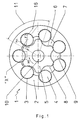
- Fig. 1 shows a Vernierungsrotorsatz 1 invention, consisting of a rotatable bearing ring 2 with bearing pockets 3, in which rotatably mounted planetary rotors 4 are arranged, which form an internal toothing, with an eccentrically mounted to the bearing ring 2 inner rotor 5 with approximately star-shaped outer contour, which is provided with an external toothing 6 is, wherein the external toothing 6 has a tooth less than the internal toothing.
- the toothed rotor set 1 has a suction region 7, a pressure region 8 and a displacement chamber 9.
- a drive torque M1 acts on the toothed inner rotor 5 via a drive shaft 10.
- a circumferential force F2 acts on the toothed planetary rotor 4, which is mounted in a bearing ring 2 (housing), from the toothed inner rotor 5.
- the circumferential force F2 is divided into two components, the impact force (radial force) F3 and the torque M4, both acting on the toothed planetary rotor.
- the impact force F3 acts through the center of the toothed planetary rotor 4, which is mounted in a bearing ring 2, and sets the bearing ring 2 in rotation.
- the toothed rotor set 1 according to the invention can be used as a pump for generating pressure by the inner rotor 5 is driven via a drive shaft 10.
- the toothed rotor set 1 according to the invention can also be used as a motor by the pressure area is pressurized, so that the inner rotor 5 is set in rotation and the drive shaft 10 drives.
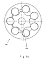
- Fig. 1a shows the Veriereungsrotorsatz 1 in a second working position. In this a maximum pressure is generated because the inner rotor 5 operates at most on the planetary rotors 4.
- Fig. 1b shows a plan view of the Veriereungsrotorsatz 1, wherein both a suction side 21 and a pressure side 23 are shown.
- the suction side 21 opens an inlet opening 22, which may be formed, for example, laterally as a bore in the toothed rotor set receiving housing.
- an outlet opening 24 opens into the pressure side 23.
- the diameter of the Auslrawöffung 24 is less than that of the inlet opening 22, since in the latter a higher flow rate is given.
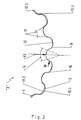
- Fig. 2 shows a variant I of the inventive toothing according to the detail "X" in Fig. 1 ,
- large impact force F3 radial force
- small circumferential force F4 must be transmitted.
- the tooth head 11 and the tooth root 12 are included in the rolling process, ie, the rolling of the toothed planetary rotor 4 on the toothed inner rotor curve.
- the surface portions of the teeth were chosen so that they correspond to the distribution of forces.
- the arcuate portion 14 of the toothing thus consists of the tooth base 12 and tooth tip 11, which transmit the impact force F3 between the toothed inner rotor 5 and the toothed planetary rotor 4.
- Only a small proportion of the toothed surfaces consists of sliding surfaces in the region of the tooth flanks 15, which convert the circumferential force F4 into a rotational movement of the toothed planetary rotor 4.
- the tooth head 11.1 of the toothed inner rotor 5 is calculated so that it applies exactly in the tooth root 12.2 of the toothed planetary rotor 4, and ensures trouble-free rolling.
- the tooth tip 11.2 of the toothed planetary rotor 4 engages in the tooth root 12.1 of the toothed inner rotor 5.
- Fig. 3 shows a second variant of the toothing according to the invention.
- the size of the flattening 13 depends on the field of application of the toothed rotor. At low speeds and high pressures a strong flattening 13 must be provided. At a high speed and low pressures, a moderate flattening 13 is sufficient to build up continuous lubricating film.
- a cycloid 20 was used, which favors the lubricating film structure more than a simple transition radius.
- Fig. 4 shows a third variant of the toothing according to the invention, wherein the tooth flanks 15 of the toothed inner rotor 5 and the toothed planetary rotors 4 are formed by an involute 18.
- the tooth tip of the planetary rotor 4 is formed as a cycloid 19. In this embodiment, however, there is a greater likelihood that engagement interference will occur.
- the stress on the contact line of the tooth flanks is calculated as the compressive stress of two parallel rollers which coincide with the tooth pairing in the following points: length b of the contact line, radius of curvature r1 and r2 in the cutting plane normal to the contact line, material pairing and surface quality. (rl and r2 are measured at the point of contact of the unloaded flanks)
- the toothing of the planetary rotor 4 is designed as zero toothing and that of the inner rotor 5 includes a negative profile displacement.
- pitch circle 2 t ⁇ 2 Pitch circle of the inner rotor curve 5
- Grobverzhnung Division t scope
- the inventive toothing can also be used in elliptical wheels, general non-circular wheels and Roots blowers.
Landscapes
- Engineering & Computer Science (AREA)
- Mechanical Engineering (AREA)
- General Engineering & Computer Science (AREA)
- Rotary Pumps (AREA)
- Details And Applications Of Rotary Liquid Pumps (AREA)
- Gears, Cams (AREA)
- Supercharger (AREA)
- Valve-Gear Or Valve Arrangements (AREA)
- Gear Transmission (AREA)
- Control Of Throttle Valves Provided In The Intake System Or In The Exhaust System (AREA)
Applications Claiming Priority (3)
| Application Number | Priority Date | Filing Date | Title |
|---|---|---|---|
| DE19922792 | 1999-05-18 | ||
| DE19922792A DE19922792A1 (de) | 1999-05-18 | 1999-05-18 | Verzahnungsrotorsatz |
| PCT/EP2000/004474 WO2000070228A1 (de) | 1999-05-18 | 2000-05-17 | Verzahnungsrotorsatz |
Publications (2)
| Publication Number | Publication Date |
|---|---|
| EP1180217A1 EP1180217A1 (de) | 2002-02-20 |
| EP1180217B1 true EP1180217B1 (de) | 2008-04-30 |
Family
ID=7908408
Family Applications (1)
| Application Number | Title | Priority Date | Filing Date |
|---|---|---|---|
| EP00941957A Expired - Lifetime EP1180217B1 (de) | 1999-05-18 | 2000-05-17 | Verzahnungsrotorsatz |
Country Status (11)
| Country | Link |
|---|---|
| US (1) | US6540637B2 (enExample) |
| EP (1) | EP1180217B1 (enExample) |
| JP (1) | JP3670215B2 (enExample) |
| CN (1) | CN1179129C (enExample) |
| AT (1) | ATE393881T1 (enExample) |
| AU (1) | AU5674300A (enExample) |
| BR (1) | BR0010627A (enExample) |
| CA (1) | CA2372883C (enExample) |
| DE (2) | DE19922792A1 (enExample) |
| MX (1) | MXPA01011453A (enExample) |
| WO (1) | WO2000070228A1 (enExample) |
Families Citing this family (30)
| Publication number | Priority date | Publication date | Assignee | Title |
|---|---|---|---|---|
| DE10010170A1 (de) | 2000-03-05 | 2001-09-06 | Gkn Sinter Metals Gmbh | Inverser Verzahnungsrotorsatz |
| US7438477B2 (en) | 2001-11-29 | 2008-10-21 | Ntn Corporation | Bearing part, heat treatment method thereof, and rolling bearing |
| CN101109414B (zh) * | 2003-02-28 | 2010-11-24 | Ntn株式会社 | 传动零件、制造传动零件的方法和圆锥滚子轴承 |
| JP4718781B2 (ja) | 2003-02-28 | 2011-07-06 | Ntn株式会社 | トランスミッションの構成部品および円錐ころ軸受 |
| JP2004301321A (ja) | 2003-03-14 | 2004-10-28 | Ntn Corp | オルタネータ用軸受およびプーリ用軸受 |
| DE10331979A1 (de) * | 2003-07-14 | 2005-02-17 | Gkn Sinter Metals Gmbh | Pumpe mit optimiertem Axialspiel |
| JP4557514B2 (ja) * | 2003-07-15 | 2010-10-06 | 住友電工焼結合金株式会社 | 内接歯車式ポンプ及びそのポンプのインナーロータ |
| DE10338212A1 (de) * | 2003-08-20 | 2005-03-10 | Zahnradfabrik Friedrichshafen | Volumenstromvariable Rotorpumpe |
| JP4152283B2 (ja) | 2003-08-29 | 2008-09-17 | Ntn株式会社 | 軸受部品の熱処理方法 |
| DE10349030B4 (de) * | 2003-10-13 | 2005-10-20 | Gkn Driveline Int Gmbh | Axialverstellvorrichtung |
| DE10350632A1 (de) * | 2003-10-29 | 2005-06-16 | Gkn Sinter Metals Gmbh | Doppel- oder Mehrfachpumpe |
| EP1707831B1 (en) | 2004-01-09 | 2012-02-01 | NTN Corporation | Thrust needle roller bearing, support structure receiving thrust load of compressor for car air-conditioner, support structure receiving thrust load of automatic transmission, support structure for nonstep variable speed gear, and support structure receiving thrust load of manual transmission |
| JP4540351B2 (ja) | 2004-01-15 | 2010-09-08 | Ntn株式会社 | 鋼の熱処理方法および軸受部品の製造方法 |
| DE102004047817B3 (de) * | 2004-09-29 | 2005-12-08 | Gkn Sinter Metals Gmbh | Nockenwellenversteller für eine Verbrennungskraftmaschine |
| BE1016298A4 (nl) * | 2004-11-04 | 2006-07-04 | Wiele Michel Van De Nv | Aandrijftandwiel voor het aandrijven van een grijperstang in een weefmachine. |
| DE102005021945B3 (de) * | 2005-05-12 | 2007-02-01 | Gkn Driveline International Gmbh | Hydrostatische Sperrkupplung |
| JP2007046717A (ja) | 2005-08-10 | 2007-02-22 | Ntn Corp | ジョイント用爪付き転動軸 |
| US7914084B2 (en) * | 2006-02-02 | 2011-03-29 | White Drive Products, Inc. | Control component for hydraulic circuit including spring applied-hydraulically released brake |
| FR2900988B1 (fr) * | 2006-05-12 | 2010-01-01 | Groupement Coeur Artificiel Total Carpentier Matra Carmat | Pompe volumetrique rotative a encombrement radial reduit |
| DE102006022472B3 (de) * | 2006-05-13 | 2008-02-07 | Gkn Driveline International Gmbh | Hydrostatische Kupplungsanordnung mit Zahnringmaschine |
| US7481633B2 (en) * | 2006-06-15 | 2009-01-27 | White Drive Products, Inc. | Rotor with cut-outs |
| US7670122B2 (en) * | 2006-08-15 | 2010-03-02 | Arvinmeritor Technology, Llc | Gerotor pump |
| CN101608617B (zh) * | 2008-06-20 | 2012-07-25 | 安徽理工大学 | 一种内啮合低脉动齿轮泵 |
| AT507284A1 (de) | 2008-09-05 | 2010-03-15 | Pkt Praez Skunststofftechnik B | Rotorensatz für eine rotorpumpe und rotorpumpe |
| CN101818782B (zh) * | 2010-03-08 | 2012-10-03 | 北京邮电大学 | 结构改进的摆线针轮行星减速器 |
| DE112012002458A5 (de) | 2011-06-14 | 2014-02-27 | Schaeffler Technologies Gmbh & Co. Kg | Hydrotransformator |
| US8678795B2 (en) * | 2011-07-29 | 2014-03-25 | White Drive Products, Inc. | Stator of a gerotor device and a method for manufacturing roller pockets in a stator of a gerotor device |
| CN102494103B (zh) * | 2011-11-24 | 2013-11-20 | 镇江大力液压马达股份有限公司 | 均匀接触一齿差摆线针轮副 |
| RU2015136203A (ru) * | 2015-08-14 | 2017-02-20 | Анатолий Степанович Токарь | Двухстороннее цевочно-циклоидальное зацепление двух колес и механизм с зубчатыми колесами |
| RU2673574C1 (ru) * | 2017-06-21 | 2018-11-28 | Анатолий Степанович Токарь | Трохоидальное зубчатое зацепление |
Family Cites Families (4)
| Publication number | Priority date | Publication date | Assignee | Title |
|---|---|---|---|---|
| US3917437A (en) * | 1974-03-18 | 1975-11-04 | Edwin A Link | Seal for a rotary piston device |
| SU819449A1 (ru) * | 1974-11-15 | 1981-04-07 | Кировоградский Ордена "Знак Почета"Завод Тракторных Гидроагрегатовим.Хху Съезда Кпсс | Шестеренный механизм дл машин сжидКОСТНОй или гАзООбРАзНОй РАбОчЕйСРЕдОй |
| DE4311166C2 (de) * | 1993-04-05 | 1995-01-12 | Danfoss As | Hydraulische Maschine |
| DE19646359C2 (de) * | 1996-11-09 | 2001-12-06 | Gkn Sinter Metals Gmbh | Schmierölpumpe mit einem Verzahnungsrotorsatz |
-
1999
- 1999-05-18 DE DE19922792A patent/DE19922792A1/de not_active Withdrawn
-
2000
- 2000-05-17 CN CNB008076871A patent/CN1179129C/zh not_active Expired - Lifetime
- 2000-05-17 AT AT00941957T patent/ATE393881T1/de not_active IP Right Cessation
- 2000-05-17 DE DE50015136T patent/DE50015136D1/de not_active Expired - Lifetime
- 2000-05-17 EP EP00941957A patent/EP1180217B1/de not_active Expired - Lifetime
- 2000-05-17 MX MXPA01011453A patent/MXPA01011453A/es active IP Right Grant
- 2000-05-17 BR BR0010627-5A patent/BR0010627A/pt not_active IP Right Cessation
- 2000-05-17 AU AU56743/00A patent/AU5674300A/en not_active Abandoned
- 2000-05-17 WO PCT/EP2000/004474 patent/WO2000070228A1/de not_active Ceased
- 2000-05-17 CA CA002372883A patent/CA2372883C/en not_active Expired - Fee Related
- 2000-05-17 JP JP2000618621A patent/JP3670215B2/ja not_active Expired - Fee Related
-
2001
- 2001-11-19 US US10/053,927 patent/US6540637B2/en not_active Expired - Lifetime
Also Published As
| Publication number | Publication date |
|---|---|
| CN1179129C (zh) | 2004-12-08 |
| EP1180217A1 (de) | 2002-02-20 |
| JP2002544442A (ja) | 2002-12-24 |
| JP3670215B2 (ja) | 2005-07-13 |
| CN1351694A (zh) | 2002-05-29 |
| US20020159905A1 (en) | 2002-10-31 |
| WO2000070228A1 (de) | 2000-11-23 |
| BR0010627A (pt) | 2002-02-19 |
| CA2372883C (en) | 2009-09-15 |
| MXPA01011453A (es) | 2002-11-07 |
| ATE393881T1 (de) | 2008-05-15 |
| DE19922792A1 (de) | 2000-11-23 |
| DE50015136D1 (de) | 2008-06-12 |
| CA2372883A1 (en) | 2000-11-23 |
| US6540637B2 (en) | 2003-04-01 |
| AU5674300A (en) | 2000-12-05 |
Similar Documents
| Publication | Publication Date | Title |
|---|---|---|
| EP1180217B1 (de) | Verzahnungsrotorsatz | |
| EP1340912B1 (de) | Zahnringmaschine mit Zahnlaufspiel | |
| EP0552443B1 (de) | Zahnradmaschine | |
| DE69511870T2 (de) | Schrägverzahnte zahnradpumpe oder-motor | |
| EP1340913B1 (de) | Zahnradmaschine | |
| EP0043899A1 (de) | Zahnringpumpe | |
| EP1261806B1 (de) | Inverser verzahnungsrotorsatz | |
| EP0433576B1 (de) | Zahnringpumpe für Verbrennungsmotoren und automatische Getriebe | |
| EP3384159B1 (de) | Aussenzahnradpumpe | |
| DE2758376A1 (de) | Kolbenkraft- oder -arbeitsmaschine mit innenlaeuferzahnradoelpumpe | |
| DE19646359C2 (de) | Schmierölpumpe mit einem Verzahnungsrotorsatz | |
| EP1685328B1 (de) | Doppel- oder mehrfachpumpe | |
| EP1328730B1 (de) | Füllstücklose innenzahnradpumpe | |
| DE102016207093B4 (de) | Zahnradfluidmaschine | |
| EP0846861B1 (de) | Stufenlos verstellbare Zahnringpumpe | |
| EP0607497B1 (de) | Sichellose Innenzahnradpumpe mit in die Zahnköpfe eingesetzten Dichtelementen | |
| DE3402710A1 (de) | Hydraulische kreiskolbenmaschine | |
| DE4428384A1 (de) | Zahnradpumpe | |
| DE4440782C5 (de) | Innenzahnradpumpe mit Verdrängervorsprüngen | |
| DE202014006761U1 (de) | Hydrostatische Kreiskolbenmaschine nach dem Orbitprinzip | |
| EP1182349A2 (de) | Zahnpumpe mit Schrägverzahnung | |
| DE102006021815A1 (de) | Hydraulische Zahnradmaschine | |
| DE102010038284A1 (de) | Innenzahnradpumpe | |
| DE10350631A1 (de) | Doppelpumpe | |
| WO2024194170A1 (de) | Fluidmaschine |
Legal Events
| Date | Code | Title | Description |
|---|---|---|---|
| PUAI | Public reference made under article 153(3) epc to a published international application that has entered the european phase |
Free format text: ORIGINAL CODE: 0009012 |
|
| 17P | Request for examination filed |
Effective date: 20011011 |
|
| AK | Designated contracting states |
Kind code of ref document: A1 Designated state(s): AT BE CH CY DE DK ES FI FR GB GR IE IT LI LU MC NL PT SE |
|
| AX | Request for extension of the european patent |
Free format text: MK;RO;SI |
|
| 17Q | First examination report despatched |
Effective date: 20040210 |
|
| GRAP | Despatch of communication of intention to grant a patent |
Free format text: ORIGINAL CODE: EPIDOSNIGR1 |
|
| GRAS | Grant fee paid |
Free format text: ORIGINAL CODE: EPIDOSNIGR3 |
|
| GRAA | (expected) grant |
Free format text: ORIGINAL CODE: 0009210 |
|
| AK | Designated contracting states |
Kind code of ref document: B1 Designated state(s): AT BE CH CY DE DK ES FI FR GB GR IE IT LI LU MC NL PT SE |
|
| REG | Reference to a national code |
Ref country code: GB Ref legal event code: FG4D Free format text: NOT ENGLISH |
|
| REG | Reference to a national code |
Ref country code: CH Ref legal event code: EP |
|
| REG | Reference to a national code |
Ref country code: IE Ref legal event code: FG4D Free format text: LANGUAGE OF EP DOCUMENT: GERMAN |
|
| REF | Corresponds to: |
Ref document number: 50015136 Country of ref document: DE Date of ref document: 20080612 Kind code of ref document: P |
|
| NLV1 | Nl: lapsed or annulled due to failure to fulfill the requirements of art. 29p and 29m of the patents act | ||
| PG25 | Lapsed in a contracting state [announced via postgrant information from national office to epo] |
Ref country code: PT Free format text: LAPSE BECAUSE OF FAILURE TO SUBMIT A TRANSLATION OF THE DESCRIPTION OR TO PAY THE FEE WITHIN THE PRESCRIBED TIME-LIMIT Effective date: 20080930 Ref country code: NL Free format text: LAPSE BECAUSE OF FAILURE TO SUBMIT A TRANSLATION OF THE DESCRIPTION OR TO PAY THE FEE WITHIN THE PRESCRIBED TIME-LIMIT Effective date: 20080430 Ref country code: ES Free format text: LAPSE BECAUSE OF FAILURE TO SUBMIT A TRANSLATION OF THE DESCRIPTION OR TO PAY THE FEE WITHIN THE PRESCRIBED TIME-LIMIT Effective date: 20080810 Ref country code: FI Free format text: LAPSE BECAUSE OF FAILURE TO SUBMIT A TRANSLATION OF THE DESCRIPTION OR TO PAY THE FEE WITHIN THE PRESCRIBED TIME-LIMIT Effective date: 20080430 |
|
| BERE | Be: lapsed |
Owner name: GKN SINTER METALS G.M.B.H. Effective date: 20080531 |
|
| REG | Reference to a national code |
Ref country code: IE Ref legal event code: FD4D |
|
| PG25 | Lapsed in a contracting state [announced via postgrant information from national office to epo] |
Ref country code: MC Free format text: LAPSE BECAUSE OF NON-PAYMENT OF DUE FEES Effective date: 20080531 |
|
| REG | Reference to a national code |
Ref country code: CH Ref legal event code: PL |
|
| PG25 | Lapsed in a contracting state [announced via postgrant information from national office to epo] |
Ref country code: SE Free format text: LAPSE BECAUSE OF FAILURE TO SUBMIT A TRANSLATION OF THE DESCRIPTION OR TO PAY THE FEE WITHIN THE PRESCRIBED TIME-LIMIT Effective date: 20080731 Ref country code: LI Free format text: LAPSE BECAUSE OF NON-PAYMENT OF DUE FEES Effective date: 20080531 Ref country code: IE Free format text: LAPSE BECAUSE OF FAILURE TO SUBMIT A TRANSLATION OF THE DESCRIPTION OR TO PAY THE FEE WITHIN THE PRESCRIBED TIME-LIMIT Effective date: 20080430 Ref country code: DK Free format text: LAPSE BECAUSE OF FAILURE TO SUBMIT A TRANSLATION OF THE DESCRIPTION OR TO PAY THE FEE WITHIN THE PRESCRIBED TIME-LIMIT Effective date: 20080430 Ref country code: CH Free format text: LAPSE BECAUSE OF NON-PAYMENT OF DUE FEES Effective date: 20080531 |
|
| ET | Fr: translation filed | ||
| PLBE | No opposition filed within time limit |
Free format text: ORIGINAL CODE: 0009261 |
|
| STAA | Information on the status of an ep patent application or granted ep patent |
Free format text: STATUS: NO OPPOSITION FILED WITHIN TIME LIMIT |
|
| PG25 | Lapsed in a contracting state [announced via postgrant information from national office to epo] |
Ref country code: BE Free format text: LAPSE BECAUSE OF NON-PAYMENT OF DUE FEES Effective date: 20080531 |
|
| 26N | No opposition filed |
Effective date: 20090202 |
|
| PG25 | Lapsed in a contracting state [announced via postgrant information from national office to epo] |
Ref country code: AT Free format text: LAPSE BECAUSE OF NON-PAYMENT OF DUE FEES Effective date: 20080517 |
|
| PG25 | Lapsed in a contracting state [announced via postgrant information from national office to epo] |
Ref country code: LU Free format text: LAPSE BECAUSE OF NON-PAYMENT OF DUE FEES Effective date: 20080517 Ref country code: CY Free format text: LAPSE BECAUSE OF FAILURE TO SUBMIT A TRANSLATION OF THE DESCRIPTION OR TO PAY THE FEE WITHIN THE PRESCRIBED TIME-LIMIT Effective date: 20080430 |
|
| PG25 | Lapsed in a contracting state [announced via postgrant information from national office to epo] |
Ref country code: GR Free format text: LAPSE BECAUSE OF FAILURE TO SUBMIT A TRANSLATION OF THE DESCRIPTION OR TO PAY THE FEE WITHIN THE PRESCRIBED TIME-LIMIT Effective date: 20080731 |
|
| PGFP | Annual fee paid to national office [announced via postgrant information from national office to epo] |
Ref country code: GB Payment date: 20110523 Year of fee payment: 12 |
|
| GBPC | Gb: european patent ceased through non-payment of renewal fee |
Effective date: 20120517 |
|
| PG25 | Lapsed in a contracting state [announced via postgrant information from national office to epo] |
Ref country code: GB Free format text: LAPSE BECAUSE OF NON-PAYMENT OF DUE FEES Effective date: 20120517 |
|
| REG | Reference to a national code |
Ref country code: DE Ref legal event code: R082 Ref document number: 50015136 Country of ref document: DE Representative=s name: VON KREISLER SELTING WERNER - PARTNERSCHAFT VO, DE Ref country code: DE Ref legal event code: R082 Ref document number: 50015136 Country of ref document: DE Representative=s name: KNH PATENTANWAELTE KAHLHOEFER NEUMANN ROESSLER, DE Ref country code: DE Ref legal event code: R082 Ref document number: 50015136 Country of ref document: DE Representative=s name: KAHLHOEFER ROESSLER KREUELS PATENTANWAELTE PAR, DE |
|
| REG | Reference to a national code |
Ref country code: DE Ref legal event code: R082 Ref document number: 50015136 Country of ref document: DE Representative=s name: KARO IP PATENTANWAELTE KAHLHOEFER ROESSLER KRE, DE Ref country code: DE Ref legal event code: R082 Ref document number: 50015136 Country of ref document: DE Representative=s name: KNH PATENTANWAELTE KAHLHOEFER NEUMANN ROESSLER, DE Ref country code: DE Ref legal event code: R082 Ref document number: 50015136 Country of ref document: DE Representative=s name: KAHLHOEFER ROESSLER KREUELS PATENTANWAELTE PAR, DE |
|
| REG | Reference to a national code |
Ref country code: FR Ref legal event code: PLFP Year of fee payment: 17 |
|
| REG | Reference to a national code |
Ref country code: FR Ref legal event code: PLFP Year of fee payment: 18 |
|
| REG | Reference to a national code |
Ref country code: DE Ref legal event code: R082 Ref document number: 50015136 Country of ref document: DE Representative=s name: KARO IP PATENTANWAELTE KAHLHOEFER ROESSLER KRE, DE Ref country code: DE Ref legal event code: R082 Ref document number: 50015136 Country of ref document: DE Representative=s name: KAHLHOEFER ROESSLER KREUELS PATENTANWAELTE PAR, DE |
|
| REG | Reference to a national code |
Ref country code: FR Ref legal event code: PLFP Year of fee payment: 19 |
|
| PGFP | Annual fee paid to national office [announced via postgrant information from national office to epo] |
Ref country code: DE Payment date: 20190522 Year of fee payment: 20 Ref country code: IT Payment date: 20190521 Year of fee payment: 20 |
|
| PGFP | Annual fee paid to national office [announced via postgrant information from national office to epo] |
Ref country code: FR Payment date: 20190521 Year of fee payment: 20 |
|
| REG | Reference to a national code |
Ref country code: DE Ref legal event code: R082 Ref document number: 50015136 Country of ref document: DE Representative=s name: KARO IP PATENTANWAELTE KAHLHOEFER ROESSLER KRE, DE |
|
| REG | Reference to a national code |
Ref country code: DE Ref legal event code: R071 Ref document number: 50015136 Country of ref document: DE |
|
| P01 | Opt-out of the competence of the unified patent court (upc) registered |
Effective date: 20230602 |