EP1180217B1 - Toothed rotor set - Google Patents
Toothed rotor set Download PDFInfo
- Publication number
- EP1180217B1 EP1180217B1 EP00941957A EP00941957A EP1180217B1 EP 1180217 B1 EP1180217 B1 EP 1180217B1 EP 00941957 A EP00941957 A EP 00941957A EP 00941957 A EP00941957 A EP 00941957A EP 1180217 B1 EP1180217 B1 EP 1180217B1
- Authority
- EP
- European Patent Office
- Prior art keywords
- tooth
- rotor
- toothed
- teeth
- planetary
- Prior art date
- Legal status (The legal status is an assumption and is not a legal conclusion. Google has not performed a legal analysis and makes no representation as to the accuracy of the status listed.)
- Expired - Lifetime
Links
- 238000005096 rolling process Methods 0.000 claims description 16
- 238000000034 method Methods 0.000 claims description 8
- 238000004512 die casting Methods 0.000 claims description 4
- 239000012530 fluid Substances 0.000 claims description 4
- 238000004519 manufacturing process Methods 0.000 claims description 4
- XAGFODPZIPBFFR-UHFFFAOYSA-N aluminium Chemical compound [Al] XAGFODPZIPBFFR-UHFFFAOYSA-N 0.000 claims description 2
- 229910052782 aluminium Inorganic materials 0.000 claims description 2
- 230000001419 dependent effect Effects 0.000 claims description 2
- 238000001125 extrusion Methods 0.000 claims description 2
- 238000001746 injection moulding Methods 0.000 claims description 2
- 239000000463 material Substances 0.000 claims description 2
- 239000004411 aluminium Substances 0.000 claims 1
- 238000010310 metallurgical process Methods 0.000 claims 1
- 238000007493 shaping process Methods 0.000 claims 1
- 239000010687 lubricating oil Substances 0.000 abstract description 4
- 238000002485 combustion reaction Methods 0.000 abstract description 3
- 230000005540 biological transmission Effects 0.000 description 12
- 230000001050 lubricating effect Effects 0.000 description 10
- 238000006073 displacement reaction Methods 0.000 description 5
- 230000002093 peripheral effect Effects 0.000 description 4
- 230000007704 transition Effects 0.000 description 4
- 238000007789 sealing Methods 0.000 description 3
- 230000006378 damage Effects 0.000 description 2
- 239000003921 oil Substances 0.000 description 2
- 238000004381 surface treatment Methods 0.000 description 2
- 230000002411 adverse Effects 0.000 description 1
- 238000004532 chromating Methods 0.000 description 1
- 238000010276 construction Methods 0.000 description 1
- 238000005520 cutting process Methods 0.000 description 1
- 230000007423 decrease Effects 0.000 description 1
- 238000009826 distribution Methods 0.000 description 1
- 230000000694 effects Effects 0.000 description 1
- 230000002349 favourable effect Effects 0.000 description 1
- 239000000945 filler Substances 0.000 description 1
- 239000000314 lubricant Substances 0.000 description 1
- 238000005461 lubrication Methods 0.000 description 1
- 238000000465 moulding Methods 0.000 description 1
- 238000006396 nitration reaction Methods 0.000 description 1
- 238000004663 powder metallurgy Methods 0.000 description 1
- 230000002028 premature Effects 0.000 description 1
- 239000007787 solid Substances 0.000 description 1
- 230000003068 static effect Effects 0.000 description 1
- 239000000126 substance Substances 0.000 description 1
- 238000013519 translation Methods 0.000 description 1
- 230000014616 translation Effects 0.000 description 1
Images


Classifications
-
- F—MECHANICAL ENGINEERING; LIGHTING; HEATING; WEAPONS; BLASTING
- F04—POSITIVE - DISPLACEMENT MACHINES FOR LIQUIDS; PUMPS FOR LIQUIDS OR ELASTIC FLUIDS
- F04C—ROTARY-PISTON, OR OSCILLATING-PISTON, POSITIVE-DISPLACEMENT MACHINES FOR LIQUIDS; ROTARY-PISTON, OR OSCILLATING-PISTON, POSITIVE-DISPLACEMENT PUMPS
- F04C2/00—Rotary-piston machines or pumps
- F04C2/08—Rotary-piston machines or pumps of intermeshing-engagement type, i.e. with engagement of co-operating members similar to that of toothed gearing
- F04C2/10—Rotary-piston machines or pumps of intermeshing-engagement type, i.e. with engagement of co-operating members similar to that of toothed gearing of internal-axis type with the outer member having more teeth or tooth-equivalents, e.g. rollers, than the inner member
Definitions
- the invention relates to a toothed rotor set for a pump, in particular for a lubricating oil pump for internal combustion engines.
- the toothed rotor is similar to a toothed ring pump with a toothed design, wherein the function and operation of a toothed rotor set, which corresponds to a gerotor pump.
- the pressure chamber is not separated from the suction chamber by a crescent-shaped filler, but a special design of the teeth - based on the trochoid toothing - ensures the seal between the toothed ring and externally toothed pinion.
- the internally toothed ring has one more tooth than the pinion, so that with appropriate design of the teeth, the tooth heads touch exactly opposite the tooth engagement point.
- the disadvantage of gerotor pumps is that internal leakage and thus poor volumetric efficiency occurs through this head clearance in the gerotor pumps. As a result, high pressures can not be built up at low speeds.
- the pump forms a generic Zahnahnungsrotorsatz consisting of an outer ring with an internal toothing and a gear externally recorded therein with external teeth, wherein the internal toothing is formed by rollers rotatably mounted in the outer ring and a tooth more than the outer toothing, wherein the outer toothing of the gear fine teeth superimposed with a much smaller module and each roller on its perimeter with a fine toothing has the same module, in which engage the teeth of the gear.
- the function of the toothed rotor set results from the fact that a drive torque acts on the inner rotor via a drive shaft and rotates the latter. From the toothed inner rotor, a force is transmitted to the planetary gear, on the one hand results in an impact force through the center of the planetary gear and a circumferential force, which causes a torque of the planetary gear. The impact force acting on the bearing ring causes it to rotate.
- a hydraulic machine which is formed of a rotatable bearing ring with bearing pockets, wherein in the bearing pockets rotatably mounted rollers are arranged with recesses on the peripheral surface, with an eccentrically mounted to the bearing ring inner rotor with approximately star-shaped outer contour, wherein the teeth of the star in the Recesses of the rollers engage.
- the rollers and the inner rotor do not have the fine toothing according to the invention, as a result of which engagement errors occur, in particular in gear tooth sets with a higher number of teeth, for example 11/12.
- the design can only be run with very small tolerances.
- a Veriereungsrotorsatz consisting of a rotatable bearing ring with bearing pockets in which rotatably mounted planetary rotors are arranged, which form an internal toothing, with an eccentrically mounted to the bearing ring inner rotor with approximately star-shaped outer contour, which is provided with an outer toothing the external toothing has one tooth less than the internal toothing and the toothing of at least one of the two rotor systems has an arcuate component at least in partial regions of the tooth form of the toothing.
- the advantage of such a designed Zahnahnungsrotorsatzes is that due to the arcuate portion of the tooth shape substantially rolling friction and no sliding friction occurs, so that the wear on the teeth is minimized.
- the tooth shape in the region of the tooth tip and / or the tooth root, is arcuate.
- Such a design of the tooth shape in the region of the tooth head and / or the tooth root makes it possible for very large impact forces (radial forces) to be transmitted, it being possible for the proportion of peripheral force to be transmitted to be small.
- the tooth head and the tooth root in contrast to the involute toothings known in the case of toothed rotors, are introduced into the rolling process, i. the rolling of the toothed planetary rotors on the toothed inner rotor curve, with included.
- the convexly curved tooth flank of the planetary rotor and the concavely curved tooth flank of the inner rotor form a relatively large sealing surface during tooth engagement, which seals the displacement chamber from the suction region into the pressure region when the displacement chamber passes. Even deviations of the squareness of the rotor do not lead to leakage of the displacement chamber.
- the region of the tooth tip and / or the tooth root has the tooth shape a flattening.
- the torque acts through the toothed inner rotor via the toothed planetary rotor on the bearing ring it comes, geometrically caused, almost to a stop of the planetary gear.
- the planetary rotor tooth heads were flattened. The size of the flattening depends on the field of application of the toothed rotor. At low speeds and high pressures, a strong flattening is necessary.
- the region of the tooth tip and / or the tooth root has the tooth shape a large radius of curvature.
- the flattening of the planetary rotor tooth heads also causes an improvement in the transmission of power (Hertzian pressure) from the planetary rotor to the bearing ring.
- the arcuate portion is at least partially formed as a cycloid.
- the cycloid has proven to be particularly advantageous in terms of roll-off and transfer of impact forces. This cycloid toothing ensures perfect sliding low rolling, even with considerable changes in curvature and small radii of curvature, which in turn reduces wear.
- the tooth form is formed as involute.
- the tooth flanks of the toothed inner rotor and the toothed planetary rotor are formed by an involute, but in this embodiment, engagement errors may occur more easily than in an embodiment whose tooth flanks are formed as cycloids.
- the toothing has a low-wear surface.
- the low-wear surface can be replaced by a chemical, in particular thermochemical and / or physical surface treatment can be achieved.
- the surface can also be galvanized. Further advantageous surface treatment methods are caburation and nitration and / or nitrocarburizing, boriding and / or chromating.
- At least one fluid channel is arranged in the region of the bearing pockets.
- the fluid channel may be connected to the pressure side of the pump so that lubricating oil is continuously supplied between the planetary rotor and the bearing pocket in order to ensure an improved lubricating film structure.
- all movable parts of the toothed rotor set in particular the bearing ring and / or the planetary rotors and / or the inner rotor on at least one end face on a circumferential ridge.
- This circumferential ridge serves as a seal within the housing in which the toothed rotor set is received.
- movable parts have a sealing surface on their end faces, which extends over the entire surface, with the exception of the teeth.
- the seal according to the invention by means of the circumferential ridge has the advantage that the high friction forces occurring in the known seals are greatly reduced and thus the toothed rotor set works lighter and thus more efficient.
- the circumferential ridge has a width which represents the optimum between sealing effect and frictional force.
- the invention relates to a method for producing a Verzahungsrotorsatzes, wherein this is in a molding process, preferably by means of powder metallurgy process, plastic injection molding, extrusion, die casting, especially aluminum die casting, and stamping process is prepared.
- a complex toothing as having the toothed rotor set according to the invention, is simple and inexpensive to produce by means of these methods.
- a filing and sawing which is known in the usual gears Can be used, can find no application in the invention, since the toothing is too complicated for this purpose.
- the toothed rotor set in a pump in particular a lubricating oil pump for internal combustion engines, is used.
- Veriereungsrotorsatz is used as a motor.
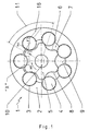
- Fig. 1 shows a Vernierungsrotorsatz 1 invention, consisting of a rotatable bearing ring 2 with bearing pockets 3, in which rotatably mounted planetary rotors 4 are arranged, which form an internal toothing, with an eccentrically mounted to the bearing ring 2 inner rotor 5 with approximately star-shaped outer contour, which is provided with an external toothing 6 is, wherein the external toothing 6 has a tooth less than the internal toothing.
- the toothed rotor set 1 has a suction region 7, a pressure region 8 and a displacement chamber 9.
- a drive torque M1 acts on the toothed inner rotor 5 via a drive shaft 10.
- a circumferential force F2 acts on the toothed planetary rotor 4, which is mounted in a bearing ring 2 (housing), from the toothed inner rotor 5.
- the circumferential force F2 is divided into two components, the impact force (radial force) F3 and the torque M4, both acting on the toothed planetary rotor.
- the impact force F3 acts through the center of the toothed planetary rotor 4, which is mounted in a bearing ring 2, and sets the bearing ring 2 in rotation.
- the toothed rotor set 1 according to the invention can be used as a pump for generating pressure by the inner rotor 5 is driven via a drive shaft 10.
- the toothed rotor set 1 according to the invention can also be used as a motor by the pressure area is pressurized, so that the inner rotor 5 is set in rotation and the drive shaft 10 drives.
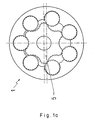
- Fig. 1a shows the Veriereungsrotorsatz 1 in a second working position. In this a maximum pressure is generated because the inner rotor 5 operates at most on the planetary rotors 4.
- Fig. 1b shows a plan view of the Veriereungsrotorsatz 1, wherein both a suction side 21 and a pressure side 23 are shown.
- the suction side 21 opens an inlet opening 22, which may be formed, for example, laterally as a bore in the toothed rotor set receiving housing.
- an outlet opening 24 opens into the pressure side 23.
- the diameter of the Auslrawöffung 24 is less than that of the inlet opening 22, since in the latter a higher flow rate is given.
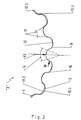
- Fig. 2 shows a variant I of the inventive toothing according to the detail "X" in Fig. 1 ,
- large impact force F3 radial force
- small circumferential force F4 must be transmitted.
- the tooth head 11 and the tooth root 12 are included in the rolling process, ie, the rolling of the toothed planetary rotor 4 on the toothed inner rotor curve.
- the surface portions of the teeth were chosen so that they correspond to the distribution of forces.
- the arcuate portion 14 of the toothing thus consists of the tooth base 12 and tooth tip 11, which transmit the impact force F3 between the toothed inner rotor 5 and the toothed planetary rotor 4.
- Only a small proportion of the toothed surfaces consists of sliding surfaces in the region of the tooth flanks 15, which convert the circumferential force F4 into a rotational movement of the toothed planetary rotor 4.
- the tooth head 11.1 of the toothed inner rotor 5 is calculated so that it applies exactly in the tooth root 12.2 of the toothed planetary rotor 4, and ensures trouble-free rolling.
- the tooth tip 11.2 of the toothed planetary rotor 4 engages in the tooth root 12.1 of the toothed inner rotor 5.
- Fig. 3 shows a second variant of the toothing according to the invention.
- the size of the flattening 13 depends on the field of application of the toothed rotor. At low speeds and high pressures a strong flattening 13 must be provided. At a high speed and low pressures, a moderate flattening 13 is sufficient to build up continuous lubricating film.
- a cycloid 20 was used, which favors the lubricating film structure more than a simple transition radius.
- Fig. 4 shows a third variant of the toothing according to the invention, wherein the tooth flanks 15 of the toothed inner rotor 5 and the toothed planetary rotors 4 are formed by an involute 18.
- the tooth tip of the planetary rotor 4 is formed as a cycloid 19. In this embodiment, however, there is a greater likelihood that engagement interference will occur.
- the stress on the contact line of the tooth flanks is calculated as the compressive stress of two parallel rollers which coincide with the tooth pairing in the following points: length b of the contact line, radius of curvature r1 and r2 in the cutting plane normal to the contact line, material pairing and surface quality. (rl and r2 are measured at the point of contact of the unloaded flanks)
- the toothing of the planetary rotor 4 is designed as zero toothing and that of the inner rotor 5 includes a negative profile displacement.
- pitch circle 2 t ⁇ 2 Pitch circle of the inner rotor curve 5
- Grobverzhnung Division t scope
- the inventive toothing can also be used in elliptical wheels, general non-circular wheels and Roots blowers.
Abstract
Description
Die Erfindung betrifft einen Verzahnungsrotorsatz für eine Pumpe, insbesondere für eine Schmierölpumpe für Verbrennungsmotoren. Der Verzahnungsrotor ist ähnlich einer Zahnringpumpe mit verzahnter Ausführung, wobei die Funktion und Wirkungsweise eines Verzahnungsrotorsatzes, der einer Zahnringpumpe entspricht.The invention relates to a toothed rotor set for a pump, in particular for a lubricating oil pump for internal combustion engines. The toothed rotor is similar to a toothed ring pump with a toothed design, wherein the function and operation of a toothed rotor set, which corresponds to a gerotor pump.
Bei Zahnringpumpen wird der Druckraum vom Saugraum nicht durch ein sichelförmiges Füllstück getrennt, sondern eine besondere Ausbildung der Zähne - basierend auf der Trochoiden-Verzahnung - gewährleistet die Abdichtung zwischen Zahnring und außenverzahntem Ritzel. Der innenverzahnte Zahnring besitzt einen Zahn mehr als das Ritzel, so daß bei entsprechender Gestaltung der Zähne sich die Zahnköpfe genau gegenüber dem Zahneingriffspunkt berühren. Damit ein Abrollen gewährleistet ist, muß zwischen dem Zahnkopf des Außenläufers und dem Zahnkopf des Innenläufers ein Kopfspiel vorhanden sein. Der Nachteil von Zahnringpumpen ist, daß durch dieses Kopfspiel bei den Zahnringpumpen innere Leckagen und somit ein schlechter volumetrischer Wirkungsgrad auftritt. Hierdurch können bei niedrigen Drehzahlen keine hohen Drücke aufgebaut werden.In gerotor pumps, the pressure chamber is not separated from the suction chamber by a crescent-shaped filler, but a special design of the teeth - based on the trochoid toothing - ensures the seal between the toothed ring and externally toothed pinion. The internally toothed ring has one more tooth than the pinion, so that with appropriate design of the teeth, the tooth heads touch exactly opposite the tooth engagement point. In order to ensure unwinding, there must be head play between the tooth head of the outer rotor and the tooth head of the inner rotor. The disadvantage of gerotor pumps is that internal leakage and thus poor volumetric efficiency occurs through this head clearance in the gerotor pumps. As a result, high pressures can not be built up at low speeds.
Vorteilhafter im Vergleich zu Zahnringpumpen ist ein Pumpe nach der Lehre der
Die Funktion des Verzahnungsrotorsatzes ergibt sich dadurch, daß ein Antriebsmoment über eine Antriebswelle auf den Innenrotor wirkt und diesen dreht. Vom verzahnten Innenrotor wird eine Kraft auf das Planetenrad übertragen, die einerseits eine Stoßkraft durch das Zentrum des Planetenrades und eine Umfangskraft ergibt, die ein Drehmoment des Planetenrades bewirkt. Durch die Stoßkraft, die auf den Lagerring wirkt, wird dieser in Rotation versetzt.The function of the toothed rotor set results from the fact that a drive torque acts on the inner rotor via a drive shaft and rotates the latter. From the toothed inner rotor, a force is transmitted to the planetary gear, on the one hand results in an impact force through the center of the planetary gear and a circumferential force, which causes a torque of the planetary gear. The impact force acting on the bearing ring causes it to rotate.
Die auftretenden Kräfte und Momente können bei dem gattungsgemäßen Verzahnungsrotorsatz nicht optimal durch die bisher verwendete Evolventenverzahnung aufgenommen werden. Insbesondere besteht das Problem, daß die bekannte Verzahnung die Stoß- und Umfangskräfte nicht ohne große Flächenpressung in Form einer Linienberührung überträgt. Die bisher bekannten Verzahnungen eignen sich nur für die Übertragung hoher Umfangskräfte und nicht für die Übertragung großer Stoßkräfte, die durch das Zentrum des Planetenrades verlaufen.The occurring forces and moments can not be optimally absorbed by the previously used involute toothing in the generic Zahnahnungsrotorsatz. In particular, there is the problem that the known toothing does not transmit the impact and peripheral forces without large surface pressure in the form of a line contact. The previously known gears are only suitable for the transmission of high circumferential forces and not for the transmission of large impact forces that pass through the center of the planetary gear.
Als nachteilig erweist sich der gattungsbildende Verzahnungsrotorsatz dahingehend, daß nicht unter allen Betriebsbedingungen ein sauberes Abrollen ohne Eingriffsstörungen gewährleistet ist. Die Bewegung der Planetenräder relativ zum Lagering kommt in einer Position zum Stillstand.A disadvantage of the generic type Zahnahnungsrotorsatz proves that not under all operating conditions a clean rolling is ensured without interference interference. The movement of the planet gears relative to the bearing comes to a halt in one position.
In diesem Zustand, in dem das Planetenrad nahezu stillsteht und gleichzeitig eine große Kraft übertragen wird, besteht die Gefahr, daß der Schmierfilm zwischen Planetenzahnkopf und Außenrotor zusammenbricht, wodurch die Couetteströmung zum Stillstand kommt. Hierbei entsteht Festkörperkontakt durch den Verlust des Schmiermediums im Spalt. Es besteht somit nicht mehr eine günstige hydrodynamische Schmierung sondern es entstehen Mischreibungszustände und im ungünstigsten Fall Haftreibung. Im Falle der Misch- und Haftreibung treten Verschleißerscheinungen auf und die Standzeit des Verzahnungsrotorsatzes sinkt.In this state, in which the planetary gear almost stops and at the same time a large force is transmitted, there is a risk that the lubricating film between the planetary gear head and outer rotor collapses, whereby the Couetteströmung comes to a standstill. This creates solid state contact by the loss of the lubricant in the gap. There is thus no longer a favorable hydrodynamic lubrication but it creates mixed friction conditions and in the worst case stiction. In the case of mixed and static friction wear occurs and the service life of the gear rotor set decreases.
Aus der
Aus den Nachteilen des bekannten Standes der Technik ergibt sich die Aufgabe einen Verzahnungsrotorsatz zu bilden, der so gestaltet ist, daß ein dauerhafter Schmierfilmaufbau zur Vermeidung ungünstiger Reibungszustände gewährleistet ist, wobei der Verzahnungsrotorsatz die auftretenden Kräfte und Momente sicher übertragen muß.From the disadvantages of the known prior art, the task results to form a Verzahnungsrotorsatz, which is designed so that a permanent lubricating film construction to avoid adverse frictional conditions is ensured, the Verzahnungsrotorsatz must transmit the forces and moments occurring safely.
Die Aufgabe wird erfindungsgemäß gelöst durch einen Verzahnungsrotorsatz, bestehend aus einem drehbaren Lagerring mit Lagertaschen, in denen drehbar gelagerte Planetenrotoren angeordnet sind, die eine Innenverzahnung bilden, mit einem exzentrisch zum Lagerring gelagerten Innenrotor mit annähernd sternförmiger Außenkontur, die mit einer Außenverzahnung versehen ist, wobei die Außenverzahnung einen Zahn weniger aufweist als die Innenverzahnung und die Verzahnung wenigstens eines der beiden Rotorensysteme zumindest in Teilbereichen der Zahnform der Verzahnung einen bogenförmigen Anteil aufweist. Der Vorteil eines derart gestalteten Verzahnungsrotorsatzes besteht darin, daß durch den bogenförmigen Anteil an der Zahnform im wesentlichen Rollreibung und keine Gleitreibung auftritt, so daß der Verschleiß an der Verzahnung minimiert wird. Durch den konvex ausgebildeten Zahnkopf des verzahnten Innenrotors und den konkav ausgebildeten Zahnfuß des verzahnten Planetenrotors kommt es zu einer Berührungsfläche und nicht zu einer Berührungslinie. Die Hertzsche Pressung wird durch diese Wälzpaarung sehr stark reduziert.The object is achieved by a Verzahnungsrotorsatz consisting of a rotatable bearing ring with bearing pockets in which rotatably mounted planetary rotors are arranged, which form an internal toothing, with an eccentrically mounted to the bearing ring inner rotor with approximately star-shaped outer contour, which is provided with an outer toothing the external toothing has one tooth less than the internal toothing and the toothing of at least one of the two rotor systems has an arcuate component at least in partial regions of the tooth form of the toothing. The advantage of such a designed Zahnahnungsrotorsatzes is that due to the arcuate portion of the tooth shape substantially rolling friction and no sliding friction occurs, so that the wear on the teeth is minimized. Due to the convex tooth head of the toothed inner rotor and the concave tooth root of the toothed planetary rotor, there is a contact surface and not to a contact line. The Hertzian pressure is greatly reduced by this Wälzpaarung.
Dies gilt auch für die Zahnflanken des verzahnten Innenrotors und des verzahnten Planetenrades. Durch Einbeziehen eines Flankenspiels zwischen dem Zahn des Planetenrotors und der Zahnlücke des Innenrotors ist gewährleistet, daß die großen Stoßkräfte nur über Zahnkopf und Zahnfuß übertragen werden. Dadurch wird verhindert, daß auf die Zahnflanken große Keilkräfte wirken, die zur Zerstörung der Flankenoberflächen führen können. Zusätzlich kann durch das Flankenspiel das Fördermedium aus den Zahnlücken abfließen, da es sonst zu Quetschöl kommt, was zu sehr hohen Druckaufbau führen kann.This also applies to the tooth flanks of the toothed inner rotor and the toothed planetary gear. By including a backlash between the tooth of the planetary rotor and the tooth gap of the inner rotor ensures that the large impact forces are transmitted only over the tooth head and tooth root. This prevents that act on the tooth flanks large wedge forces that can lead to the destruction of the flank surfaces. In addition, by the backlash the fluid drain from the tooth gaps, otherwise it comes to squeezing oil, which can lead to very high pressure build-up.
In vorteilhafter Ausgestaltung der Erfindung ist vorgesehen, daß im Bereich des Zahnkopfes und/oder des Zahnfußes die Zahnform bogenförmig ausgebildet ist. Eine Derartige Gestaltung der Zahnform im Bereich des Zahnkopfes und/oder des Zahnfußes ermöglicht es, daß sehr große Stoßkräfte (Radialkräfte) übertragen werden können, wobei der Anteil der zu übertragenden Umfangskraft gering sein kann. Es werden hierbei der Zahnkopf und der Zahnfuß, im Gegensatz zu den bei Verzahnungsrotoren bekannten Evolventenverzahnungen in den Abrollvorgang, d.h. dem Abwälzen der verzahnten Planetenrotoren auf der verzahnten Innenrotorkurve, mit einbezogen.In an advantageous embodiment of the invention it is provided that in the region of the tooth tip and / or the tooth root, the tooth shape is arcuate. Such a design of the tooth shape in the region of the tooth head and / or the tooth root makes it possible for very large impact forces (radial forces) to be transmitted, it being possible for the proportion of peripheral force to be transmitted to be small. In this case, the tooth head and the tooth root, in contrast to the involute toothings known in the case of toothed rotors, are introduced into the rolling process, i. the rolling of the toothed planetary rotors on the toothed inner rotor curve, with included.
Die konvex gekrümmte Zahnflanke des Planetenrotors und die konkav gekrümmte Zahnflanke des Innenrotors bilden beim Zahneingriff eine relativ große Dichtfläche, die beim Übertritt der Verdrängerkammer vom Saugbereich in den Druckbereich die Verdrängerkammer abdichtet. Auch Abweichungen der Rechtwinkligkeit des Rotors führen nicht zu Leckverlusten der Verdrängerkammer.The convexly curved tooth flank of the planetary rotor and the concavely curved tooth flank of the inner rotor form a relatively large sealing surface during tooth engagement, which seals the displacement chamber from the suction region into the pressure region when the displacement chamber passes. Even deviations of the squareness of the rotor do not lead to leakage of the displacement chamber.
In vorteilhafter Ausgestaltung der Erfindung ist vorgesehen, daß insbesondere der Bereich des Zahnkopfes und/oder des Zahnfußes die Zahnform eine Abflachung aufweist. In der Hauptzone der Kraftübertragung, in der das Drehmoment durch den verzahnten Innenrotor über den verzahnten Planetenrotor auf den Lagerring wirkt, kommt es, geometrisch bedingt, fast zum Stillstand des Planetenrades. Bei dem beschriebenen relativen Stillstand und der gleichzeitigen Übertragung einer großen Kraft besteht die Gefahr, daß der Schmierfilm zwischen Planetenzahnkopf und Lagerring zusammenbricht. Um dem entgegenzuwirken, wurden die Planetenrotorzahnköpfe abgeflacht. Die Größe der Abflachung hängt vom Einsatzgebiet des Verzahnungsrotors ab. Bei kleine Drehzahlen und hohen Drücken ist eine starke Abflachungen notwendig. Bei großen Drehzahlen und niedrigen Drücken ist eine geringere Abflachung notwendig, um einen Schmierfilmaufbau auch bei geringen Gleitgeschwindigkeiten zu gewährleisten. Für den Übergang vom Zahnkopf des Planetenrotors zur Abflachung, wurde eine spezielle Kurve, eine Zykloide, verwendet, die den Schmierfilmaufbau stärker begünstigt, als ein einfacher Übergangsradius.In an advantageous embodiment of the invention it is provided that in particular the region of the tooth tip and / or the tooth root has the tooth shape a flattening. In the main zone of the power transmission, in which the torque acts through the toothed inner rotor via the toothed planetary rotor on the bearing ring, it comes, geometrically caused, almost to a stop of the planetary gear. In the described relative standstill and the simultaneous transmission of a large force there is a risk that the lubricating film between the planetary gear head and bearing ring collapses. To counteract this, the planetary rotor tooth heads were flattened. The size of the flattening depends on the field of application of the toothed rotor. At low speeds and high pressures, a strong flattening is necessary. At high speeds and low pressures, less flattening is necessary to to ensure a lubricating film structure even at low sliding speeds. For the transition from the tooth tip of the planetary rotor to the flattening, a special curve, a cycloid, was used, which promotes the lubricating film structure more than a simple transition radius.
In weiterer vorteilhafter Ausgestaltung der Erfindung ist vorgesehen, daß insbesondere der Bereich des Zahnkopfes und/oder des Zahnfußes die Zahnform einen großen Krümmungsradius aufweist. Anstelle einer Abflachung ist es auch zweckmäßig, im Bereich des Zahnkopfes und/oder Zahnfußes eine Fläche mit einem großen Krümmungsradius vorzusehen.In a further advantageous embodiment of the invention it is provided that in particular the region of the tooth tip and / or the tooth root has the tooth shape a large radius of curvature. Instead of a flattening, it is also expedient to provide a surface with a large radius of curvature in the region of the tooth tip and / or tooth root.
Durch die Abflachung der Planetenrotorzahnköpfe wird auch eine Verbesserung der Kraftübertragung (Hertzsche Pressung) vom Planetenrotor auf den Lagerring bewirkt.The flattening of the planetary rotor tooth heads also causes an improvement in the transmission of power (Hertzian pressure) from the planetary rotor to the bearing ring.
In besonders vorteilhafter Ausgestaltung der Erfindung ist vorgesehen, daß der bogenförmige Anteil wenigstens teilweise als Zykloide ausgebildet ist. Die Zykloide hat sich als besonders vorteilhaft in Bezug auf das Abrollverhalten und das Übertragen der Stoßkräfte erwiesen. Diese Zykloidenverzahnung gewährleistet auch bei erheblichen Krümmungsänderungen und kleinen Krümmungsradien einwandfreies gleitarmes Abrollen, das wiederum den Verschleiß herabsetzt.In a particularly advantageous embodiment of the invention it is provided that the arcuate portion is at least partially formed as a cycloid. The cycloid has proven to be particularly advantageous in terms of roll-off and transfer of impact forces. This cycloid toothing ensures perfect sliding low rolling, even with considerable changes in curvature and small radii of curvature, which in turn reduces wear.
In zweckmäßiger Ausgestaltung der Erfindung ist vorgesehen, daß wenigstens im Bereich der Zahnflanken die Zahnform als Evolvente ausgebildet ist. Bei dieser Verzahnung werden die Zahnflanken des verzahnten Innenrotors und der verzahnten Planetenrotors durch eine Evolvente gebildet, wobei bei dieser Ausführungsform jedoch leichter Eingriffsstörungen auftreten können, als bei einer Ausführungsform, deren Zahnflanken als Zykloide ausgebildet sind.In an advantageous embodiment of the invention it is provided that at least in the region of the tooth flanks, the tooth form is formed as involute. In this toothing, the tooth flanks of the toothed inner rotor and the toothed planetary rotor are formed by an involute, but in this embodiment, engagement errors may occur more easily than in an embodiment whose tooth flanks are formed as cycloids.
In vorteilhafter Ausgestaltung der Erfindung ist vorgesehen, daß die Verzahnung eine verschleißarme Oberfläche aufweist. Die verschleißarme Oberfläche kann durch eine chemische, insbesondere thermochemische und/oder physikalische Oberflächenbehandlung erzielt werden. Die Oberfläche kann weiterhin auch galvanisiert sein. Weitere vorteilhafte Öberflächenbehandlungsverfahren sind Caburierung und Nitrierung und/oder Nitrocarburierung, Borieren und/oder Chromieren.In an advantageous embodiment of the invention, it is provided that the toothing has a low-wear surface. The low-wear surface can be replaced by a chemical, in particular thermochemical and / or physical surface treatment can be achieved. The surface can also be galvanized. Further advantageous surface treatment methods are caburation and nitration and / or nitrocarburizing, boriding and / or chromating.
In zweckmäßiger Ausgestaltung der Erfindung ist vorgesehen, daß im Bereich der Lagertaschen wenigstens ein Fluidkanal angeordnet ist. Der Fluidkanal kann mit der Druckseite der Pumpe verbunden sein, so daß kontinuierlich Schmieröl zwischen Planetenrotor und Lagertasche zugeführt wird, um einen verbesserten Schmierfilmaufbau zu gewährleisten.In an advantageous embodiment of the invention it is provided that at least one fluid channel is arranged in the region of the bearing pockets. The fluid channel may be connected to the pressure side of the pump so that lubricating oil is continuously supplied between the planetary rotor and the bearing pocket in order to ensure an improved lubricating film structure.
Vorteilhafterweise weisen alle beweglichen Teile des Verzahnungsrotorsatzes, insbesondere der Lagerring und/oder die Planetenrotoren und/oder der Innenrotor auf wenigstens einer Stirnseite einen umlaufenden Steg auf. Dieser umlaufende Steg dient als Dichtung innerhalb des Gehäuses, in welchem der Verzahnungsrotorsatz aufgenommen ist. Üblicherweise weisen derartige bewegliche Teile eine Dichtfläche auf ihren Stirnseiten auf, die sich über deren gesamte Fläche mit Ausnahme der Verzahnung erstreckt. Die erfindungsgemäße Dichtung mittels des umlaufenden Steges hat zum Vorteil, daß die bei den bekannten Dichtungen auftretenden hohen Reibungskräfte stark vermindert werden und so der Verzahnungsrotorsatz leichter und damit effizienter arbeitet. Dabei weist der umlaufende Steg eine Breite auf, welche das Optimum zwischen Dichtwirkung und Reibungskraft darstellt.Advantageously, all movable parts of the toothed rotor set, in particular the bearing ring and / or the planetary rotors and / or the inner rotor on at least one end face on a circumferential ridge. This circumferential ridge serves as a seal within the housing in which the toothed rotor set is received. Usually, such movable parts have a sealing surface on their end faces, which extends over the entire surface, with the exception of the teeth. The seal according to the invention by means of the circumferential ridge has the advantage that the high friction forces occurring in the known seals are greatly reduced and thus the toothed rotor set works lighter and thus more efficient. In this case, the circumferential ridge has a width which represents the optimum between sealing effect and frictional force.
Schließlich betrifft die Erfindung ein Verfahren zur Herstellung eines Verzahungsrotorsatzes, wobei dieser in einem Formgebungsverfahren, bevorzugt mittels pulvermetallurgischer Verfahren, Kunststoffspritzguß, Fließpressen, Druckguß, insbesondere Aludruckguß, und Stanzverfahren hergestellt wird. Eine derart aufwendige Verzahnung, wie sie der erfindungsgemäße Verzahnungsrotorsatz aufweist, ist mittels dieser Verfahren einfach und kostengünstig herzustellen. Ein Feilen und Sägen, welches bekanntermaßen bei den üblichen Verzahnungen Verwendung findet, kann bei der Erfindung keine Anwendung finden, da die Verzahnung hierzu zu kompliziert ausgebildet ist.Finally, the invention relates to a method for producing a Verzahungsrotorsatzes, wherein this is in a molding process, preferably by means of powder metallurgy process, plastic injection molding, extrusion, die casting, especially aluminum die casting, and stamping process is prepared. Such a complex toothing, as having the toothed rotor set according to the invention, is simple and inexpensive to produce by means of these methods. A filing and sawing, which is known in the usual gears Can be used, can find no application in the invention, since the toothing is too complicated for this purpose.
In vorteilhafter Ausgestaltung der Erfindung ist vorgesehen , daß der Verzahnungsrotorsatz in einer Pumpe, insbesondere einer Schmierölpumpe für Verbrennungsmotoren, verwendet wird.In an advantageous embodiment of the invention it is provided that the toothed rotor set in a pump, in particular a lubricating oil pump for internal combustion engines, is used.
In weiterer vorteilhafter Ausgestaltung der Erfindung ist vorgesehen, daß der Verzahnungsrotorsatz als Motor verwendet wird.In a further advantageous embodiment of the invention it is provided that the Verzahnungsrotorsatz is used as a motor.
Die Erfindung wird anhand schematischer Zeichnungen näher erläutert. Es zeigen:
- Fig. 1
- einen Verzahnungsrotorsatz,
- Fig. 1a
- Verzahnungsrotorsatz in einer zweiten Arbeitsstellung,
- Fig. 1b
- Aufsicht auf den Verzahnungsrotorsatz mit Saugseite und Druckseite,
- Fig. 2
- eine Variante I der erfindungsgemäßen Verzahnung gemäß der Einzelheit "X" in
Fig. 1 , - Fig. 3
- eine Variante II der erfindungsgemäßen Verzahnung
- Fig. 4
- eine Variante III der erfindungsgemäßen Verzahnung
- Fig. 5
- eine Darstellung der für die Verzahnungsberechnung verwendeten Parameter
- Fig. 1
- a gear rotor set,
- Fig. 1a
- Gear rotor set in a second working position,
- Fig. 1b
- Top view of the toothed rotor set with suction side and pressure side,
- Fig. 2
- a variant I of the inventive toothing according to the item "X" in
Fig. 1 . - Fig. 3
- a variant II of the toothing according to the invention
- Fig. 4
- a variant III of the toothing according to the invention
- Fig. 5
- a representation of the parameters used for the toothing calculation
Der Verzahnungsrotorsatz 1 weist einen Saugbereich 7, einen Druckbereich 8 und eine Verdrängerkammer 9 auf.The toothed rotor set 1 has a
Über eine Antriebswelle 10 wirkt eine Antriebsmoment M1 auf den verzahnten Innenrotor 5. Eine Umfangskraft F2 wirkt von dem verzahnten Innenrotor 5 auf den verzahnten Planetenrotor 4, der in einem Lagerring 2 (Gehäuse) gelagert ist. Die Umfangskraft F2 teilt sich in zwei Komponenten, die Stoßkraft (Radialkraft) F3 und den Drehmoment M4 auf, die beide auf den verzahnten Planetenrotor wirken. Die Stoßkraft F3 wirkt durch das Zentrum des verzahnten Planetenrotors 4, der in einem Lagerring 2 gelagert ist, und versetzt den Lagerring 2 in Rotation. Durch das Drehmoment M4 wird der verzahnte Planetenrotor in eine Rotation versetzt.A drive torque M1 acts on the toothed
Der erfindungsgemäße Verzahnungsrotorsatz 1 kann als Pumpe zur Druckerzeugung eingesetzt werden, indem der Innenrotor 5 über eine Antriebswelle 10 angetrieben wird. Andererseits kann der erfindungsgemäße Verzahnungsrotorsatz 1 auch als Motor verwendet werden, indem der Druckbereich mit Druck beaufschlagt wird, so daß der Innenrotor 5 in Rotation versetzt wird und die Antriebswelle 10 antreibt.The toothed rotor set 1 according to the invention can be used as a pump for generating pressure by the
In der Hauptzone der Kraftübertragung 11, in der das Drehmoment durch den verzahnten Innenrotor 5 über den verzahnten Planetenrotor 4 auf den Lagerring wirkt, kommt es, geometrisch bedingt, fast zum Stillstand des Planetenrotors 4. Bei dem beschriebenen relativen Stillstand und der gleichzeitigen Übertragung einer großen Kraft besteht die Gefahr, daß der Schmierfilm zwischen Planetenzahnkopf 11 und Lagerring 2 zusammenbricht .In the main zone of the
Der größte Anteil, der bogenförmige Anteil 14, der Verzahnung besteht somit am Zahnfuß 12 und Zahnkopf 11, die die Stoßkraft F3 zwischen dem verzahnten Innenrotor 5 und dem verzahnten Planetenrotor 4 übertragen. Nur ein kleiner Anteil der Verzahnungsflächen besteht aus Gleitflächen im Bereich der Zahnflanken 15, die die Umfangskraft F4 in eine Drehbewegung des verzahnten Planetenrotors 4 umwandeln.The largest portion, the
Der Zahnkopf 11.1 des verzahnten Innenrotors 5 ist so berechnet, daß er sich genau in den Zahnfuß 12.2 des verzahnten Planetenrotors 4 anlegt, und ein problemloses Abrollen gewährleistet. Umgekehrt greift der Zahnkopf 11.2 des verzahnten Planetenrotors 4 in den Zahnfuß 12.1 des verzahnten Innenrotors 5 ein. Hierbei kommt es durch den konvex gestalteten Zahnkopf 11.1 des verzahnten Innenrotors 5 und den konkav ausgeführten Zahnfuß 12.2 des verzahnten Planetenrotors 4 zu einer Berührungsfläche und nicht zu einer Berührungslinie. Durch diese Wälzpaarung wird daher die Hertzsche Pressung stark reduziert.The tooth head 11.1 of the toothed
Dies gilt auch für die Zahnflanken des verzahnten Innenrotors 5 und des verzahnten Planetenrotors 4. Durch Einbeziehen eines Flankenspiels 17 zwischen Zahn des Planetenrotors 4 und Zahnlücke des Innenrotors 5 ist gewährleistet, daß die große Stoßkraft F3 nur über Zahnkopf 11 und Zahnfuß 12 übertragen wird. Dadurch wird verhindert, daß auf die Zahnflanken 15 große Keilkräfte wirken, die zur Zerstörung der Flankenoberflächen führen können. Zusätzlich kann durch das Flankenspiel 17 das Fördermedium aus den Zahnlücken abfließen, da es sonst zu Quetschöl kommt, was zu sehr hohen Druckaufbau führen kann.This also applies to the tooth flanks of the toothed
Durch die Abflachung 13 der Planetenzahnköpfe 11 wird auch eine Verbesserung der Kraftübertragung (Hertzsche Pressung) vom Planetenrotor 4 auf den Lagerring 2 bewirkt.By the flattening 13 of the planet tooth heads 11 and an improvement of the power transmission (Hertzian pressure) from the
Weiterhin eignen sich alle bekannten Verzahnungsarten nur für die Übertragung von Umfangskräften (Drehmomenten), zum Beispiel bei Zahnradgetrieben. Bei fast allen Getrieben, außer bei Zahnrädern mit periodisch veränderlichen Übersetzungen (elliptischen Zahnrädern), sind die Zahnräder durch den Achsabstand fest positioniert. Die Umfangskräfte werden nur über die Zahnflanken, die sich im Wälzpunkt C berühren, übertragen. Bei diesen Wälzvorgängen sind Zahnkopf und Zahnfuß von den Abrollvorgängen ausgeschlossen.Furthermore, all known gearing types are only suitable for the transmission of circumferential forces (torques), for example in gear transmissions. In almost all transmissions, except for gears with periodically variable translations (elliptical gears), the gears are firmly positioned by the center distance. The peripheral forces are transmitted only via the tooth flanks which touch in the pitch point C. In these rolling processes, the tooth head and the tooth root are excluded from the unrolling processes.
Bei allen bekannten Verzahnungsarten lassen sich nur bedingt kleine oder mittelgroße Radialkräfte übertragen. Wirken Radialkräfte auf ein Zahnradpaar, wird der Zahn von Rad 1 wie ein Keil in die Zahnlücke von Rad 2 gedrückt, wodurch eine sehr große Flankenpressung entsteht, wodurch es zu frühzeitigem Verschleiß oder zum Zahnbruch kommen kann.In all known types of gears can be transmitted only conditionally small or medium-sized radial forces. If radial forces act on a gear pair, the tooth of wheel 1 is pressed like a wedge into the tooth gap of
Dieses Problem wird durch das Einbeziehen des Fuß- und Zahnkopfes in den Abrollvorgang gelöst. Die Radialkräfte (Stoßkraft F3) werden in diesem Fall nur durch den Fuß- und Zahnkopf übertragen. Durch eine spezielle Auslegung des Fuß- und Zahnkopfes der Verzahnung, wodurch der konvex gekrümmte Zahnkopf 11 mit einem konkav gekrümmten Zahnfuß 12 in Eingriff kommt, ist es möglich, die Flankenpressung um bis zu 80% zu reduzieren.This problem is solved by the involvement of the foot and tooth head in the rolling process. The radial forces (impact force F3) are transmitted in this case only by the foot and tooth head. By means of a special design of the root and tooth tips of the toothing, whereby the convexly
Gemäß
(rl und r2 werden gemessen am Berührungspunkt der unbelasteten Flanken)According to
(rl and r2 are measured at the point of contact of the unloaded flanks)
Für derartige Wälzpaarungen Fg 2 beträgt die bezogene Belastung (k-Wert nach Stribeck). ![]()
![]()
Nur ein kleiner Teil der Verzahnungsgeometrie besteht aus Gleitflächen, die die Umfangskraft F4 in eine Drehbewegung des verzahnten Planetenrotors 4 umwandeln, wobei die Größe der Zahnflanke abhängig ist vom Einsatzgebiet des Radsatzes.Only a small part of the tooth geometry consists of sliding surfaces, which convert the circumferential force F4 into a rotational movement of the toothed
Die Verzahnung des Planetenrotors 4 ist als Nullverzahnung ausgelegt und die des Innenrotors 5 beinhaltet eine negative Profilverschiebung.The toothing of the
![]()
![]()
![]()
![]()
![]()
![]()
![]()
![]()
Rollkreis 3 (r3) von Zahnkopf 11.2 (Epi-Zykloide); Rollkreis 4 (r4) von Zahnkopf 12.2 (Hypo-Zykloide)

![]()
![]()
![]()
![]()
![]()
![]()
Erzeugung wie bei Planetenrotor 4, jedoch abhängig von der Größe des veränderlichen Wälzkreises.Generation as
![]()
![]()
![]()
![]()
In
Durch diese Auslegung der Verzahnung sind die Krümmungsverhältnisse zwischen Zahnkopf 11 und Zahnfuß 12 (konvex, konkav) sehr ähnlich, wodurch es fast zur reinen Flächenberührung kommt und somit die Hertz'sche Pressung herabgesetzt wird. Ferner ist bei dieser optimierten Auslegung beim Wälzvorgang die hinzukommende Gleitbewegung (tangentiale Reibkraft) sehr gering.As a result of this design of the toothing, the curvature relationships between the
Die erfindungsgemäße Verzahnung kann auch bei Ellipsenrädern, allgemeinen Unrundrädern und Roots-Gebläsen eingesetzt werden. The inventive toothing can also be used in elliptical wheels, general non-circular wheels and Roots blowers.
Claims (10)
- A toothed rotor set (1), comprising a rotatable bearing ring (2) with bearing recesses (3) in which are arranged planetary rotors (4) which are mounted so as to be rotatable and which form an internal set of teeth, with an inner rotor (5) mounted eccentrically with respect to the bearing ring (2) and having a substantially star-shaped external contour which is provided with an external set of teeth (6), wherein the external set of teeth (6) has one tooth fewer than the internal set of teeth and the set of teeth of at least one of the two rotor systems has an arcuate portion (14) at least in partial regions of the tooth shape of the set of teeth, wherein the arcuate portion (14) is constructed at least in part in the form of a cycloid (19) anda) the planetary rotor 4 is designed in accordance with the following formulae:
pitch circle 1 (t1) = rolling circle of the planetary rotor 4
module = pitch circle 1 (t1) / number of teeth of the planetary rotor 4
tooth thickness = module * π / 2
Production of the tooth flanks 15
roll circle 1 (r1) = roll circle 2 (r2) = pitch circle (t1) 1 * 0·3
Design of the bases and the tips of the teeth of the planetary rotor 4
roll circle 3 (r3) of the tooth tip 11.2 of the planetary rotor; roll circle 4 (r4) of the tooth tip 12.2 of the planetary rotor
pitch t = pitch circle 1 (t1) * π/ number of teeth of the planetary rotor 4
roll circle 3 (r3) = roll circle 4 (r4) = t / 2 /π
andb) the inner rotor 5 is designed in accordance with the following formulae:
pitch circle 2 (t2) = rolling circle of the curve of the inner rotor 5
pitch t = periphery (curve 6 of the inner rotor) / number of teeth
tooth thickness d = (t / 2 - 2 * Flcl.)
tooth gap 1 = (t / 2 + 2 * Flcl.) Flcl. = flank clearance
Production of the tooth flanks
Production as in the case of the planetary rotor 4, but in a manner dependent upon the size of the variable rolling circle.
Design of the bases and the tips of the teeth of the inner rotor 5
roll circle 5 (r5) (tooth base 12.1 of the inner rotor) = (t / 2 + 2 * Flcl.) / π
roll circle 6 (r6) (tooth tip 11.1 of the inner rotor) = (t / 2 - 2 * Flcl.) / π - A toothed rotor set (1) according to Claim 1, characterized in that the tooth shape is designed in the form of a cycloid, in particular in the region of the tooth tip (11) and/or the tooth base (12).
- A toothed rotor set (1) according to one of Claims 1 or 2, characterized in that the tooth base of the fine set of teeth is designed in the form of a hypocycloid and the tooth tip is designed in the form of an epicycloid.
- A toothed rotor set (1) according to any one of Claims 1 to 3, characterized in that the tooth flanks are designed in the form of a cycloid.
- A toothed rotor set (1) according to any one of Claims 1 to 4, characterized in that the tooth shape is designed in the form of an involute (18) at least in the region of the tooth flanks.
- A toothed rotor set (1) according to any one of Claims 1 to 5, characterized in that the tooth shape has a flattened portion (13), in particular [in] the region of the tip (11) and/or of the base (12) of the teeth.
- A toothed rotor set (1) according to any one of Claims 1 to 6, characterized in that the set of teeth has a low-wear surface.
- A toothed rotor set (1) according to any one of Claims 1 to 7, characterized in that at least one fluid duct (16) is provided in the region of the bearing recesses (3).
- A toothed rotor set (1) according to any one of Claims 1 to 8, characterized in that the bearing ring (2) and/or the planetary rotors (4) and/or the inner rotor (5) has or have a continuous web on at least one end face.
- A process for producing a toothed rotor set according to any one of Claims 1 to 9, characterized in that the toothed rotor set (1) is produced in a shaping process, preferably by means of powder-metallurgical processes, plastics-material injection moulding, impact extrusion, die-casting, in particular aluminium die-casting, and stamping processes.
Applications Claiming Priority (3)
| Application Number | Priority Date | Filing Date | Title |
|---|---|---|---|
| DE19922792 | 1999-05-18 | ||
| DE19922792A DE19922792A1 (en) | 1999-05-18 | 1999-05-18 | Geared pump rotor assembly e.g. for lubricating oil on internal combustion engine, comprises planet gears in outer ring round star-shaped rotor |
| PCT/EP2000/004474 WO2000070228A1 (en) | 1999-05-18 | 2000-05-17 | Toothed rotor set |
Publications (2)
| Publication Number | Publication Date |
|---|---|
| EP1180217A1 EP1180217A1 (en) | 2002-02-20 |
| EP1180217B1 true EP1180217B1 (en) | 2008-04-30 |
Family
ID=7908408
Family Applications (1)
| Application Number | Title | Priority Date | Filing Date |
|---|---|---|---|
| EP00941957A Expired - Lifetime EP1180217B1 (en) | 1999-05-18 | 2000-05-17 | Toothed rotor set |
Country Status (11)
| Country | Link |
|---|---|
| US (1) | US6540637B2 (en) |
| EP (1) | EP1180217B1 (en) |
| JP (1) | JP3670215B2 (en) |
| CN (1) | CN1179129C (en) |
| AT (1) | ATE393881T1 (en) |
| AU (1) | AU5674300A (en) |
| BR (1) | BR0010627A (en) |
| CA (1) | CA2372883C (en) |
| DE (2) | DE19922792A1 (en) |
| MX (1) | MXPA01011453A (en) |
| WO (1) | WO2000070228A1 (en) |
Families Citing this family (30)
| Publication number | Priority date | Publication date | Assignee | Title |
|---|---|---|---|---|
| DE10010170A1 (en) * | 2000-03-05 | 2001-09-06 | Gkn Sinter Metals Gmbh | Toothed gear arrangement for a pump or motor has an outer rotor and an inner rotor with planetary gear wheels rolling around fine teeth inside the outer rotor |
| US7438477B2 (en) | 2001-11-29 | 2008-10-21 | Ntn Corporation | Bearing part, heat treatment method thereof, and rolling bearing |
| CN101109414B (en) * | 2003-02-28 | 2010-11-24 | Ntn株式会社 | Transmission component, method of manufacturing the same, and tapered roller bearing |
| JP4718781B2 (en) | 2003-02-28 | 2011-07-06 | Ntn株式会社 | Transmission components and tapered roller bearings |
| JP2004301321A (en) | 2003-03-14 | 2004-10-28 | Ntn Corp | Bearing for alternator and bearing for pulley |
| DE10331979A1 (en) * | 2003-07-14 | 2005-02-17 | Gkn Sinter Metals Gmbh | Pump with optimized axial clearance |
| JP4557514B2 (en) * | 2003-07-15 | 2010-10-06 | 住友電工焼結合金株式会社 | Internal gear pump and inner rotor of the pump |
| DE10338212A1 (en) * | 2003-08-20 | 2005-03-10 | Zahnradfabrik Friedrichshafen | Flow variable rotor pump |
| JP4152283B2 (en) | 2003-08-29 | 2008-09-17 | Ntn株式会社 | Heat treatment method for bearing parts |
| DE10349030B4 (en) * | 2003-10-13 | 2005-10-20 | Gkn Driveline Int Gmbh | axial setting |
| DE10350632A1 (en) * | 2003-10-29 | 2005-06-16 | Gkn Sinter Metals Gmbh | Double or multiple pump |
| US7594762B2 (en) | 2004-01-09 | 2009-09-29 | Ntn Corporation | Thrust needle roller bearing, support structure receiving thrust load of compressor for car air-conditioner, support structure receiving thrust load of automatic transmission, support structure for continuously variable transmission, and support structure receivin |
| JP4540351B2 (en) | 2004-01-15 | 2010-09-08 | Ntn株式会社 | Steel heat treatment method and bearing part manufacturing method |
| DE102004047817B3 (en) * | 2004-09-29 | 2005-12-08 | Gkn Sinter Metals Gmbh | Camshaft adjuster for an internal combustion engine |
| BE1016298A4 (en) * | 2004-11-04 | 2006-07-04 | Wiele Michel Van De Nv | DRIVE GEAR FOR DRIVING A GRAIN BAR IN A WEAVING MACHINE. |
| DE102005021945B3 (en) * | 2005-05-12 | 2007-02-01 | Gkn Driveline International Gmbh | Automatic hydrostatic locking clutch used in drive train of vehicle, includes nested rotors on adjacent parallel axes containing magneto-rheological fluid with externally-controllable viscosity |
| JP2007046717A (en) | 2005-08-10 | 2007-02-22 | Ntn Corp | Rolling-contact shaft with joint claw |
| US7914084B2 (en) * | 2006-02-02 | 2011-03-29 | White Drive Products, Inc. | Control component for hydraulic circuit including spring applied-hydraulically released brake |
| FR2900988B1 (en) * | 2006-05-12 | 2010-01-01 | Groupement Coeur Artificiel Total Carpentier Matra Carmat | ROTARY VOLUMETRIC PUMP WITH REDUCED RADIAL SIZE |
| DE102006022472B3 (en) * | 2006-05-13 | 2008-02-07 | Gkn Driveline International Gmbh | Hydrostatic coupling arrangement with gear ring machine |
| US7481633B2 (en) * | 2006-06-15 | 2009-01-27 | White Drive Products, Inc. | Rotor with cut-outs |
| US7670122B2 (en) * | 2006-08-15 | 2010-03-02 | Arvinmeritor Technology, Llc | Gerotor pump |
| CN101608617B (en) * | 2008-06-20 | 2012-07-25 | 安徽理工大学 | Internally-geared low-pulsation gear pump |
| AT507284A1 (en) | 2008-09-05 | 2010-03-15 | Pkt Praez Skunststofftechnik B | ROTOR SET FOR A ROTOR PUMP AND ROTOR PUMP |
| CN101818782B (en) * | 2010-03-08 | 2012-10-03 | 北京邮电大学 | Cycloidal pin wheel planetary reducer with modified structure |
| WO2012171519A2 (en) | 2011-06-14 | 2012-12-20 | Schaeffler Technologies AG & Co. KG | Hydraulic transformer |
| US8678795B2 (en) * | 2011-07-29 | 2014-03-25 | White Drive Products, Inc. | Stator of a gerotor device and a method for manufacturing roller pockets in a stator of a gerotor device |
| CN102494103B (en) * | 2011-11-24 | 2013-11-20 | 镇江大力液压马达股份有限公司 | Uniform contact one-tooth-difference cycloid pin gear pair |
| RU2015136203A (en) * | 2015-08-14 | 2017-02-20 | Анатолий Степанович Токарь | TWO-SIDED CHAIN-CYCLOIDAL CLUTCHING OF TWO WHEELS AND GEAR MECHANISM |
| RU2673574C1 (en) * | 2017-06-21 | 2018-11-28 | Анатолий Степанович Токарь | Trochoidal gearing |
Family Cites Families (4)
| Publication number | Priority date | Publication date | Assignee | Title |
|---|---|---|---|---|
| US3917437A (en) * | 1974-03-18 | 1975-11-04 | Edwin A Link | Seal for a rotary piston device |
| SU819449A1 (en) * | 1974-11-15 | 1981-04-07 | Кировоградский Ордена "Знак Почета"Завод Тракторных Гидроагрегатовим.Хху Съезда Кпсс | Gear meachanism for machine with liquid or gaseous working medium |
| DE4311166C2 (en) * | 1993-04-05 | 1995-01-12 | Danfoss As | Hydraulic machine |
| DE19646359C2 (en) * | 1996-11-09 | 2001-12-06 | Gkn Sinter Metals Gmbh | Oil pump with a gear rotor set |
-
1999
- 1999-05-18 DE DE19922792A patent/DE19922792A1/en not_active Withdrawn
-
2000
- 2000-05-17 MX MXPA01011453A patent/MXPA01011453A/en active IP Right Grant
- 2000-05-17 AT AT00941957T patent/ATE393881T1/en not_active IP Right Cessation
- 2000-05-17 CN CNB008076871A patent/CN1179129C/en not_active Expired - Lifetime
- 2000-05-17 AU AU56743/00A patent/AU5674300A/en not_active Abandoned
- 2000-05-17 EP EP00941957A patent/EP1180217B1/en not_active Expired - Lifetime
- 2000-05-17 BR BR0010627-5A patent/BR0010627A/en not_active IP Right Cessation
- 2000-05-17 DE DE50015136T patent/DE50015136D1/en not_active Expired - Lifetime
- 2000-05-17 WO PCT/EP2000/004474 patent/WO2000070228A1/en active IP Right Grant
- 2000-05-17 JP JP2000618621A patent/JP3670215B2/en not_active Expired - Fee Related
- 2000-05-17 CA CA002372883A patent/CA2372883C/en not_active Expired - Fee Related
-
2001
- 2001-11-19 US US10/053,927 patent/US6540637B2/en not_active Expired - Lifetime
Also Published As
| Publication number | Publication date |
|---|---|
| US6540637B2 (en) | 2003-04-01 |
| JP2002544442A (en) | 2002-12-24 |
| AU5674300A (en) | 2000-12-05 |
| WO2000070228A1 (en) | 2000-11-23 |
| DE50015136D1 (en) | 2008-06-12 |
| ATE393881T1 (en) | 2008-05-15 |
| DE19922792A1 (en) | 2000-11-23 |
| JP3670215B2 (en) | 2005-07-13 |
| EP1180217A1 (en) | 2002-02-20 |
| CN1179129C (en) | 2004-12-08 |
| CA2372883A1 (en) | 2000-11-23 |
| BR0010627A (en) | 2002-02-19 |
| US20020159905A1 (en) | 2002-10-31 |
| MXPA01011453A (en) | 2002-11-07 |
| CN1351694A (en) | 2002-05-29 |
| CA2372883C (en) | 2009-09-15 |
Similar Documents
| Publication | Publication Date | Title |
|---|---|---|
| EP1180217B1 (en) | Toothed rotor set | |
| EP1340912B1 (en) | Internal gear machine with teeth clearance | |
| EP0552443B1 (en) | Gear machine | |
| EP1340913B1 (en) | Gear pump | |
| EP0043899A1 (en) | Annular gear pump | |
| EP1261806B1 (en) | Inverse toothed rotor set | |
| EP0433576B1 (en) | Annular gear pump for internal combustion engines and automatic transmissions | |
| DE2758376A1 (en) | Piston engine with internal gear ring oil pump - having pinion mounted directly on engine crankshaft and crescent-like spacer in max. with section of working chamber | |
| DE19646359C2 (en) | Oil pump with a gear rotor set | |
| EP1685328B1 (en) | Double or multiple pump | |
| EP1406015B1 (en) | Internal gear pump with improved filling | |
| EP1328730B1 (en) | Internal geared wheel pump without a filler piece | |
| EP0846861B1 (en) | Continuously variable annular gear pump | |
| DE102016207093B4 (en) | Gear fluid machine | |
| EP0607497B1 (en) | Internal gear pump with sealings incorporated in the teeth | |
| EP0789814A1 (en) | Internally geared pump without filler element | |
| DE3402710A1 (en) | HYDRAULIC PISTON MACHINE | |
| DE102006021815A1 (en) | Hydraulic gear wheel machine e.g. external gear pumps used in movable hydraulics, comprises external gear pump with gear wheel system in inner chamber and mesh supported in bearing support opposite to housing | |
| DE4440782C5 (en) | Internal gear pump with displacement projections | |
| DE202014006761U1 (en) | Hydrostatic rotary piston engine according to the orbit principle | |
| DE4428384A1 (en) | Geared pump with gears fixed to shaft and freely rotating | |
| EP1182349A2 (en) | Internal gear pump with helical gear teeth | |
| DE2606898A1 (en) | GEAR MACHINE (PUMP OR MOTOR) | |
| DE1809445C3 (en) | Gear pump or motor | |
| DE102010038284A1 (en) | Internal gear pump for gearbox of vehicle transmission, has gear wheel arranged around central axis of casing, where layer of center of sickle radius of arcuate concave sickle contour is provided equal to layer of central axis of casing |
Legal Events
| Date | Code | Title | Description |
|---|---|---|---|
| PUAI | Public reference made under article 153(3) epc to a published international application that has entered the european phase |
Free format text: ORIGINAL CODE: 0009012 |
|
| 17P | Request for examination filed |
Effective date: 20011011 |
|
| AK | Designated contracting states |
Kind code of ref document: A1 Designated state(s): AT BE CH CY DE DK ES FI FR GB GR IE IT LI LU MC NL PT SE |
|
| AX | Request for extension of the european patent |
Free format text: MK;RO;SI |
|
| 17Q | First examination report despatched |
Effective date: 20040210 |
|
| GRAP | Despatch of communication of intention to grant a patent |
Free format text: ORIGINAL CODE: EPIDOSNIGR1 |
|
| GRAS | Grant fee paid |
Free format text: ORIGINAL CODE: EPIDOSNIGR3 |
|
| GRAA | (expected) grant |
Free format text: ORIGINAL CODE: 0009210 |
|
| AK | Designated contracting states |
Kind code of ref document: B1 Designated state(s): AT BE CH CY DE DK ES FI FR GB GR IE IT LI LU MC NL PT SE |
|
| REG | Reference to a national code |
Ref country code: GB Ref legal event code: FG4D Free format text: NOT ENGLISH |
|
| REG | Reference to a national code |
Ref country code: CH Ref legal event code: EP |
|
| REG | Reference to a national code |
Ref country code: IE Ref legal event code: FG4D Free format text: LANGUAGE OF EP DOCUMENT: GERMAN |
|
| REF | Corresponds to: |
Ref document number: 50015136 Country of ref document: DE Date of ref document: 20080612 Kind code of ref document: P |
|
| NLV1 | Nl: lapsed or annulled due to failure to fulfill the requirements of art. 29p and 29m of the patents act | ||
| PG25 | Lapsed in a contracting state [announced via postgrant information from national office to epo] |
Ref country code: PT Free format text: LAPSE BECAUSE OF FAILURE TO SUBMIT A TRANSLATION OF THE DESCRIPTION OR TO PAY THE FEE WITHIN THE PRESCRIBED TIME-LIMIT Effective date: 20080930 Ref country code: NL Free format text: LAPSE BECAUSE OF FAILURE TO SUBMIT A TRANSLATION OF THE DESCRIPTION OR TO PAY THE FEE WITHIN THE PRESCRIBED TIME-LIMIT Effective date: 20080430 Ref country code: ES Free format text: LAPSE BECAUSE OF FAILURE TO SUBMIT A TRANSLATION OF THE DESCRIPTION OR TO PAY THE FEE WITHIN THE PRESCRIBED TIME-LIMIT Effective date: 20080810 Ref country code: FI Free format text: LAPSE BECAUSE OF FAILURE TO SUBMIT A TRANSLATION OF THE DESCRIPTION OR TO PAY THE FEE WITHIN THE PRESCRIBED TIME-LIMIT Effective date: 20080430 |
|
| BERE | Be: lapsed |
Owner name: GKN SINTER METALS G.M.B.H. Effective date: 20080531 |
|
| REG | Reference to a national code |
Ref country code: IE Ref legal event code: FD4D |
|
| PG25 | Lapsed in a contracting state [announced via postgrant information from national office to epo] |
Ref country code: MC Free format text: LAPSE BECAUSE OF NON-PAYMENT OF DUE FEES Effective date: 20080531 |
|
| REG | Reference to a national code |
Ref country code: CH Ref legal event code: PL |
|
| PG25 | Lapsed in a contracting state [announced via postgrant information from national office to epo] |
Ref country code: SE Free format text: LAPSE BECAUSE OF FAILURE TO SUBMIT A TRANSLATION OF THE DESCRIPTION OR TO PAY THE FEE WITHIN THE PRESCRIBED TIME-LIMIT Effective date: 20080731 Ref country code: LI Free format text: LAPSE BECAUSE OF NON-PAYMENT OF DUE FEES Effective date: 20080531 Ref country code: IE Free format text: LAPSE BECAUSE OF FAILURE TO SUBMIT A TRANSLATION OF THE DESCRIPTION OR TO PAY THE FEE WITHIN THE PRESCRIBED TIME-LIMIT Effective date: 20080430 Ref country code: DK Free format text: LAPSE BECAUSE OF FAILURE TO SUBMIT A TRANSLATION OF THE DESCRIPTION OR TO PAY THE FEE WITHIN THE PRESCRIBED TIME-LIMIT Effective date: 20080430 Ref country code: CH Free format text: LAPSE BECAUSE OF NON-PAYMENT OF DUE FEES Effective date: 20080531 |
|
| ET | Fr: translation filed | ||
| PLBE | No opposition filed within time limit |
Free format text: ORIGINAL CODE: 0009261 |
|
| STAA | Information on the status of an ep patent application or granted ep patent |
Free format text: STATUS: NO OPPOSITION FILED WITHIN TIME LIMIT |
|
| PG25 | Lapsed in a contracting state [announced via postgrant information from national office to epo] |
Ref country code: BE Free format text: LAPSE BECAUSE OF NON-PAYMENT OF DUE FEES Effective date: 20080531 |
|
| 26N | No opposition filed |
Effective date: 20090202 |
|
| PG25 | Lapsed in a contracting state [announced via postgrant information from national office to epo] |
Ref country code: AT Free format text: LAPSE BECAUSE OF NON-PAYMENT OF DUE FEES Effective date: 20080517 |
|
| PG25 | Lapsed in a contracting state [announced via postgrant information from national office to epo] |
Ref country code: LU Free format text: LAPSE BECAUSE OF NON-PAYMENT OF DUE FEES Effective date: 20080517 Ref country code: CY Free format text: LAPSE BECAUSE OF FAILURE TO SUBMIT A TRANSLATION OF THE DESCRIPTION OR TO PAY THE FEE WITHIN THE PRESCRIBED TIME-LIMIT Effective date: 20080430 |
|
| PG25 | Lapsed in a contracting state [announced via postgrant information from national office to epo] |
Ref country code: GR Free format text: LAPSE BECAUSE OF FAILURE TO SUBMIT A TRANSLATION OF THE DESCRIPTION OR TO PAY THE FEE WITHIN THE PRESCRIBED TIME-LIMIT Effective date: 20080731 |
|
| PGFP | Annual fee paid to national office [announced via postgrant information from national office to epo] |
Ref country code: GB Payment date: 20110523 Year of fee payment: 12 |
|
| GBPC | Gb: european patent ceased through non-payment of renewal fee |
Effective date: 20120517 |
|
| PG25 | Lapsed in a contracting state [announced via postgrant information from national office to epo] |
Ref country code: GB Free format text: LAPSE BECAUSE OF NON-PAYMENT OF DUE FEES Effective date: 20120517 |
|
| REG | Reference to a national code |
Ref country code: DE Ref legal event code: R082 Ref document number: 50015136 Country of ref document: DE Representative=s name: VON KREISLER SELTING WERNER - PARTNERSCHAFT VO, DE Ref country code: DE Ref legal event code: R082 Ref document number: 50015136 Country of ref document: DE Representative=s name: KNH PATENTANWAELTE KAHLHOEFER NEUMANN ROESSLER, DE Ref country code: DE Ref legal event code: R082 Ref document number: 50015136 Country of ref document: DE Representative=s name: KAHLHOEFER ROESSLER KREUELS PATENTANWAELTE PAR, DE |
|
| REG | Reference to a national code |
Ref country code: DE Ref legal event code: R082 Ref document number: 50015136 Country of ref document: DE Representative=s name: KARO IP PATENTANWAELTE KAHLHOEFER ROESSLER KRE, DE Ref country code: DE Ref legal event code: R082 Ref document number: 50015136 Country of ref document: DE Representative=s name: KNH PATENTANWAELTE KAHLHOEFER NEUMANN ROESSLER, DE Ref country code: DE Ref legal event code: R082 Ref document number: 50015136 Country of ref document: DE Representative=s name: KAHLHOEFER ROESSLER KREUELS PATENTANWAELTE PAR, DE |
|
| REG | Reference to a national code |
Ref country code: FR Ref legal event code: PLFP Year of fee payment: 17 |
|
| REG | Reference to a national code |
Ref country code: FR Ref legal event code: PLFP Year of fee payment: 18 |
|
| REG | Reference to a national code |
Ref country code: DE Ref legal event code: R082 Ref document number: 50015136 Country of ref document: DE Representative=s name: KARO IP PATENTANWAELTE KAHLHOEFER ROESSLER KRE, DE Ref country code: DE Ref legal event code: R082 Ref document number: 50015136 Country of ref document: DE Representative=s name: KAHLHOEFER ROESSLER KREUELS PATENTANWAELTE PAR, DE |
|
| REG | Reference to a national code |
Ref country code: FR Ref legal event code: PLFP Year of fee payment: 19 |
|
| PGFP | Annual fee paid to national office [announced via postgrant information from national office to epo] |
Ref country code: DE Payment date: 20190522 Year of fee payment: 20 Ref country code: IT Payment date: 20190521 Year of fee payment: 20 |
|
| PGFP | Annual fee paid to national office [announced via postgrant information from national office to epo] |
Ref country code: FR Payment date: 20190521 Year of fee payment: 20 |
|
| REG | Reference to a national code |
Ref country code: DE Ref legal event code: R082 Ref document number: 50015136 Country of ref document: DE Representative=s name: KARO IP PATENTANWAELTE KAHLHOEFER ROESSLER KRE, DE |
|
| REG | Reference to a national code |
Ref country code: DE Ref legal event code: R071 Ref document number: 50015136 Country of ref document: DE |
|
| P01 | Opt-out of the competence of the unified patent court (upc) registered |
Effective date: 20230602 |