EP1177951A2 - Kabelbaumstruktur - Google Patents
Kabelbaumstruktur Download PDFInfo
- Publication number
- EP1177951A2 EP1177951A2 EP01118531A EP01118531A EP1177951A2 EP 1177951 A2 EP1177951 A2 EP 1177951A2 EP 01118531 A EP01118531 A EP 01118531A EP 01118531 A EP01118531 A EP 01118531A EP 1177951 A2 EP1177951 A2 EP 1177951A2
- Authority
- EP
- European Patent Office
- Prior art keywords
- wire
- wires
- joint connector
- serial data
- wire harness
- Prior art date
- Legal status (The legal status is an assumption and is not a legal conclusion. Google has not performed a legal analysis and makes no representation as to the accuracy of the status listed.)
- Granted
Links
Images


Classifications
-
- B—PERFORMING OPERATIONS; TRANSPORTING
- B60—VEHICLES IN GENERAL
- B60R—VEHICLES, VEHICLE FITTINGS, OR VEHICLE PARTS, NOT OTHERWISE PROVIDED FOR
- B60R16/00—Electric or fluid circuits specially adapted for vehicles and not otherwise provided for; Arrangement of elements of electric or fluid circuits specially adapted for vehicles and not otherwise provided for
- B60R16/02—Electric or fluid circuits specially adapted for vehicles and not otherwise provided for; Arrangement of elements of electric or fluid circuits specially adapted for vehicles and not otherwise provided for electric constitutive elements
- B60R16/0207—Wire harnesses
-
- Y—GENERAL TAGGING OF NEW TECHNOLOGICAL DEVELOPMENTS; GENERAL TAGGING OF CROSS-SECTIONAL TECHNOLOGIES SPANNING OVER SEVERAL SECTIONS OF THE IPC; TECHNICAL SUBJECTS COVERED BY FORMER USPC CROSS-REFERENCE ART COLLECTIONS [XRACs] AND DIGESTS
- Y10—TECHNICAL SUBJECTS COVERED BY FORMER USPC
- Y10S—TECHNICAL SUBJECTS COVERED BY FORMER USPC CROSS-REFERENCE ART COLLECTIONS [XRACs] AND DIGESTS
- Y10S439/00—Electrical connectors
- Y10S439/949—Junction box with busbar for plug-socket type interconnection with receptacle
Definitions
- This invention relates to a wire harness structure for connecting separate (divided) wire harnesses together, and more particularly to a wire harness structure capable of efficiently splicing (joining) wires of the wire harnesses together.
- wire harness means a bundle of wires of various kinds joined together by a corrugated tube, a tape or the like.
- the wire harnesses of suitable lengths are provided in a divided manner, and are mounted respectively at various portions, such as an engine room, an instrument panel a door and a seat, and the wire harnesses are connected together through suitable connection means such as a connector.
- suitable connection means such as a connector.
- wire harnesses connecting the electrical equipments are arranged in complicated paths, and therefore, parts of wires forming the wire harnesses need to be spliced, and particularly at the wire-to-wire portion, the wires often need to be spliced over the wire harnesses This has been the cause of an increased number of the wires.
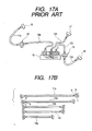
- FIG. 11 One example of methods of thus splicing wires over a plurality of wire harnesses is shown in Fig. 11.
- a wire harness 1 is mounted in an engine room, and a wire harness 2 is mounted on an instrument panel. These wire harnesses 1 and 2 are connected together through a connector 3.
- a circuit group 4 of the wire harness 1 comprises two wires A and one wire B, and in Fig. 11, the two lower wires B and A are spliced to the uppermost wire A.
- the wires A, B and C are used in accordance with equipment specifications. More specifically, the wires A are connected to units provided as standard (that is, in all variations), and wires B and C are connected to units provided in accordance with the variations.
- a circuit group 5 of the wire harness 2 comprises wires A, B and C, and the two lower wires A and C are spliced to the uppermost wire B.
- a sheath is removed from an arbitrary portion of a sheathed wire 6, and a wire 7 is connected to this sheath-removed portion, and these connected portions are spliced together by press-deforming a press-fastening member 8.
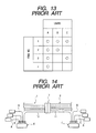
- Fig. 14 the construction of wire harnesses is similar to that shown in Fig. 11, and therefore, only splice portions will be described.
- Fig. 14 two wires A and one wire B are spliced to a circuit group 10 of a wire harness 1 through a joint connector 6, and one wire A, one wire B and one wire B are spliced to a circuit group 11 of a wire harness 2 through another joint connector 7.
- each of the joint connectors 6 and 7 comprises a connector 8, into which crimp-type terminals secured rcspectively to one ends of the wires A to C are inserted, and a bus bar connector 9 containing bus bars 9a.
- the wires 10 and 11, connected through a connector 3, are connected to the joint connectors 6 and 7, respectively, and the wires A to C are spliced over the wire harnesses 1 and 2 through the wires 10 and 11.
- the wires A to C can be spliced over the wire harnesses 1 and 2 in accordance with the selected Item Number. Therefore, it is not necessary to produce four kinds of wire harnesses corresponding respectively to the four Item Nos. 1 to 4, and there are achieved advantages that the cost of production of the wire harnesses is prevented from increasing, and that the production of the wire harnesses can be carried out easily.
- This CAN is capable of effecting a multiplex communication (that is, a serial data communication) at high speed, and therefore, the number of wires can be much reduced, and a compact, lightweight design of a wire harness can be achieved.
- a shielded wire as shown in Fig. 18A, is used as a communication wire (that is, a serial data wire), used in the CAN, in order to eliminate the effects of noises, and such serial data wires are often spliced over wire harnesses.
- reference numerals 11, 12 and 13 denote wire harnesses, and in view of the productivity and the ability of mounting on a vehicle body, these wire harnesses 11, 12 and 13 of suitable lengths are provided in a divided manner, and are mounted respectively at various portions such as an engine room, a dash panel and an instrument panel.
- the wire harnesses 11 to 13 include their respective serial data wires 11a, 12a, 12b, 12c and 13a each including a shielded wire. As shown in Fig. 17B, each of these serial data wires comprises two wires a and b and one drain wire c. This drain wire c forms a metal film, and these wires are collectively covered with a tube:
- one end of the serial data wire 11a is connected to an ECU 16, and the other end of this serial data wire 11a is connected to one end of the serial data wire 12a through a connector 14.
- the other end of this serial data wire 12a is connected to a joint connector 19 containing bus bars.
- serial data wire 12b One end of the serial data wire 12b is connected to an ECU 17, and the other end of this serial data wire 12b is connected to the joint connector 19.
- serial data wire 12c One end of the serial data wire 12c is connected to one end of the serial data wire 13a through a connector 15, and the other end of this serial data wire 12c is connected to the joint connector 19.
- the other end of the serial data wire 13a is connected to an ECU 18.
- serial data wires 12a to 12c are thus spliced to the joint connector, and with this arrangement the serial data wires 11a, 12a to 12c and 13a arc spliced over the wire harnesses 11 to 13 as shown in Fig. 16.
- the associated serial data wires, as well as associated wires for supplying power or merely for transmitting signals, are connected together (in a wire-to-wire manner).
- the serial data wires 11a, 12a to 12c and 13a are different in length.
- the serial data wire 11a is 1000 mm in length
- the serial data wire 12a is 700 mm in length
- the serial data wires 12b and 12c are 500 mm in length
- the serial data wire 13a is 300 mm in length.
- serial data wire examples include a twist pair wire 41, shown in Fig. 18B, and a tubed wire 42 shown in Fig. 18C, and any other suitable form of wire can be used.
- the single serial data wire usually comprises a plurality of wires, and therefore for splicing the serial data wires over the wire harnesses 11 to 13, sheaths are removed from the ends of the serial data wires 11a, 12a, 12c and 13a. Then the terminals are connected to these ends and inserted into the connectors 14 and 15. Therefore, there has been encountered a problem that the time and labor required for the sheath-removing step, the terminal-connecting step and the step of inserting the terminals into the connectors, increase as compared with the case of using simple wires, and the operation for splicing the serial data wires is cumbersome.
- the tube is removed, the sheaths are removed from the ends of the two wires a and b , and the drain wire c in the form of a metal film is separated from the end portions of these wires, and is bundled. Thereafter, the terminals are press-fastened to the wires a and b, respectively.
- the drain wire c a sheath is removed from an arbitrary portion of a wire, to which a terminal is beforehand press-fastened.
- the drain wire c is connected to this sheath-removed portion, and is press-fastened thereto by a press-fastening member.
- terminal-connected portions of shielded wires shown in Fig. 17, are simplified for convenience, but it will be appreciated that the above-mentioned time and labor are required.
- the three wire harnesses 11 to 13 are connected together, and the serial data wires are spliced.
- four or more wire harnesses are connected together, there is required an operation in which sheaths are removed from end portions of serial data wires, and then terminals are connected to these ends. Then they are inserted into connectors. Therefore, in this case, there has been encountered a problem that the operation for splicing the serial data wires is more cumbersome.
- the sheaths are removed from the ends of the serial data wires 11a, 12a, 12c and 13a, and the terminals are secured to these ends, Then these serial data wires are connected in a wire-to-wire manner by the connectors 14 and 15 and are spliced by the joint connector 19 for the wire harness 12.
- these operations are required. Therefore, the degree of freedom of the splicing position of the serial data wires is lowered, and the serial data wires need to be set to different lengths. In addition, the noise-shielding performance is lowered because of the increased amount of removal of the sheaths.
- the two wire harnesses 12a and 12c are connected together, thereby splicing the wires.
- a wire or wires similar in construction to the wires 11a and 13a, are further needed, and the number of the wires further increases, and therefore the production of the wire harnesses has become more cumbersome.
- a joint connector 6 including bus bars 9a (see Fig. 15) having, for example, one input portion and three output portions, there are encountered problems that the joint connector 6 (or 7) has an increased size and that a large space is needed for mounting the large-size joint connector 6 (or 7) on a vehicle body panel.
- the amount of removal of sheaths from the serial data wires can be reduced, thereby enhancing the noise shielding performance.
- the present invention provides a vehicle wiring construction that includes a plurality of sub wire harnesses each having an end connector.
- the sub wire harnesses are configured to be connected to each other when the end connectors are coupled to each other.
- Each sub wire harness has at least one joint wire attached thereto.
- At least one joint connector is provided, and is configured to hold and electrically interconnect the joint wires that are respectively attached to the sub wire harnesses.
- the at least one joint connector is configured to be positioned away from the end connectors so that the joint wires can be connected independently to the at least one joint connector without being connected to the end connectors.
- the at least one joint wire comprises at least one data communication wire.
- the data communication wires are configured to respectively extend between the at least one joint connector and electronic control units to transmit data to a respective one of the electronic control units.
- the electronic control units can be intercommunicated via the at least one joint connector.
- the data communication wire is a serial data communication wire, and is formed from either one of a shielded wire, a twist pair wire or a tubed wire.
- the data communication wires are of substantially the same length. Consequently, electrical characteristics of data communication between the electronic control units can be substantially the same.
- the vehicle wiring construction has a sub-connector for receiving and holding the at least one joint wire attached to the sub wire harness.
- the sub-connectors are configured to be accommodated within the joint connector.
- the at least one joint connector is mounted on an electrical connection box positioned in the proximity of the end connectors.
- the at least one joint connector may be mounted on a bracket of a vehicle body positioned in the proximity of the end connectors, or may be mounted at any suitable location such as the one at one of the sub wire harnesses, preferably in the proximity of the end connectors.
- the at least one joint connector is formed unitarily in one piece with an electrical connection box positioned in the proximity of said end connectors, and forms a joint wiring configuration to electrically interconnect the joint wires and an internal circuit of the electrical connection box.
- the present invention provides a wire harness structure in which a wire harness, including a serial data wire for effecting a serial data communication, is divided, and the divided wire harnesses are connected together through connection means, and a part of the serial data wire are spliced over the plurality of divided wire harnesses without being connected to the connection means.
- a sub-connector to which ends of the part of the serial data wire are connected.
- a joint connector for splicing the serial data wires disposed respectively within the sub-connector.
- the serial data wires, provided on the wire harnesses are connected to the sub-connector, and this sub-connector is connected to the joint connector.
- the serial data wires, provided respectively on the plurality of wire harnesses can be spliced over the wire harnesses.
- the serial data wires For installing the wire harnesses on the vehicle body, the serial data wires, provided respectively on the divided wire harnesses, are connected to the sub-connector, and the sub-connector is connected to the joint connector at the time of installing these wire harnesses on the vehicle body.
- the serial data wires can be easily spliced. Therefore, the serial data wires can be easily connected to the proper portion of the joint connector in a collected manner.
- the serial data wire may be a shielded wire.
- the serial data wire may be a twist pair wire.
- the serial data wire may be a tubed wire.
- any one of the above serial data wires has noise-shielding properties, and therefore the noise-shielding performance can be positively enhanced.
- the serial data wires may be set to generally about the same length.
- serial data wires are spliced at the joint connector while the other ends of these serial data wires are connected respectively to ECUs.
- the serial data wires may be set to generally about the same length.
- the joint connector may be provided in the vicinity of the connection means.
- the joint connector may be provided in the vicinity of the connection means through which the wire harnesses are connected together, and therefore, the connection between the wire harnesses and the splicing of the serial data wires can be effected at one time in a common space on the vehicle body at which only a narrow installation space is available because of the layout of the equipments and the like.
- the joint connector may be mounted on an electrical part fixedly mounted on the vehicle body.
- any electrical part such as an ECU, a junction box, a relay box, a fuse box, a radio, a clock and various meters, can be provided in the vicinity of the connection means, and the joint connector may be mounted on this electrical part.
- the region, at which electric power is supplied to the wire harnesses, and the region, at which the joint connector is fixedly mounted, can be set to the same region. Therefore, the space required for mounting the joint connector can be reduced.
- the joint connector may be mounted on a bracket mounted on the vehicle body.
- the bracket when the bracket may be mounted on an arbitrary portion of the vehicle body, the position of mounting of the connection means is not limited, and the degree of freedom of the mounting position of the connection means can be increased.
- the joint connector may be mounted on an arbitrary one of the wire harnesses disposed in the vicinity of the connection means.
- the joint connector can be fixed without the need for mounting any bracket on the vehicle body.
- the joint connector may contain a branch wiring for splicing a maximum of three serial data wires.
- the joint connector can be formed into a compact, lightweight design, and therefore, the joint connector can be arranged easily by mounting the joint connector directly on the wire harness by a tape or on the nearby electrical part, so that the operations for installing and mounting the wire harnesses, including the serial data wires, can be effected easily.
- the joint connector serving as the splicing portion for the serial data wires, can be arranged freely, and therefore, the installation of the serial data wires can be simplified, thereby enhancing the efficiency of the mounting operation.
- each of the relatively-expensive serial data wires can be connected to the unit in the shortest path, thereby reducing the cost.
- the joint connector may be formed unitarily in one piece or integrally with an electronic unit, and contains a branch wiring for splicing two serial data wires and an internal circuit of the electronic unit.
- the wire harness-connecting operation at the connector portion, the serial data wire-splicing operation, and the operation for connecting the electronic unit to ordinary wires can be effected at one time, and the efficiency of the operation for mounting the structure on the vehicle body can be further enhanced.
- the number of the serial data wires for respectively transferring serial data to the electronic units can be reduced, thereby further reducing the cost.
- the present invention provides a wire harness structure wherein a wire harness, including a plurality of wires, is divided, and the divided wire harnesses are connected together through connection means.
- the structure includes sub-connectors, which are separate from the connection means and to which ends of part of the wires of the divided wire harnesses are connected, and a joint connector, which is provided in the vicinity of the connection means so as to splice the wires disposed within the sub-connectors.
- the part of the wires of the wire harnesses are spliced together by the joint connector over the divided wire harnesses.
- part of the wires of the divided wire harnesses may be connected to the sub-connectors, and these sub-connectors may be connected to the joint connector provided in the vicinity of the connection means.
- part of the wires of the divided wire harnesses can be spliced over the wire harnesses.
- these wire harnesses can be supplied to a manufacturer in such a manner that parts of the wires, provided on the wire harnesses, arc connected to the sub-connectors, and therefore on the part of the manufacturer, the wires can be easily spliced together merely by connecting the sub-connectors to the joint connector. Therefore, the wires can be easily connected to the proper portion of the joint connector in a collected manner.
- the joint connector may be provided in the vicinity of the connection means through which the divided wire harnesses are connected together, and therefore, the connection between the wire harnesses and the splicing of the wires can be effected in a common space on the vehicle body, at which only a narrow installation space is available because of the layout of electrical equipments, an engine and the like.
- the joint connector for splicing purposes can be separate from the connection means. Therefore, the joint connector of high versatility can be formed into a compact and lightweight design, the cost is low, and the installation space for the joint connector can be reduced.
- the joint connector may be mounted on an electrical part fixedly mounted on a vehicle body.
- the joint connector may be mounted on this electrical part.
- the region, at which electric power is supplied to the wire harnesses, and the region, at which the joint connector is fixedly mounted can be set to the same region, and the space required for mounting the joint connector can be reduced.
- the joint connector may be mounted on a bracket fixedly mounted on the vehicle body.
- the position of mounting of the connection means is not limited, and the degree of freedom of the mounting position of the connection means can be increased.
- the joint connector may be mounted on the wire harness disposed in the vicinity of the connection means.
- the joint connector can be fixed without the need for mounting any bracket on the vehicle body.
- Figs. 1A to 9 show the first embodiment of a wire harness structure of the present invention, and the wire harness structure of this embodiment forms a CAN (Control Area Network) for effecting a serial data communication.
- CAN Controller Area Network
- FIGs. 1A to 3 reference numerals 21, 22 and 23 dcnote wire harnesses.
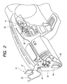
- these wire harnesses 21, 22 and 23 of suitable lengths are provided in a divided manner and are mounted respectively at various portions, such as an engine room 61, a dash panel 62 and an instrument panel 63 (see Fig. 2).
- the wire harness 21 is mounted in the engine room 61
- the wire harness 22 is mounted on the dash panel 62
- the wire harness 23 is mounted on the instrument panel 63.
- Fig. 2 shows a front seat portion of the vehicle body
- reference numeral 64 denotes a grommet.
- Connectors 24 and 25, serving as connection means for effecting a wire-to-wire connection, are mounted respectively on ends of the wire harnesses 21 and 22, and the wire harnesses 21 and 22 are connected together through these connectors 24 and 25.
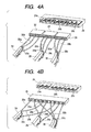
- the wire harness 21 includes a shielded wire 26 serving as a serial data wire, and as shown in Fig. 4A, this shielded wire 26 includes two wires 26a and 26b, and a drain wire 26c forming a metal film. These wires may be covered with a tube.
- a connector 51 may be mounted on one end of this shielded wire 26, and this connector 51 is adapted to be connected to a device, such as an A/T ECU (Automatic Transmission Electronic Control Unit) 27 for controlling an automatic transmission.
- A/T ECU Automatic Transmission Electronic Control Unit
- the other end of the shielded wire 26 is connected to a sub-connector 28, and terminals, connected respectively to the wires 26a to 26c, are adapted to be inserted into this sub-connector 28 as shown in Figs. 4A and 18A.
- the sub-connector 28 is adapted to be connected to a joint connector 29 containing bus bars 29a to 29c serving as branch wiring.
- the wires 26a to 26c are spliced to other two shielded wires by the joint connector 29.
- the wire harness 22 includes at least one shielded wire 30, and as shown in Fig. 4A, this shielded wire 30 includes two wires 30a and 30b, and a drain wire 30c forming a metal film, and these wires 30a, 30b and 30c are covered with a tube.
- a connector 52 is mounted on one end of this shielded wire 30, and this connector 52 is adapted to be connected to a meter ECU 31 for controlling an indication in a meter.
- the other end of the shielded wire 30 is connected to a sub-connector 35, and terminals, connected respectively to the wires 30a to 30c, are adapted to be inserted into this sub-connector 35 as shown in Fig. 4A.
- This sub-connector 35 is adapted to be connected to the joint connector 29, and the wires 30a to 30c are spliced by the joint connector 29.
- the wire harness 23 includes one shielded wire 33 (see Fig. 1), and as shown in Fig. 4, this shielded wire 33 comprises two wires 33a and 33b, and a drain wire 33c forming a metal film, and these wires 33a, 33b and 33c may be covered with a tube.
- a connector 53 is mounted on one end of this shielded wire 33, and this connector 53 is adapted to be connected to, for example, an FI (Fuel Injection) ECU 34 for controlling an engine as shown in Fig. 2.
- FI Fluel Injection
- the other end of the shielded wire 33 is connected to a sub-connector 32, and terminals, connected respectively to the wires 33a to 33c, are adapted to be inserted into this sub-connector 32 as shown in Fig. 4A.
- This sub-connector 32 is adapted to be connected to the joint connector 29, and the wires 33a to 33c are spliced by the joint connector 29.
- Fig. 4B shows a modified form of the invention which differs from the arrangement of Fig. 4A in that only one sub-connector 28 is provided,
- the shielded wires 26, 30 and 33 are spliced by the joint connector 29.
- the shielded wires are used as the serial data wires, and therefore, the three bus bars 29a, 29b and 29c, insulated from one another, are contained in the joint connector 29.
- twist pair wires 41 shown in Fig. 18B
- tubed wires 42 shown in Fig. 18C
- the shielded wires 26, 30 and 33 have generally about the same length (e.g., 1200 mm) as shown in Fig. 3B, and information and control signals are transferred between the ECUs 27, 31 and 34 at high speed.
- the joint connector 29 may be provided in the vicinity of the connectors 24 and 25, and in this embodiment the joint connector 29 may be fixedly secured to a bracket 36 mounted on the vehicle body, as shown in Fig. 5.
- the shielded wires 26, 30 and 33 provided respectively on the separate wire harnesses 21, 22 and 23, may be connected to the sub-connectors 28, 32 and 35, respectively, and these sub-connectors 28, 35 and 32 are connected to the joint connector 29 provided in the vicinity of the connectors 24 and 25.
- the shielded wires 26, 30 and 33 of the wire harnesses 21 to 23 can be spliced over the wire harnesses 21 to 23.
- the shielded wires 26, 30 and 33 For mounting the wire harnesses 21 to 23 on the vehicle body, the shielded wires 26, 30 and 33, provided respectively on the wire harnesses 21 to 23, are connected to the sub-connectors 28, 35 and 32, respectively, and the sub-connectors 28, 32 and 35 are connected to the joint connector 29 at the time of installing these wire harnesses on the vehicle body.
- the shielded wires 26, 30 and 33 can be easily spliced. Therefore, the shielded wires 26, 30 and 33 can be easily connected to the proper portion of the joint connector 29 in a collected manner.
- the joint connector 29 may be provided in the vicinity of the connectors 24 and 25 through which the wire harnesses 21 and 22 are connected together. Therefore, the connection between the wire harnesses 21 and 22 and the splicing of the shielded wires 26, 30 and 33 can be effected at one time in a common space on the vehicle body at which only a narrow installation space may be available because of the layout of the equipments and the like.
- the shielded wires 26, 30 and 33 can be set to generally about the same length. Therefore, when the one end portions of the shielded wires 26, 30 and 33 arc spliced to the joint connector 29 while the other ends of these shielded wires 26, 30 and 33 are connected respectively to the ECUs 27, 31 and 34, the high-speed communication can be effected in such a manner that impedances characteristics relative to the ECUs 27, 31 and 34 may be kept constant through the shielded wires 26, 30 and 33, and therefore, the data communication can be effected in a stable, highly-precise manner.
- the impedance characteristics between the ECUs 27, 31 and 34 can be kept constant since the sum of the lengths of the shielded wires 26 and 30 is equal to the sum of the lengths of the shielded wires 26 and 33. Therefore, the stable high-speed communication can be effected.
- the impedance characteristics, obtained when data is transferred from the shielded wire 26 through the shielded wire 30, are not equal to the impedance characteristics obtained when data is transferred from the shielded wire 26 through the shielded wire 33. Therefore, it is considered that the stable high-speed communication can not be effected.
- the joint connector 29 may be mounted on the bracket 36 as shown in Fig. 5. Therefore, when the bracket 36 is mounted at an arbitrary portion of the vehicle body, the position of mounting of the connectors 24 and 25 is not limited, and the degree of freedom of the mounting position of the connectors 24 and 25 can be increased.
- joint connector 29 is mounted on the bracket 36
- this joint connector 29 may be mounted on, for example, a fuse box 37 fixedly mounted by screws or the like on the vehicle body within the passenger room, the engine room or the like, as shown in Fig. 6.
- the region at which electric power is supplied to the wire harnesses 21 to 23, and the region at which the joint connector 29 may be fixedly mounted can be set to about the same region, and the space required for mounting the joint connector 29 can be reduced.
- the mounting portion for mounting the joint connector 29 may be provided at the fuse box, and the joint connector 29 may be mounted on this fuse box.
- the joint connector 29 may be fixedly mounted through the fuse box.
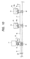
- the part that is mounted on the vehicle body for fixing the joint connector 29 is not limited to the fuse box but can be the control unit (ECU), disposed near to the connectors as shown in Fig. 10, or any other electrical part (e.g., a clock and a radio) mounted on the vehicle.
- the joint connector 29 may be mounted on an arbitrary one (c.g., the wire harness 22) of the wire harnesses, disposed near to the connectors 24 and 25, by a tape 39 or other means. With this arrangement, the joint connector 29 can be fixed without the need for mounting the bracket on the vehicle body.
- the direction of connection of the sub-connectors 28, 32 and 35 to the joint connector 29 may be the same as the direction of the extending of the wire harnesses 21 and 22.
- the direction of connection of the sub-connectors 28, 32 and 35 to the joint connector 29 may be perpendicular to the direction of extending of the wire harnesses 21 and 22.
- the wire harness structure is divided into the three sections, the wire harness structure may be divided into four or more sections.
- shielded wires are used as the serial data wires, twist pair wires 41, shown in Fig. 18B, or tubed wires 42, shown in Fig. 18C, may be used.
- the joint connector 29 may be provided near to an obstacle 56 mounted on the vehicle body 55. With this arrangement, the joint connector 29 can interfere directly with the obstacle 56, and the wire harness 21, 22 or 23 is prevented from interfering with the obstacle 56, and therefore is prevented from being damaged.
- Figs. 9 and 10 show a second embodiment of a wire harness structure of the present invention.
- Fig. 19 shows a structure merely embodying the invention as defined in aspect 1.
- Fig. 19 shows the wire harness structure in which a large-size joint connector 81 is provided in the vicinity of a connector 80, forming a wire-to-wire connection portion for wire harnesses, and the serial data wires 83 to 87, each connected to a corresponding sub-connector 82, are spliced by the joint connector, and may be connected to electronic units 90 to 94 (an FI-ECU and other ECUs).
- the operation for splicing the serial data wires can be reduced so as to enhance the efficiency of the operation.
- the serial data wires, extending from the single large joint connector 81 are connected to the units, respectively. Therefore with respect to the layout, the position of mounting of the joint connector 81 on the vehicle body, as well as a mounting space, must be secured. In addition, the installation or arrangement of the wire harnesses is complicated, and therefore there are still room for improvement of the operation efficiency.
- Fig. 9 instead of the large joint connector 81, there arc used joint connectors 51a to 51c, each containing only a bus bar 70 (serving as branch wiring) required for splicing three serial data wires, and the joint connectors 51a to 51c are located in a distributed manner in the vicinity of the wire harnesses according to the need, and the serial data wires are spliced by these joint connectors.
- a bus bar 70 serving as branch wiring
- Reference numerals 52 to 58 denote the serial data wires which are spliced by the joint connectors 51a to 51c, and are connected to the electronic units 90 to 94 or other joint connectors.
- the joint connectors 51a to 51c can be formed into a compact, lightweight design, and therefore, the joint connectors 51a to 51c can be arranged easily by mounting the joint connectors 51a to 51c directly on the wire harnesses by a tape or on nearby electrical parts, so that the operations for installing and mounting the wire harnesses, including the serial data wires, can be effected easily.
- the joint connectors 51a to 51c serving as the splicing portions for the serial data wires, can be arranged freely, and therefore, the installation of the serial data wires can be simplified, thereby enhancing the efficiency of the mounting operation.
- each of the relatively-expensive serial data wires can be connected to the unit in the shortest path, thereby reducing the cost.
- a fuse box 71 and electronic units 72 and 73 are disposed near to connectors, respectively.
- the fuse box 71 is of such a construction that a joint connector 51a of a compact type as described above can be attached to this fuse box 71.
- Each of the electronic units 71 and 72 includes a joint connector portion 79 containing a bus bar 79a for splicing two serial data wires and a serial data wire trans-receiving portion, contained in the electronic unit, together.
- Reference numerals 74 to 78 denote the serial data wires spliced by the joint connectors 79.
- the wire harness-connecting operation at the connector portions 81 to 83, the serial data wire-splicing operation, and the operation for connecting the electrical part (the fuse box 71 and the electronic units 72 and 73) to ordinary wires can be effected at one time, and the efficiency of the operation for mounting the structure on the vehicle body can be further enhanced.
- the serial data wires for respectively transferring serial data to the electronic units 72 and 73, the electronic units 91, 92 and 93 (shown in Fig. 9) and the wires 53, 55 and 57 (shown in Fig. 9), connected respectively to the joint connectors 51a to 51c can be omitted, and therefore the cost can be further reduced.
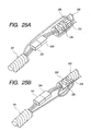
- Figs. 20 to 27 show a third embodiment of a wire harness structure of the present invention.
- reference numerals 221 and 222 denote wire harnesses.
- these wire harnesses 221 and 222 of suitable lengths are provided in a divided manner, and are mounted respectively at various portions, such as an engine room, an instrument panel, door, a seat and the like.
- the wire harness 221 is mounted in the engine room, and the wire harness 222 is mounted on the instrument panel.
- Connectors 223 and 224 serving as connection means, are mounted respectively on ends of the wire harnesses 221 and 222, and the wire harnesses 221 and 222 are connected together through these connectors 224 and 225, thus providing the wire harness structure of the so-called wire-to-wire type.
- Wires 225a, 225b and 225c which are part of wires forming the wire harness 221, are connected to a sub-connector 226. As shown in Fig. 22, crimp-type terminals, secured respectively to the wires 225a to 225c, are inserted into this sub-connector 226, and this sub-connector 226 is connected to a joint connector 228, containing a bus bar 228a, and by doing so, the wires 225a to 225c are spliced together by the joint connector 228.
- Wires 229a, 229b and 229c which are part of wires forming the wire harness 222, are connected to a sub-connector 230, and this sub-connector 230 has the same construction as that shown in Fig. 22. Therefore, the wires 229a to 229c are spliced together by the joint connector 228.
- the wires 225a to 225c and 229a to 229c are spliced together by the joint connector 228.
- wires 225a to 225c (229a to 229c) are shown as being separate from the wire harness 221 (222), the wires 225a to 225c (229a to 229c) are actually fixed by a tape T to the wire harness 221 (222) along an axis of the wire harness 221 (222).
- the joint connector 228 is provided in the vicinity of the connectors 223 and 224.
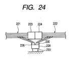
- the joint connector 228 is mounted on, for example, a fuse box 232 fixedly mounted on a vehicle body by screws or the like within the engine room or the passenger room, as shown in Fig. 23.
- the mounting portion for mounting the joint connector 228 is provided at the fuse box, and the joint connector 228 is mounted on this fuse box, and thus the joint connector 228 is fixedly mounted on the vehicle body through the fuse box.
- the part, on which the joint connector 228 is mounted is not limited to the fuse box, but can be an electrical part (e.g. a control unit (ECU), a clock or a radio) disposed near to the connectors 223 and 224.
- the wires 225a to 225c and the wires 229a to 229c, provided on the separate wire harnesses 221 and 222, are connected to the sub-connectors 226 and 230, and these sub-connectors 226 and 230 are connected to the joint connector 228 provided in the vicinity of the connectors 223 and 224.
- part (225a to 225c and 229a to 229c) of the wires of the separate wire harnesses 221 and 222 can be spliced together over the wire harnesses 221 and 222.
- these wire harnesses can be supplied to a manufacturer in such a manner that the wires 225a to 225c and 229a to 229c, provided on the wire harnesses 221 and 222, are connected to the sub-connectors 226 and 230, and therefore on the part of the manufacturer, the wires 225a to 225c and 229a to 229c can be easily spliced together merely by connecting the sub-connectors 226 and 230 to the joint connector 228. Therefore, the wires 225a to 225c and 229a to 229c can be easily connected to the proper portion of the joint connector 228 in a collected manner.
- the joint connector 228 can be separate from the connectors 223 and 224, and therefore, the joint connector 228 can be formed into a compact, lightweight design, and a space required for mounting the joint connector 228 can be reduced.
- the joint connector 228 is provided in the vicinity of the connectors 223 and 224 through which the wire harnesses 221 and 222 are connected together, and therefore, the connection between the wire harnesses 221 and 222 and the splicing of the wires 225a to 225c and 229a to 229c can be effected in a common space on the vehicle body panel at which only a narrow installation space is available because of the layout of the electrical equipments, the engine and so on.
- the joint connector 228 is mounted on the fuse box 232 mounted on the vehicle body panel, and therefore the region at which electric power is supplied to the wire harnesses 221 and 222, and the region at which the joint connector 228 is fixedly mounted, can be set to about the same region, and the space, required for mounting the joint connector 228, can be reduced.
- joint connector 228 is mounted on the fuse box 232, this mounting portion is not limited to the fuse box, and the joint connector 228 may be mounted on a bracket 233 mounted on the vehicle body panel, as shown in Fig. 24.
- the position of mounting of the connectors 223 and 224 is not limited, and the degree of freedom of the mounting position of the connectors 223 and 224 can be increased.
- the joint connector 228 may be mounted on an arbitrary one (for example, the wire harness 222) of the wire harnesses, disposed in the vicinity of the connectors 223 and 224, by a tape 241 or other means. In this case, the joint connector 228 can be fixed without the need for mounting any bracket on the vehicle body panel.
- joint connector 228 can thus be mounted on the arbitrary one of the wire harnesses, disposed near to the connectors 223 and 224, by the tape or other means, since the joint connector 228 can be formed into a compact, lightweight design as described above.
- the joint connector 228 may be provided near to an obstacle 241 mounted on the vehicle body panel 231. With this arrangement, the joint connector 228 can interfere directly with the obstacle 241, and the wire harness 221 or 222 is prevented from interfering with the obstacle 241, and therefore is prevented from being damaged.
- the wire harness structure is divided into the two sections, the wire harness structure may be divided into three or more sections.
- the serial data wires, provided on the plurality of wire harnesses are connected to the sub-connectors, respectively, and these sub-connectors are connected to the joint connector provided in the vicinity of the connection means, and by doing so, the serial data wires, provided on the plurality of wire harnesses, can be spliced over the wire harnesses.
- the conventional operation for connecting the end portions of the serial data wires to the connectors is not necessary, and the efficiency of the operation for splicing the serial data wires can be enhanced.
- the splicing position of the serial data wires is prevented from being limited, and the degree of freedom of the splicing position of the serial data wires can be enhanced.
- the serial data wires are connected to the sub-connectors, respectively, and the sub-connectors are connected to the joint connector at the time of installing these wire harnesses on the vehicle body.
- the serial data wires can be easily spliced. Therefore, the serial data wires can be easily connected to the proper portion of the joint connector in a collected manner.
- Each of the serial data wires includes a shielded wire, a twist pair wire or a tubed wire, and therefore noises can be positively removed.
- the one end portions of the serial data wires may be spliced to the joint connector while the other ends of these serial data wires are connected respectively to the ECUs.
- the serial data wires are set to generally the same length, the impedances characteristics between the ECUs are kept constant through the serial data wires, and by doing so, the stable data communication can be effected.
- the joint connector is provided in the vicinity of the connection means through which the wire harnesses are connected together, and therefore, the connection between the wire harnesses and the splicing of the serial data wires can be effected at one time in a common space on the vehicle body at which only a narrow installation space is available because of the layout of the equipments and the like.
- the joint connector can be mounted on this electrical part.
- the region at which electric power is supplied to the wire harnesses, and the region at which the joint connector is fixedly mounted can be set to the same region, and the space required for mounting the joint connector can be reduced.
- the position of mounting of the connection means is not limited, and the degree of freedom of the mounting position of the connection means can be increased.
- the joint connector When the joint connector is mounted on the arbitrary wire harness disposed near to the connection means, the joint connector can be fixed without the need for mounting any bracket on the vehicle body.
- the joint connector contains the branch wiring for splicing a maximum of three serial data wires, and therefore the joint connector can be formed into a compact, lightweight design.
- the joint connector can be arranged easily by mounting the joint connector directly on the wire harness by a tape or on the nearby electrical part, so that the operations for installing and mounting the wire harnesses, including the serial data wires, can be effected easily.
- the joint connectors serving as the splicing portions for the serial data wires, can be arranged freely, and therefore the installation of the serial data wires can be simplified, thereby enhancing the efficiency of the mounting operation.
- each of the relatively-expensive serial data wires can be connected to the unit in the shortest path, thereby reducing the cost.
- the joint connector may be formed integrally with the electronic unit, and contains the branch wiring for splicing two serial data wires and the internal circuit of the electronic unit, and therefore the wire harness-connecting operation at the connector portion, the serial data wire-splicing operation, and the operation for connecting the electronic unit to ordinary wires can be effected at one time, and the efficiency of the operation for mounting the structure on the vehicle body can be further enhanced.
- the number of the serial data wires for respectively transferring serial data to the electronic units can be reduced, thereby further reducing the cost.
- part of the wires of the divided wire harnesses are connected to the sub-connectors, and these sub-connectors arc connected to the joint connector provided in the vicinity of the connection means.
- these wire harnesses can be supplied to a manufacturer in such a manner that part of the wires, provided on the wire harnesses, are connected to the sub-connectors, and therefore on the part of the manufacturer, the wires can be easily spliced together merely by connecting the sub-connectors to the joint connector. Therefore, the wires can be easily connected to the proper portion of the joint connector in a collected manner,
- the joint connector may be provided in the vicinity of the connection means through which the divided wire harnesses are connected together, and therefore, the connection between the wire harnesses and the splicing of the wires can be effected in a common space on the vehicle body at which only a narrow installation space is available because of the layout of electrical equipments, an engine and the like.
- the joint connector for splicing purposes can be separate from the connection means, and therefore the joint connector of high versatility can be formed into a compact, lightweight design, the cost is low, and the installation space for the joint connector can be reduced.
- any electrical part such as a fuse box
- the joint connector is mounted on this electrical part.
- the position of mounting of the connection means is not limited, and the degree of freedom of the mounting position of the connection means can be increased.
- the joint connector can be fixed without the need for mounting any bracket on the vehicle body
Applications Claiming Priority (4)
| Application Number | Priority Date | Filing Date | Title |
|---|---|---|---|
| JP2000234469A JP3559227B2 (ja) | 2000-08-02 | 2000-08-02 | ワイヤハーネス構造 |
| JP2000234469 | 2000-08-02 | ||
| JP2000240143 | 2000-08-08 | ||
| JP2000240143A JP3617808B2 (ja) | 2000-08-08 | 2000-08-08 | ワイヤハーネス構造 |
Publications (3)
| Publication Number | Publication Date |
|---|---|
| EP1177951A2 true EP1177951A2 (de) | 2002-02-06 |
| EP1177951A3 EP1177951A3 (de) | 2003-10-08 |
| EP1177951B1 EP1177951B1 (de) | 2006-07-26 |
Family
ID=26597231
Family Applications (1)
| Application Number | Title | Priority Date | Filing Date |
|---|---|---|---|
| EP01118531A Expired - Lifetime EP1177951B1 (de) | 2000-08-02 | 2001-08-01 | Kabelbaumstruktur |
Country Status (3)
| Country | Link |
|---|---|
| US (1) | US6503098B2 (de) |
| EP (1) | EP1177951B1 (de) |
| DE (1) | DE60121681T2 (de) |
Cited By (3)
| Publication number | Priority date | Publication date | Assignee | Title |
|---|---|---|---|---|
| EP1335463A2 (de) * | 2002-02-08 | 2003-08-13 | Delphi Technologies, Inc. | Positioniereinrichtung |
| FR2842955A1 (fr) * | 2002-07-29 | 2004-01-30 | Peugeot Citroen Automobiles Sa | Systeme de raccordement d'un capteur de vitesse et d'un temoin d'usure de frein, au reste des circuits d'un vehicule |
| US11225194B2 (en) * | 2019-05-16 | 2022-01-18 | Stoneridge Electronics Ab | Camera mirror system vehicle integration |
Families Citing this family (44)
| Publication number | Priority date | Publication date | Assignee | Title |
|---|---|---|---|---|
| JP2002236725A (ja) * | 2001-02-13 | 2002-08-23 | Hitachi Ltd | 電力需給調整装置および電力需給方法 |
| JP2002368766A (ja) * | 2001-06-05 | 2002-12-20 | Auto Network Gijutsu Kenkyusho:Kk | ワイヤーハーネスシステム |
| US6822459B1 (en) * | 2001-06-15 | 2004-11-23 | Lsi Logic Corporation | Testing implementation for signal characterization |
| DE10219439B4 (de) * | 2002-05-02 | 2005-05-12 | Lisa Dräxlmaier GmbH | Steuerungssystem für Kraftfahrzeuge |
| US20040026998A1 (en) * | 2002-07-24 | 2004-02-12 | Henriott Jay M. | Low voltage electrified furniture unit |
| US7018232B2 (en) * | 2003-08-04 | 2006-03-28 | German Antonio Carmona | Wiring module for automotive vehicle |
| US6881093B2 (en) * | 2003-08-04 | 2005-04-19 | German Antonio Carmona | Wiring module for automotive vehicle |
| JP3984579B2 (ja) * | 2003-09-16 | 2007-10-03 | 株式会社オートネットワーク技術研究所 | インバータ用コネクタ装置 |
| JP4486422B2 (ja) * | 2004-06-25 | 2010-06-23 | 矢崎総業株式会社 | 集中分岐型ネットワークシステム及びジョイントコネクタ |
| US7134908B2 (en) * | 2004-07-23 | 2006-11-14 | Hon Hai Precision Ind. Co., Ltd. | Single-port to multi-port cable assembly |
| US6935902B1 (en) * | 2004-08-05 | 2005-08-30 | Ching Lin Chou | Coupler device for power supply facility |
| US20070026738A1 (en) * | 2005-07-26 | 2007-02-01 | Roger Eichman | Accessory fuse harness |
| US7561445B2 (en) * | 2005-11-10 | 2009-07-14 | Nissan Motor Co., Ltd. | Harness routing structure for vehicle |
| US8068991B2 (en) * | 2005-11-30 | 2011-11-29 | The Invention Science Fund I, Llc | Systems and methods for transmitting pathogen related information and responding |
| US8002179B2 (en) * | 2005-12-20 | 2011-08-23 | Honda Motor Co., Ltd. | Hidden console display |
| US7243987B1 (en) * | 2006-01-31 | 2007-07-17 | Nissan Technical Center North America, Inc. | Apparatus and method for noise reduction in a vehicle |
| GB0608832D0 (en) * | 2006-05-04 | 2006-06-14 | Airbus Uk Ltd | Aircraft wiring installation |
| US7344406B2 (en) * | 2006-05-12 | 2008-03-18 | Astoria Industries Of Iowa | Wiring harness connector for a truck topper |
| US7819219B2 (en) * | 2006-12-31 | 2010-10-26 | Honda Motor Co., Ltd. | Lockable cover for electronic control unit |
| US8653365B1 (en) * | 2009-01-23 | 2014-02-18 | Claude W. Mixon | Overfill warning wiring system for tank trucks |
| US7901215B1 (en) * | 2009-10-20 | 2011-03-08 | GM Global Technology Operations LLC | Electrical harness assemblies |
| US9093188B1 (en) * | 2009-12-14 | 2015-07-28 | i-Lighting, LLC | Wiring harness having interchangeable connectors |
| JP5216095B2 (ja) | 2010-02-17 | 2013-06-19 | 株式会社オートネットワーク技術研究所 | 短絡回路を含むワイヤハーネス及びその製造方法 |
| US9214832B2 (en) * | 2011-06-23 | 2015-12-15 | Siemens Industry, Inc. | Parallel electric service system and method using meter socket and load center combination |
| US10367270B2 (en) | 2015-05-27 | 2019-07-30 | Intelligent Technologies International, Inc. | Vehicle wire harness |
| US9796406B2 (en) * | 2015-07-02 | 2017-10-24 | Kubota Corporation | Electric power steering unit with offset link mechanism |
| JP6374894B2 (ja) | 2016-02-02 | 2018-08-15 | 矢崎総業株式会社 | 車両用回路体 |
| JP6374893B2 (ja) | 2016-02-02 | 2018-08-15 | 矢崎総業株式会社 | 車両用回路体 |
| JP2017136926A (ja) | 2016-02-02 | 2017-08-10 | 矢崎総業株式会社 | 車両用回路体および車両用回路配索システム |
| JP6353858B2 (ja) * | 2016-02-22 | 2018-07-04 | 矢崎総業株式会社 | ワイヤハーネス構造 |
| JP6301382B2 (ja) * | 2016-02-25 | 2018-03-28 | 矢崎総業株式会社 | ワイヤハーネス |
| JP6686833B2 (ja) * | 2016-10-12 | 2020-04-22 | 住友電装株式会社 | 導電路 |
| JP6761398B2 (ja) * | 2017-09-20 | 2020-09-23 | 株式会社オートネットワーク技術研究所 | ワイヤーハーネス及びワイヤーハーネスの接続構造 |
| CN110800070B (zh) | 2017-11-29 | 2021-12-10 | 住友电装株式会社 | 带有托架的导电通路 |
| JP6644824B2 (ja) * | 2018-04-04 | 2020-02-12 | 矢崎総業株式会社 | 分岐回路体及び電線の分岐方法 |
| JP6691164B2 (ja) * | 2018-04-04 | 2020-04-28 | 矢崎総業株式会社 | 分岐回路体及び電線の分岐方法 |
| JP7006556B2 (ja) * | 2018-09-28 | 2022-01-24 | 住友電装株式会社 | 配線部材 |
| JP6902008B2 (ja) * | 2018-10-24 | 2021-07-14 | 矢崎総業株式会社 | シート付ハーネス |
| JP6914905B2 (ja) * | 2018-11-29 | 2021-08-04 | 矢崎総業株式会社 | ボンダーキャップの収容構造、電気接続箱、及びワイヤハーネス |
| DE202019100105U1 (de) * | 2019-01-10 | 2020-04-16 | Innotec Motion GmbH | Sitzmöbelchassis |
| DE202019100110U1 (de) * | 2019-01-10 | 2020-04-16 | Innotec Motion GmbH | Sitzmöbelchassis |
| JP7205243B2 (ja) | 2019-01-16 | 2023-01-17 | 住友電装株式会社 | ブラケット付き導電路 |
| JP7371505B2 (ja) * | 2020-01-20 | 2023-10-31 | 住友電装株式会社 | ワイヤハーネス |
| US20220037060A1 (en) * | 2020-08-03 | 2022-02-03 | iLux electric (Cablage Kumar Inc.) | Molded wiring harness device and method therefor |
Citations (4)
| Publication number | Priority date | Publication date | Assignee | Title |
|---|---|---|---|---|
| EP0334343A2 (de) * | 1988-03-25 | 1989-09-27 | Yazaki Corporation | Kabelbaumkupplungselement an einem Instrumentenbrett |
| FR2687854A1 (fr) * | 1992-02-20 | 1993-08-27 | Texton | Agencement de cablage electrique des dispositifs electriques d'un ensemble tel qu'un vehicule automobile. |
| US5623169A (en) * | 1991-03-28 | 1997-04-22 | Yazaki Corporation | Electrical wiring harness structure for vehicle |
| US5668415A (en) * | 1994-07-18 | 1997-09-16 | Kansei Corporation | Arrangement of harnesses in a vehicle |
Family Cites Families (9)
| Publication number | Priority date | Publication date | Assignee | Title |
|---|---|---|---|---|
| US4195894A (en) * | 1977-05-04 | 1980-04-01 | Amerace Corporation | Electrical connector and electrical connection system employing the same |
| GB2109644B (en) * | 1978-09-29 | 1983-10-12 | Yazaki Corp | Wiring head for use in the manufacture of a wire harness |
| JPS58111281A (ja) * | 1981-12-25 | 1983-07-02 | 本田技研工業株式会社 | カプラ−接続装置 |
| US4941845A (en) * | 1989-06-07 | 1990-07-17 | Traveling Software, Inc. | Data transfer cable |
| US4971576A (en) * | 1989-11-03 | 1990-11-20 | The Budd Company | Modular power cord system |
| US5234360A (en) * | 1992-06-25 | 1993-08-10 | Robert V. Smith | Multiple outlet extension cord |
| US5501605A (en) * | 1993-06-07 | 1996-03-26 | Yazaki Corporation | Wiring harness assembly for vehicles |
| JP3237412B2 (ja) * | 1994-08-31 | 2001-12-10 | 住友電装株式会社 | ワイヤハーネスおよび該ワイヤハーネスの製造方法 |
| US6291770B1 (en) * | 1999-05-14 | 2001-09-18 | Leoni Wiring Systems, Inc. | Wiring system and method therefor |
-
2001
- 2001-08-01 EP EP01118531A patent/EP1177951B1/de not_active Expired - Lifetime
- 2001-08-01 DE DE60121681T patent/DE60121681T2/de not_active Expired - Fee Related
- 2001-08-02 US US09/919,962 patent/US6503098B2/en not_active Expired - Fee Related
Patent Citations (4)
| Publication number | Priority date | Publication date | Assignee | Title |
|---|---|---|---|---|
| EP0334343A2 (de) * | 1988-03-25 | 1989-09-27 | Yazaki Corporation | Kabelbaumkupplungselement an einem Instrumentenbrett |
| US5623169A (en) * | 1991-03-28 | 1997-04-22 | Yazaki Corporation | Electrical wiring harness structure for vehicle |
| FR2687854A1 (fr) * | 1992-02-20 | 1993-08-27 | Texton | Agencement de cablage electrique des dispositifs electriques d'un ensemble tel qu'un vehicule automobile. |
| US5668415A (en) * | 1994-07-18 | 1997-09-16 | Kansei Corporation | Arrangement of harnesses in a vehicle |
Cited By (5)
| Publication number | Priority date | Publication date | Assignee | Title |
|---|---|---|---|---|
| EP1335463A2 (de) * | 2002-02-08 | 2003-08-13 | Delphi Technologies, Inc. | Positioniereinrichtung |
| EP1335463A3 (de) * | 2002-02-08 | 2004-08-25 | Delphi Technologies, Inc. | Positioniereinrichtung |
| FR2842955A1 (fr) * | 2002-07-29 | 2004-01-30 | Peugeot Citroen Automobiles Sa | Systeme de raccordement d'un capteur de vitesse et d'un temoin d'usure de frein, au reste des circuits d'un vehicule |
| EP1387447A1 (de) * | 2002-07-29 | 2004-02-04 | Peugeot Citroen Automobiles SA | System zum Verbinden eines Geschwindigkeitssensors und eines Verschleisssensors für Bremse an den Rest von Schaltungen eines Fahrzeugs |
| US11225194B2 (en) * | 2019-05-16 | 2022-01-18 | Stoneridge Electronics Ab | Camera mirror system vehicle integration |
Also Published As
| Publication number | Publication date |
|---|---|
| EP1177951A3 (de) | 2003-10-08 |
| DE60121681T2 (de) | 2007-08-02 |
| EP1177951B1 (de) | 2006-07-26 |
| US20020019165A1 (en) | 2002-02-14 |
| DE60121681D1 (de) | 2006-09-07 |
| US6503098B2 (en) | 2003-01-07 |
Similar Documents
| Publication | Publication Date | Title |
|---|---|---|
| EP1177951B1 (de) | Kabelbaumstruktur | |
| JP7123551B2 (ja) | 車両用の回路体 | |
| JP3617808B2 (ja) | ワイヤハーネス構造 | |
| CN107539241B (zh) | 线束 | |
| CN110970762B (zh) | 线束 | |
| HU206657B (en) | Electrical cabling system for motor vehicles | |
| US6822168B2 (en) | Cable harness arrangement | |
| CN110962768B (zh) | 线束 | |
| JPH1140281A (ja) | ジョイントコネクタの固定構造 | |
| JP7168533B2 (ja) | ワイヤハーネス | |
| JP2560161Y2 (ja) | 電気コネクタ | |
| JP2647641B2 (ja) | 自動車のワイヤーハーネス装置 | |
| JP7081944B2 (ja) | 車両用の回路体 | |
| GB2269708A (en) | Method of producing wiring harnesses | |
| JP3184435B2 (ja) | 自動車用ワイヤハーネス | |
| JP3559227B2 (ja) | ワイヤハーネス構造 | |
| JP2929917B2 (ja) | ワイヤハーネスの防水構造 | |
| JP3545510B2 (ja) | 自動車用ワイヤハーネス | |
| KR19990019649U (ko) | 자동차 와이어 하니스 | |
| JP2002200946A (ja) | ワイヤハーネス組付け車両部品モジュール | |
| JPS62116334A (ja) | 車輌用ワイヤハ−ネス装置 | |
| US20240116467A1 (en) | Electrical connection box | |
| JP3312537B2 (ja) | 自動車用分岐接続装置 | |
| JPH04274942A (ja) | 車両用電気配索構造 | |
| JP2000092649A (ja) | プロテクタ |
Legal Events
| Date | Code | Title | Description |
|---|---|---|---|
| PUAI | Public reference made under article 153(3) epc to a published international application that has entered the european phase |
Free format text: ORIGINAL CODE: 0009012 |
|
| AK | Designated contracting states |
Kind code of ref document: A2 Designated state(s): AT BE CH CY DE DK ES FI FR GB GR IE IT LI LU MC NL PT SE TR |
|
| AX | Request for extension of the european patent |
Free format text: AL;LT;LV;MK;RO;SI |
|
| RIN1 | Information on inventor provided before grant (corrected) |
Inventor name: SOSHINO, TORU Inventor name: AOKI, HITOSHI |
|
| PUAL | Search report despatched |
Free format text: ORIGINAL CODE: 0009013 |
|
| AK | Designated contracting states |
Kind code of ref document: A3 Designated state(s): AT BE CH CY DE DK ES FI FR GB GR IE IT LI LU MC NL PT SE TR |
|
| AX | Request for extension of the european patent |
Extension state: AL LT LV MK RO SI |
|
| 17P | Request for examination filed |
Effective date: 20040128 |
|
| AKX | Designation fees paid |
Designated state(s): DE FR GB |
|
| 17Q | First examination report despatched |
Effective date: 20041012 |
|
| GRAP | Despatch of communication of intention to grant a patent |
Free format text: ORIGINAL CODE: EPIDOSNIGR1 |
|
| GRAS | Grant fee paid |
Free format text: ORIGINAL CODE: EPIDOSNIGR3 |
|
| GRAA | (expected) grant |
Free format text: ORIGINAL CODE: 0009210 |
|
| RIN1 | Information on inventor provided before grant (corrected) |
Inventor name: AOKI, HITOSHI Inventor name: SOSHINO, TORU |
|
| AK | Designated contracting states |
Kind code of ref document: B1 Designated state(s): DE FR GB |
|
| REG | Reference to a national code |
Ref country code: GB Ref legal event code: FG4D |
|
| RIN1 | Information on inventor provided before grant (corrected) |
Inventor name: SOSHINO, TORU Inventor name: AOKI, HITOSHI |
|
| PGFP | Annual fee paid to national office [announced via postgrant information from national office to epo] |
Ref country code: GB Payment date: 20060802 Year of fee payment: 6 |
|
| REF | Corresponds to: |
Ref document number: 60121681 Country of ref document: DE Date of ref document: 20060907 Kind code of ref document: P |
|
| ET | Fr: translation filed | ||
| PLBE | No opposition filed within time limit |
Free format text: ORIGINAL CODE: 0009261 |
|
| STAA | Information on the status of an ep patent application or granted ep patent |
Free format text: STATUS: NO OPPOSITION FILED WITHIN TIME LIMIT |
|
| 26N | No opposition filed |
Effective date: 20070427 |
|
| PGFP | Annual fee paid to national office [announced via postgrant information from national office to epo] |
Ref country code: DE Payment date: 20070726 Year of fee payment: 7 |
|
| GBPC | Gb: european patent ceased through non-payment of renewal fee |
Effective date: 20070801 |
|
| REG | Reference to a national code |
Ref country code: FR Ref legal event code: ST Effective date: 20080430 |
|
| PG25 | Lapsed in a contracting state [announced via postgrant information from national office to epo] |
Ref country code: FR Free format text: LAPSE BECAUSE OF NON-PAYMENT OF DUE FEES Effective date: 20070831 |
|
| PG25 | Lapsed in a contracting state [announced via postgrant information from national office to epo] |
Ref country code: GB Free format text: LAPSE BECAUSE OF NON-PAYMENT OF DUE FEES Effective date: 20070801 |
|
| PG25 | Lapsed in a contracting state [announced via postgrant information from national office to epo] |
Ref country code: FR Free format text: LAPSE BECAUSE OF NON-PAYMENT OF DUE FEES Effective date: 20060831 |
|
| PG25 | Lapsed in a contracting state [announced via postgrant information from national office to epo] |
Ref country code: DE Free format text: LAPSE BECAUSE OF NON-PAYMENT OF DUE FEES Effective date: 20090303 |