BACKGROUND OF THE INVENTION
1. Field of Invention
This invention relates to a wire harness structure for connecting
separate (divided) wire harnesses together, and more particularly to a wire harness
structure capable of efficiently splicing (joining) wires of the wire harnesses together.
2. Description of Related Art
Electrical equipment mounted on an automobile obtain electric power
and a lot of information fed from switch sensors and the like, through wires, and
therefore wire harnesses, having a large amount of wires concealed from the view, are
installed in the vehicle. Here, the term "wire harness" means a bundle of wires of
various kinds joined together by a corrugated tube, a tape or the like.
In view of the productivity and the ability of mounting on a vehicle
body, the wire harnesses of suitable lengths are provided in a divided manner, and are
mounted respectively at various portions, such as an engine room, an instrument panel
a door and a seat, and the wire harnesses are connected together through suitable
connection means such as a connector. This is usually referred to as "wire-to-wire
connection".
The wire harnesses connecting the electrical equipments are arranged
in complicated paths, and therefore, parts of wires forming the wire harnesses need to
be spliced, and particularly at the wire-to-wire portion, the wires often need to be
spliced over the wire harnesses This has been the cause of an increased number of the
wires.
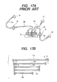
One example of methods of thus splicing wires over a plurality of
wire harnesses is shown in Fig. 11.
In Fig. 11, a wire harness 1 is mounted in an engine room, and a wire
harness 2 is mounted on an instrument panel. These wire harnesses 1 and 2 are
connected together through a connector 3.
A circuit group 4 of the wire harness 1 comprises two wires A and
one wire B, and in Fig. 11, the two lower wires B and A are spliced to the uppermost
wire A.
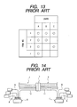
As shown in Fig. 13 described in detail later, the wires A, B and C are
used in accordance with equipment specifications. More specifically, the wires A are
connected to units provided as standard (that is, in all variations), and wires B and C
are connected to units provided in accordance with the variations.
As shown in Fig. 11, a circuit group 5 of the wire harness 2 comprises
wires A, B and C, and the two lower wires A and C are spliced to the uppermost wire
B.
Therefore, these wires A to C are spliced over the wire harnesses 1
and 2 through the connector 3.
As shown in Figs. 12A and 12B, with respect to the splicing of the
wires A to C of the circuit groups 4 and 5, a sheath is removed from an arbitrary
portion of a sheathed wire 6, and a wire 7 is connected to this sheath-removed portion,
and these connected portions are spliced together by press-deforming a press-fastening
member 8.
Assuming that with respect to wire harnesses of this kind, there are
four Item Nos. 1 to 4 of splice specifications as shown in Fig. 13, it is necessary to
splice the circuit groups 4 and 5 of the wire harnesses 1 and 2 in accordance with the
splice specifications (including four Item Nos. 1 to 4) after removing the sheaths from
the wires A to C. Therefore, it has been necessary to produce four kinds of circuit
groups corresponding respectively to the four Item Nos. 1 to 4, and therefore the
production cost of the wire harnesses has increased, and the production has been very
cumbersome.
In order to overcome such a disadvantage, methods of splicing wires
by the use of a joint connector have been extensively used. One example of such
splicing methods is shown in Fig. 14. In Fig. 14, the construction of wire harnesses is
similar to that shown in Fig. 11, and therefore, only splice portions will be described.
In Fig. 14, two wires A and one wire B are spliced to a circuit group
10 of a wire harness 1 through a joint connector 6, and one wire A, one wire B and
one wire B are spliced to a circuit group 11 of a wire harness 2 through another joint
connector 7.
As shown in Fig. 15, each of the joint connectors 6 and 7 comprises a
connector 8, into which crimp-type terminals secured rcspectively to one ends of the
wires A to C are inserted, and a bus bar connector 9 containing bus bars 9a.
As shown in Fig. 14, the wires 10 and 11, connected through a
connector 3, are connected to the joint connectors 6 and 7, respectively, and the wires
A to C are spliced over the wire harnesses 1 and 2 through the wires 10 and 11.
In the splicing method using these joint connectors 6 and 7, merely by
connecting the wires A to C to the joint connectors 6 and 7 in accordance with a
selected one of the Item Nos. 1 to 4 (as shown in Fig. 13), the wires A to C can be
spliced over the wire harnesses 1 and 2 in accordance with the selected Item Number.
Therefore, it is not necessary to produce four kinds of wire harnesses corresponding
respectively to the four Item Nos. 1 to 4, and there are achieved advantages that the
cost of production of the wire harnesses is prevented from increasing, and that the
production of the wire harnesses can be carried out easily.
In recent years, the control of automobiles has become more and
more advanced, and many ECUs (Electronic Control Units) have been mounted on the
automobile, and the high-speed transfer of information between the ECUs for an
engine, an ABS (Antilock Brake System), a transmission and the like has become
indispensable. The transfer of signals between the engine, the ABS, the transmission
and the like is enabled by a CAN (Control Area Network) forming a high-speed
communication network in the automobile,
This CAN is capable of effecting a multiplex communication (that is,
a serial data communication) at high speed, and therefore, the number of wires can be
much reduced, and a compact, lightweight design of a wire harness can be achieved.
However, generally, a shielded wire, as shown in Fig. 18A, is used as
a communication wire (that is, a serial data wire), used in the CAN, in order to
eliminate the effects of noises, and such serial data wires are often spliced over wire
harnesses.
One conventional method of splicing serial data wires of this type is
shown in Figs. 16 and 17. Basically, this method also uses joint connectors as in Fig.
4.
In Figs. 16 and 17, reference numerals 11, 12 and 13 denote wire
harnesses, and in view of the productivity and the ability of mounting on a vehicle
body, these wire harnesses 11, 12 and 13 of suitable lengths are provided in a divided
manner, and are mounted respectively at various portions such as an engine room, a
dash panel and an instrument panel.
The wire harnesses 11 to 13 include their respective serial data wires
11a, 12a, 12b, 12c and 13a each including a shielded wire. As shown in Fig. 17B, each
of these serial data wires comprises two wires a and b and one drain wire c. This drain
wire c forms a metal film, and these wires are collectively covered with a tube:
As shown in Fig. 17A, one end of the serial data wire 11a is
connected to an ECU 16, and the other end of this serial data wire 11a is connected to
one end of the serial data wire 12a through a connector 14. The other end of this
serial data wire 12a is connected to a joint connector 19 containing bus bars.
One end of the serial data wire 12b is connected to an ECU 17, and
the other end of this serial data wire 12b is connected to the joint connector 19.
One end of the serial data wire 12c is connected to one end of the
serial data wire 13a through a connector 15, and the other end of this serial data wire
12c is connected to the joint connector 19. The other end of the serial data wire 13a is
connected to an ECU 18.
The serial data wires 12a to 12c are thus spliced to the joint
connector, and with this arrangement the serial data wires 11a, 12a to 12c and 13a arc
spliced over the wire harnesses 11 to 13 as shown in Fig. 16.
In the connectors 14 and 15, the associated serial data wires, as well
as associated wires for supplying power or merely for transmitting signals, are
connected together (in a wire-to-wire manner).
The serial data wires 11a, 12a to 12c and 13a are different in length.
For example, the serial data wire 11a is 1000 mm in length, and the serial data wire 12a
is 700 mm in length. The serial data wires 12b and 12c are 500 mm in length, and the
serial data wire 13a is 300 mm in length.
Other forms of serial data wire include a twist pair wire 41, shown in
Fig. 18B, and a tubed wire 42 shown in Fig. 18C, and any other suitable form of wire
can be used.
In this method of splicing the serial data wires, however, the single
serial data wire usually comprises a plurality of wires, and therefore for splicing the
serial data wires over the wire harnesses 11 to 13, sheaths are removed from the ends
of the serial data wires 11a, 12a, 12c and 13a. Then the terminals are connected to
these ends and inserted into the connectors 14 and 15. Therefore, there has been
encountered a problem that the time and labor required for the sheath-removing step,
the terminal-connecting step and the step of inserting the terminals into the connectors,
increase as compared with the case of using simple wires, and the operation for
splicing the serial data wires is cumbersome.
More specifically, as shown in an enlarged portion A of Fig. 18A, for
connecting the terminals to the shielded wire, the tube is removed, the sheaths are
removed from the ends of the two wires a and b, and the drain wire c in the form of a
metal film is separated from the end portions of these wires, and is bundled.
Thereafter, the terminals are press-fastened to the wires a and b, respectively. With
respect to the drain wire c, a sheath is removed from an arbitrary portion of a wire, to
which a terminal is beforehand press-fastened. The drain wire c is connected to this
sheath-removed portion, and is press-fastened thereto by a press-fastening member.
Thus, these operations are required. Incidentally, although terminal-connected
portions of shielded wires, shown in Fig. 17, are simplified for convenience, but it will
be appreciated that the above-mentioned time and labor are required.
In the illustrated conventional construction, the three wire harnesses
11 to 13 are connected together, and the serial data wires are spliced. In the case
where four or more wire harnesses are connected together, there is required an
operation in which sheaths are removed from end portions of serial data wires, and
then terminals are connected to these ends. Then they are inserted into connectors.
Therefore, in this case, there has been encountered a problem that the operation for
splicing the serial data wires is more cumbersome.
In addition, the sheaths are removed from the ends of the serial data
wires 11a, 12a, 12c and 13a, and the terminals are secured to these ends, Then these
serial data wires are connected in a wire-to-wire manner by the connectors 14 and 15
and are spliced by the joint connector 19 for the wire harness 12. Thus, these
operations are required. Therefore, the degree of freedom of the splicing position of
the serial data wires is lowered, and the serial data wires need to be set to different
lengths. In addition, the noise-shielding performance is lowered because of the
increased amount of removal of the sheaths.
Further, in such a conventional splicing method, however, it is
necessary to provide the wires 11a and 13a for connecting the wire harnesses 12a and
12c together, and to splice the wires A to C by connecting these wires 11a and 13a
respectively to the joint connectors 14 and 15. Thus, there are required the two wires
11a and 13a provided over the wire harnesses 12a and 12c, and the number of the
wires increases, and therefore, the production of the wire harnesses has become
cumbersome.
In the conventional construction, the two wire harnesses 12a and 12c
are connected together, thereby splicing the wires. In the case where three or more
wire harnesses are connected together, a wire or wires, similar in construction to the
wires 11a and 13a, are further needed, and the number of the wires further increases,
and therefore the production of the wire harnesses has become more cumbersome.
As shown in Fig. 13, in the case where splicing wires A, B and C of
two wire harnesses (e.g., 12a and 12c in Fig. 17A) are connected together by a joint
connector 6 (or 7), including bus bars 9a (see Fig. 15) having, for example, one input
portion and three output portions, there are encountered problems that the joint
connector 6 (or 7) has an increased size and that a large space is needed for mounting
the large-size joint connector 6 (or 7) on a vehicle body panel.
SUMMARY OF THE INVENTION
It is therefore an object of this invention to provide a vehicle wiring
construction or a wire harness structure in which the efficiency of an operation for
splicing data communication wires, preferably in the form of serial data wires, can be
enhanced, and the degree of freedom of the splicing position of the serial data wires
can be enhanced, thereby enhancing the degree of freedom of setting of wire lengths.
In addition, the amount of removal of sheaths from the serial data wires can be
reduced, thereby enhancing the noise shielding performance.
To solve the above problems, the present invention provides a vehicle
wiring construction that includes a plurality of sub wire harnesses each having an end
connector. The sub wire harnesses are configured to be connected to each other when
the end connectors are coupled to each other. Each sub wire harness has at least one
joint wire attached thereto. At least one joint connector is provided, and is configured
to hold and electrically interconnect the joint wires that are respectively attached to the
sub wire harnesses. The at least one joint connector is configured to be positioned
away from the end connectors so that the joint wires can be connected independently
to the at least one joint connector without being connected to the end connectors.
In another aspect of the present invention, the at least one joint wire
comprises at least one data communication wire. The data communication wires are
configured to respectively extend between the at least one joint connector and
electronic control units to transmit data to a respective one of the electronic control
units. Accordingly, the electronic control units can be intercommunicated via the at
least one joint connector. Preferably, the data communication wire is a serial data
communication wire, and is formed from either one of a shielded wire, a twist pair wire
or a tubed wire.
In a further aspect of the present invention, the data communication
wires are of substantially the same length. Consequently, electrical characteristics of
data communication between the electronic control units can be substantially the same.
In a further aspect of the present invention, the vehicle wiring
construction has a sub-connector for receiving and holding the at least one joint wire
attached to the sub wire harness. The sub-connectors are configured to be
accommodated within the joint connector.
In a further aspect of the present invention, the at least one joint
connector is mounted on an electrical connection box positioned in the proximity of
the end connectors. Alternatively, the at least one joint connector may be mounted on
a bracket of a vehicle body positioned in the proximity of the end connectors, or may
be mounted at any suitable location such as the one at one of the sub wire harnesses,
preferably in the proximity of the end connectors.
In another aspect of the present invention, the at least one joint
connector is formed unitarily in one piece with an electrical connection box positioned
in the proximity of said end connectors, and forms a joint wiring configuration to
electrically interconnect the joint wires and an internal circuit of the electrical
connection box.
Further, the present invention provides a wire harness structure in
which a wire harness, including a serial data wire for effecting a serial data
communication, is divided, and the divided wire harnesses are connected together
through connection means, and a part of the serial data wire are spliced over the
plurality of divided wire harnesses without being connected to the connection means.
There is provided a sub-connector to which ends of the part of the serial data wire are
connected. There is provided a joint connector for splicing the serial data wires
disposed respectively within the sub-connector.
In this case, the serial data wires, provided on the wire harnesses, are
connected to the sub-connector, and this sub-connector is connected to the joint
connector. By doing so, the serial data wires, provided respectively on the plurality of
wire harnesses, can be spliced over the wire harnesses.
As a result, a conventional operation, in which sheaths are removed
from the end portions of the serial data wires, and then these end portions are
connected to a connector, can be minimized. Therefore, the efficiency of the operation
for splicing the serial data wires can be enhanced. Moreover, the end portions of the
serial data wires do not need to be connected to the wire-to-wire connector which
connects the wire harnesses together. Therefore, the splicing position of the serial
data wires is prevented from being limited, and the degree of freedom of the splicing
position of the serial data wires can be enhanced.
For installing the wire harnesses on the vehicle body, the serial data
wires, provided respectively on the divided wire harnesses, are connected to the sub-connector,
and the sub-connector is connected to the joint connector at the time of
installing these wire harnesses on the vehicle body. By doing so, the serial data wires
can be easily spliced. Therefore, the serial data wires can be easily connected to the
proper portion of the joint connector in a collected manner.
In the invention, in order to solve the above problems, the serial data
wire may be a shielded wire.
In the invention, in order to solve the above problems, the serial data
wire may be a twist pair wire.
In the invention, in order to solve the above problems, the serial data
wire may be a tubed wire.
Any one of the above serial data wires has noise-shielding properties,
and therefore the noise-shielding performance can be positively enhanced.
In the invention, in order to solve the above problems, the serial data
wires may be set to generally about the same length.
In this case, one end portions of the serial data wires are spliced at the
joint connector while the other ends of these serial data wires are connected
respectively to ECUs. The serial data wires may be set to generally about the same
length. By doing so, high-speed communications can be effected in such a manner that
impedance characteristics between the ECUs are kept constant through the serial data
wires, and stable data communications can be effected in a stable, highly-precise
manner.
In the invention, in order to solve the above problems, the joint
connector may be provided in the vicinity of the connection means.
In this case, the joint connector may be provided in the vicinity of the
connection means through which the wire harnesses are connected together, and
therefore, the connection between the wire harnesses and the splicing of the serial data
wires can be effected at one time in a common space on the vehicle body at which only
a narrow installation space is available because of the layout of the equipments and the
like.
In the invention, in order to solve the above problems, the joint
connector may be mounted on an electrical part fixedly mounted on the vehicle body.
In this case, if any electrical part, such as an ECU, a junction box, a
relay box, a fuse box, a radio, a clock and various meters, can be provided in the
vicinity of the connection means, and the joint connector may be mounted on this
electrical part. By doing so, the region, at which electric power is supplied to the wire
harnesses, and the region, at which the joint connector is fixedly mounted, can be set
to the same region. Therefore, the space required for mounting the joint connector can
be reduced.
In the invention, in order to solve the above problems, the joint
connector may be mounted on a bracket mounted on the vehicle body.
In this case, when the bracket may be mounted on an arbitrary portion
of the vehicle body, the position of mounting of the connection means is not limited,
and the degree of freedom of the mounting position of the connection means can be
increased.
In the invention, in order to solve the above problems, the joint
connector may be mounted on an arbitrary one of the wire harnesses disposed in the
vicinity of the connection means.
In this case, the joint connector can be fixed without the need for
mounting any bracket on the vehicle body.
In the invention, in order to solve the above problems, the joint
connector may contain a branch wiring for splicing a maximum of three serial data
wires.
In this case, the joint connector can be formed into a compact,
lightweight design, and therefore, the joint connector can be arranged easily by
mounting the joint connector directly on the wire harness by a tape or on the nearby
electrical part, so that the operations for installing and mounting the wire harnesses,
including the serial data wires, can be effected easily.
The joint connector, serving as the splicing portion for the serial data
wires, can be arranged freely, and therefore, the installation of the serial data wires can
be simplified, thereby enhancing the efficiency of the mounting operation. In addition,
each of the relatively-expensive serial data wires can be connected to the unit in the
shortest path, thereby reducing the cost.
In the invention, in order to solve the above problems, the joint
connector may be formed unitarily in one piece or integrally with an electronic unit,
and contains a branch wiring for splicing two serial data wires and an internal circuit of
the electronic unit.
In this case, the wire harness-connecting operation at the connector
portion, the serial data wire-splicing operation, and the operation for connecting the
electronic unit to ordinary wires can be effected at one time, and the efficiency of the
operation for mounting the structure on the vehicle body can be further enhanced. In
addition, the number of the serial data wires for respectively transferring serial data to
the electronic units can be reduced, thereby further reducing the cost.
It is therefore an object of this invention to provide a wire harness
structure in which the number of splicing wires may be prevented from increasing,
thereby enabling the easy production of a wire harness, and besides the efficiency of an
operation, in which the wire harness is mounted on a vehicle body, with the splicing
wires easily collected, can be enhanced, and the cost of the wire harness structure is
reduced.
Further more, the present invention provides a wire harness structure
wherein a wire harness, including a plurality of wires, is divided, and the divided wire
harnesses are connected together through connection means. The structure includes
sub-connectors, which are separate from the connection means and to which ends of
part of the wires of the divided wire harnesses are connected, and a joint connector,
which is provided in the vicinity of the connection means so as to splice the wires
disposed within the sub-connectors. The part of the wires of the wire harnesses are
spliced together by the joint connector over the divided wire harnesses.
In this case, part of the wires of the divided wire harnesses may be
connected to the sub-connectors, and these sub-connectors may be connected to the
joint connector provided in the vicinity of the connection means. By doing so, part of
the wires of the divided wire harnesses can be spliced over the wire harnesses.
As a result, splicing wires for connecting the wire harnesses together
as in the conventional construction are not necessary, and the number of the wires is
reduced. Thus, the production of the wire harness can be carried out easily.
For mounting the wire harnesses on a vehicle body, these wire
harnesses can be supplied to a manufacturer in such a manner that parts of the wires,
provided on the wire harnesses, arc connected to the sub-connectors, and therefore on
the part of the manufacturer, the wires can be easily spliced together merely by
connecting the sub-connectors to the joint connector. Therefore, the wires can be
easily connected to the proper portion of the joint connector in a collected manner.
The joint connector may be provided in the vicinity of the connection
means through which the divided wire harnesses are connected together, and therefore,
the connection between the wire harnesses and the splicing of the wires can be effected
in a common space on the vehicle body, at which only a narrow installation space is
available because of the layout of electrical equipments, an engine and the like.
The joint connector for splicing purposes can be separate from the
connection means. Therefore, the joint connector of high versatility can be formed
into a compact and lightweight design, the cost is low, and the installation space for
the joint connector can be reduced.
In the invention, in order to solve the above problems, the joint
connector may be mounted on an electrical part fixedly mounted on a vehicle body.
In this case, if any electrical part, such as a fuse box, is provided in
the vicinity of the connection means, the joint connector may be mounted on this
electrical part. By doing so, the region, at which electric power is supplied to the wire
harnesses, and the region, at which the joint connector is fixedly mounted, can be set
to the same region, and the space required for mounting the joint connector can be
reduced.
In the invention, in order to solve the above problems, the joint
connector may be mounted on a bracket fixedly mounted on the vehicle body.
In this case, when the bracket is mounted on an arbitrary portion of
the vehicle body, the position of mounting of the connection means is not limited, and
the degree of freedom of the mounting position of the connection means can be
increased.
In the invention, in order to solve the above problems, the joint
connector may be mounted on the wire harness disposed in the vicinity of the
connection means.
In this case, the joint connector can be fixed without the need for
mounting any bracket on the vehicle body.
BRIEF DESCRIPTION OF THE DRAWINGS
The invention is described in detail with regard to the following
figures, wherein:
DETAILED DESCRIPTION OF PREFERRED EMBODIMENTS
A preferred embodiment of the present invention will now be
described with reference to the drawings.
Figs. 1A to 9 show the first embodiment of a wire harness structure
of the present invention, and the wire harness structure of this embodiment forms a
CAN (Control Area Network) for effecting a serial data communication.
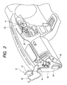
First, the construction will be described. In Figs. 1A to 3, reference
numerals 21, 22 and 23 dcnote wire harnesses. In view of the productivity and the
ability of mounting on a vehicle body, these wire harnesses 21, 22 and 23 of suitable
lengths are provided in a divided manner and are mounted respectively at various
portions, such as an engine room 61, a dash panel 62 and an instrument panel 63 (see
Fig. 2). In this embodiment, the wire harness 21 is mounted in the engine room 61,
and the wire harness 22 is mounted on the dash panel 62, and the wire harness 23 is
mounted on the instrument panel 63. Fig. 2 shows a front seat portion of the vehicle
body, and in Figs. 1A, 1B and 2, reference numeral 64 denotes a grommet.
Connectors 24 and 25, serving as connection means for effecting a
wire-to-wire connection, are mounted respectively on ends of the wire harnesses 21
and 22, and the wire harnesses 21 and 22 are connected together through these
connectors 24 and 25.
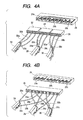
The wire harness 21 includes a shielded wire 26 serving as a serial
data wire, and as shown in Fig. 4A, this shielded wire 26 includes two wires 26a and
26b, and a drain wire 26c forming a metal film. These wires may be covered with a
tube.
As shown in Fig. 1A, a connector 51 may be mounted on one end of
this shielded wire 26, and this connector 51 is adapted to be connected to a device,
such as an A/T ECU (Automatic Transmission Electronic Control Unit) 27 for
controlling an automatic transmission.
The other end of the shielded wire 26 is connected to a sub-connector
28, and terminals, connected respectively to the wires 26a to 26c, are adapted to be
inserted into this sub-connector 28 as shown in Figs. 4A and 18A. The sub-connector
28 is adapted to be connected to a joint connector 29 containing bus bars 29a to 29c
serving as branch wiring. The wires 26a to 26c are spliced to other two shielded wires
by the joint connector 29.
The wire harness 22 includes at least one shielded wire 30, and as
shown in Fig. 4A, this shielded wire 30 includes two wires 30a and 30b, and a drain
wire 30c forming a metal film, and these wires 30a, 30b and 30c are covered with a
tube.
A connector 52 is mounted on one end of this shielded wire 30, and
this connector 52 is adapted to be connected to a meter ECU 31 for controlling an
indication in a meter.
The other end of the shielded wire 30 is connected to a sub-connector
35, and terminals, connected respectively to the wires 30a to 30c, are adapted to be
inserted into this sub-connector 35 as shown in Fig. 4A. This sub-connector 35 is
adapted to be connected to the joint connector 29, and the wires 30a to 30c are spliced
by the joint connector 29.
The wire harness 23 includes one shielded wire 33 (see Fig. 1), and as
shown in Fig. 4, this shielded wire 33 comprises two wires 33a and 33b, and a drain
wire 33c forming a metal film, and these wires 33a, 33b and 33c may be covered with a
tube.
A connector 53 is mounted on one end of this shielded wire 33, and
this connector 53 is adapted to be connected to, for example, an FI (Fuel Injection)
ECU 34 for controlling an engine as shown in Fig. 2.
The other end of the shielded wire 33 is connected to a sub-connector
32, and terminals, connected respectively to the wires 33a to 33c, are adapted to be
inserted into this sub-connector 32 as shown in Fig. 4A. This sub-connector 32 is
adapted to be connected to the joint connector 29, and the wires 33a to 33c are spliced
by the joint connector 29.
Fig. 4B shows a modified form of the invention which differs from the
arrangement of Fig. 4A in that only one sub-connector 28 is provided,
As a result, the shielded wires 26, 30 and 33 are spliced by the joint
connector 29.
In Figs. 4A and 4B, the shielded wires are used as the serial data
wires, and therefore, the three bus bars 29a, 29b and 29c, insulated from one another,
are contained in the joint connector 29. However, in the case where twist pair wires
41 (shown in Fig. 18B) or tubed wires 42 (shown in Fig. 18C) are used as the serial
data wires, it will readily be appreciated that two bus bars are contained in the joint
connector.
In this embodiment, the shielded wires 26, 30 and 33 have generally
about the same length (e.g., 1200 mm) as shown in Fig. 3B, and information and
control signals are transferred between the ECUs 27, 31 and 34 at high speed.
The joint connector 29 may be provided in the vicinity of the
connectors 24 and 25, and in this embodiment the joint connector 29 may be fixedly
secured to a bracket 36 mounted on the vehicle body, as shown in Fig. 5.
In this embodiment, the shielded wires 26, 30 and 33, provided
respectively on the separate wire harnesses 21, 22 and 23, may be connected to the
sub-connectors 28, 32 and 35, respectively, and these sub-connectors 28, 35 and 32
are connected to the joint connector 29 provided in the vicinity of the connectors 24
and 25. By doing so, the shielded wires 26, 30 and 33 of the wire harnesses 21 to 23
can be spliced over the wire harnesses 21 to 23.
Therefore, it is not necessary to effect a conventional operation in
which the sheaths are removed from the end portions of the shielded wires, and then
these end portions are connected to the wire-to-wire connectors. Therefore, the
efficiency of the operation for splicing the shielded wires 26, 30 and 33 can be
enhanced. In addition, since the end portions of the shielded wires 26, 30 and 33 do
not need to be connected to the wire-to- wire connectors 24 and 25, the splicing
position of the shielded wires 26, 30 and 33 is prevented from being limited, and the
degree of freedom of the splicing position of the shielded wires 26, 30 and 33 can be
enhanced.
For mounting the wire harnesses 21 to 23 on the vehicle body, the
shielded wires 26, 30 and 33, provided respectively on the wire harnesses 21 to 23, are
connected to the sub-connectors 28, 35 and 32, respectively, and the sub-connectors
28, 32 and 35 are connected to the joint connector 29 at the time of installing these
wire harnesses on the vehicle body. By doing so, the shielded wires 26, 30 and 33 can
be easily spliced. Therefore, the shielded wires 26, 30 and 33 can be easily connected
to the proper portion of the joint connector 29 in a collected manner.
The joint connector 29 may be provided in the vicinity of the
connectors 24 and 25 through which the wire harnesses 21 and 22 are connected
together. Therefore, the connection between the wire harnesses 21 and 22 and the
splicing of the shielded wires 26, 30 and 33 can be effected at one time in a common
space on the vehicle body at which only a narrow installation space may be available
because of the layout of the equipments and the like.
Since the degree of freedom of the splicing position of the shielded
wires 26, 30 and 33 can be enhanced, the shielded wires 26, 30 and 33 can be set to
generally about the same length. Therefore, when the one end portions of the shielded
wires 26, 30 and 33 arc spliced to the joint connector 29 while the other ends of these
shielded wires 26, 30 and 33 are connected respectively to the ECUs 27, 31 and 34,
the high-speed communication can be effected in such a manner that impedances
characteristics relative to the ECUs 27, 31 and 34 may be kept constant through the
shielded wires 26, 30 and 33, and therefore, the data communication can be effected in
a stable, highly-precise manner.
More specifically, when data is transferred from the shielded wire 26
through the shielded wire 30 and when data is transferred from the shielded wire 26
through the shielded wire 33, the impedance characteristics between the ECUs 27, 31
and 34 can be kept constant since the sum of the lengths of the shielded wires 26 and
30 is equal to the sum of the lengths of the shielded wires 26 and 33. Therefore, the
stable high-speed communication can be effected.
If the sum of the lengths of the shielded wires 26 and 30 is different
from the sum of the lengths of the shielded wires 26 and 33, the impedance
characteristics, obtained when data is transferred from the shielded wire 26 through the
shielded wire 30, are not equal to the impedance characteristics obtained when data is
transferred from the shielded wire 26 through the shielded wire 33. Therefore, it is
considered that the stable high-speed communication can not be effected.
In this embodiment, the joint connector 29 may be mounted on the
bracket 36 as shown in Fig. 5. Therefore, when the bracket 36 is mounted at an
arbitrary portion of the vehicle body, the position of mounting of the connectors 24
and 25 is not limited, and the degree of freedom of the mounting position of the
connectors 24 and 25 can be increased.
In this embodiment, although the joint connector 29 is mounted on
the bracket 36, this joint connector 29 may be mounted on, for example, a fuse box 37
fixedly mounted by screws or the like on the vehicle body within the passenger room,
the engine room or the like, as shown in Fig. 6.
With this arrangement, the region at which electric power is supplied
to the wire harnesses 21 to 23, and the region at which the joint connector 29 may be
fixedly mounted, can be set to about the same region, and the space required for
mounting the joint connector 29 can be reduced.
In this embodiment, the mounting portion for mounting the joint
connector 29 may be provided at the fuse box, and the joint connector 29 may be
mounted on this fuse box. Thus, the joint connector 29 may be fixedly mounted
through the fuse box. However, as will be surmised from Figs. 6A-6C, the part that is
mounted on the vehicle body for fixing the joint connector 29 is not limited to the fuse
box but can be the control unit (ECU), disposed near to the connectors as shown in
Fig. 10, or any other electrical part (e.g., a clock and a radio) mounted on the vehicle.
As shown in Figs. 7A and 7B, the joint connector 29 may be mounted
on an arbitrary one (c.g., the wire harness 22) of the wire harnesses, disposed near to
the connectors 24 and 25, by a tape 39 or other means. With this arrangement, the
joint connector 29 can be fixed without the need for mounting the bracket on the
vehicle body. In the arrangement shown in Fig. 7A, the direction of connection of the
sub-connectors 28, 32 and 35 to the joint connector 29 may be the same as the
direction of the extending of the wire harnesses 21 and 22. In the arrangement shown
in Fig. 7B, the direction of connection of the sub-connectors 28, 32 and 35 to the joint
connector 29 may be perpendicular to the direction of extending of the wire harnesses
21 and 22.
In this embodiment, although the wire harness structure is divided
into the three sections, the wire harness structure may be divided into four or more
sections.
In this embodiment, although the shielded wires are used as the serial
data wires, twist pair wires 41, shown in Fig. 18B, or tubed wires 42, shown in Fig.
18C, may be used.
As shown in Fig. 8, the joint connector 29 may be provided near to an
obstacle 56 mounted on the vehicle body 55. With this arrangement, the joint
connector 29 can interfere directly with the obstacle 56, and the wire harness 21, 22 or
23 is prevented from interfering with the obstacle 56, and therefore is prevented from
being damaged.
Figs. 9 and 10 show a second embodiment of a wire harness structure
of the present invention. For comparison purposes, Fig. 19 shows a structure merely
embodying the invention as defined in aspect 1.
In Figs. 9 and 10, solid lines denote serial data wires, each including a
shielded wire, a twist pair wire (both of which are shown in Fig. 18) and/or others, and
broken lines denote power wires and/or ordinary signal wires. "[ ]" denotes ends of a
corrugated tube or tapes bundling the wires.
Fig. 19 shows the wire harness structure in which a large-size joint
connector 81 is provided in the vicinity of a connector 80, forming a wire-to-wire
connection portion for wire harnesses, and the serial data wires 83 to 87, each
connected to a corresponding sub-connector 82, are spliced by the joint connector, and
may be connected to electronic units 90 to 94 (an FI-ECU and other ECUs).
In this wiring structure, the operation for splicing the serial data wires
can be reduced so as to enhance the efficiency of the operation. However, the serial
data wires, extending from the single large joint connector 81, are connected to the
units, respectively. Therefore with respect to the layout, the position of mounting of
the joint connector 81 on the vehicle body, as well as a mounting space, must be
secured. In addition, the installation or arrangement of the wire harnesses is
complicated, and therefore there are still room for improvement of the operation
efficiency.
In order to overcome these disadvantages, in Fig. 9, instead of the
large joint connector 81, there arc used joint connectors 51a to 51c, each containing
only a bus bar 70 (serving as branch wiring) required for splicing three serial data
wires, and the joint connectors 51a to 51c are located in a distributed manner in the
vicinity of the wire harnesses according to the need, and the serial data wires are
spliced by these joint connectors.
Reference numerals 52 to 58 denote the serial data wires which are
spliced by the joint connectors 51a to 51c, and are connected to the electronic units 90
to 94 or other joint connectors.
With this construction, the joint connectors 51a to 51c can be formed
into a compact, lightweight design, and therefore, the joint connectors 51a to 51c can
be arranged easily by mounting the joint connectors 51a to 51c directly on the wire
harnesses by a tape or on nearby electrical parts, so that the operations for installing
and mounting the wire harnesses, including the serial data wires, can be effected easily.
The joint connectors 51a to 51c, serving as the splicing portions for
the serial data wires, can be arranged freely, and therefore, the installation of the serial
data wires can be simplified, thereby enhancing the efficiency of the mounting
operation. In addition, each of the relatively-expensive serial data wires can be
connected to the unit in the shortest path, thereby reducing the cost.
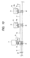
On the other hand, in Fig. 10, a fuse box 71 and electronic units 72
and 73 are disposed near to connectors, respectively. The fuse box 71 is of such a
construction that a joint connector 51a of a compact type as described above can be
attached to this fuse box 71. Each of the electronic units 71 and 72 includes a joint
connector portion 79 containing a bus bar 79a for splicing two serial data wires and a
serial data wire trans-receiving portion, contained in the electronic unit, together.
Reference numerals 74 to 78 denote the serial data wires spliced by
the joint connectors 79.
With this construction, the wire harness-connecting operation at the
connector portions 81 to 83, the serial data wire-splicing operation, and the operation
for connecting the electrical part (the fuse box 71 and the electronic units 72 and 73)
to ordinary wires can be effected at one time, and the efficiency of the operation for
mounting the structure on the vehicle body can be further enhanced. In addition, the
serial data wires for respectively transferring serial data to the electronic units 72 and
73, the electronic units 91, 92 and 93 (shown in Fig. 9) and the wires 53, 55 and 57
(shown in Fig. 9), connected respectively to the joint connectors 51a to 51c, can be
omitted, and therefore the cost can be further reduced.
Figs. 20 to 27 show a third embodiment of a wire harness structure of
the present invention.
First, the construction will be described. In Figs. 20 and 21, reference
numerals 221 and 222 denote wire harnesses. In view of the operation efficiency and
the productivity, these wire harnesses 221 and 222 of suitable lengths are provided in a
divided manner, and are mounted respectively at various portions, such as an engine
room, an instrument panel, door, a seat and the like. In this embodiment, the wire
harness 221 is mounted in the engine room, and the wire harness 222 is mounted on
the instrument panel.
Connectors 223 and 224, serving as connection means, are mounted
respectively on ends of the wire harnesses 221 and 222, and the wire harnesses 221
and 222 are connected together through these connectors 224 and 225, thus providing
the wire harness structure of the so-called wire-to-wire type.
Wires 225a, 225b and 225c, which are part of wires forming the wire
harness 221, are connected to a sub-connector 226. As shown in Fig. 22, crimp-type
terminals, secured respectively to the wires 225a to 225c, are inserted into this sub-connector
226, and this sub-connector 226 is connected to a joint connector 228,
containing a bus bar 228a, and by doing so, the wires 225a to 225c are spliced together
by the joint connector 228.
Wires 229a, 229b and 229c, which are part of wires forming the wire
harness 222, are connected to a sub-connector 230, and this sub-connector 230 has the
same construction as that shown in Fig. 22. Therefore, the wires 229a to 229c are
spliced together by the joint connector 228.
As a result, the wires 225a to 225c and 229a to 229c are spliced
together by the joint connector 228.
In Fig. 20, although the wires 225a to 225c (229a to 229c) are shown
as being separate from the wire harness 221 (222), the wires 225a to 225c (229a to
229c) are actually fixed by a tape T to the wire harness 221 (222) along an axis of the
wire harness 221 (222).
The joint connector 228 is provided in the vicinity of the connectors
223 and 224. In this embodiment, since the wire harnesses 221 and 222 are installed
over the engine room and the instrument panel, the joint connector 228 is mounted on,
for example, a fuse box 232 fixedly mounted on a vehicle body by screws or the like
within the engine room or the passenger room, as shown in Fig. 23.
In this embodiment, the mounting portion for mounting the joint
connector 228 is provided at the fuse box, and the joint connector 228 is mounted on
this fuse box, and thus the joint connector 228 is fixedly mounted on the vehicle body
through the fuse box. However, as will be surmised from Fig. 23, the part, on which
the joint connector 228 is mounted, is not limited to the fuse box, but can be an
electrical part (e.g. a control unit (ECU), a clock or a radio) disposed near to the
connectors 223 and 224.
In this embodiment, the wires 225a to 225c and the wires 229a to
229c, provided on the separate wire harnesses 221 and 222, are connected to the sub-connectors
226 and 230, and these sub-connectors 226 and 230 are connected to the
joint connector 228 provided in the vicinity of the connectors 223 and 224. By doing
so, part (225a to 225c and 229a to 229c) of the wires of the separate wire harnesses
221 and 222 can be spliced together over the wire harnesses 221 and 222.
As a result, splicing wires for connecting the wire harnesses 221 and
222 together as in the conventional construction are not necessary, and the number of
the wires is reduced, and the production of the wire harness can be carried out easily.
For mounting the wire harnesses 221 and 222 on a vehicle body
panel, these wire harnesses can be supplied to a manufacturer in such a manner that the
wires 225a to 225c and 229a to 229c, provided on the wire harnesses 221 and 222, are
connected to the sub-connectors 226 and 230, and therefore on the part of the
manufacturer, the wires 225a to 225c and 229a to 229c can be easily spliced together
merely by connecting the sub-connectors 226 and 230 to the joint connector 228.
Therefore, the wires 225a to 225c and 229a to 229c can be easily connected to the
proper portion of the joint connector 228 in a collected manner.
The joint connector 228 can be separate from the connectors 223 and
224, and therefore, the joint connector 228 can be formed into a compact, lightweight
design, and a space required for mounting the joint connector 228 can be reduced.
The joint connector 228 is provided in the vicinity of the connectors
223 and 224 through which the wire harnesses 221 and 222 are connected together,
and therefore, the connection between the wire harnesses 221 and 222 and the splicing
of the wires 225a to 225c and 229a to 229c can be effected in a common space on the
vehicle body panel at which only a narrow installation space is available because of the
layout of the electrical equipments, the engine and so on.
The joint connector 228 is mounted on the fuse box 232 mounted on
the vehicle body panel, and therefore the region at which electric power is supplied to
the wire harnesses 221 and 222, and the region at which the joint connector 228 is
fixedly mounted, can be set to about the same region, and the space, required for
mounting the joint connector 228, can be reduced.
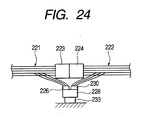
In this embodiment, although the joint connector 228 is mounted on
the fuse box 232, this mounting portion is not limited to the fuse box, and the joint
connector 228 may be mounted on a bracket 233 mounted on the vehicle body panel,
as shown in Fig. 24.
In this case, when the bracket is mounted on an arbitrary portion of
the vehicle body panel, the position of mounting of the connectors 223 and 224 is not
limited, and the degree of freedom of the mounting position of the connectors 223 and
224 can be increased.
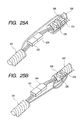
As shown in Figs. 25A and 25B, the joint connector 228 may be
mounted on an arbitrary one (for example, the wire harness 222) of the wire harnesses,
disposed in the vicinity of the connectors 223 and 224, by a tape 241 or other means.
In this case, the joint connector 228 can be fixed without the need for mounting any
bracket on the vehicle body panel.
It will be appreciated that the joint connector 228 can thus be
mounted on the arbitrary one of the wire harnesses, disposed near to the connectors
223 and 224, by the tape or other means, since the joint connector 228 can be formed
into a compact, lightweight design as described above.
As shown in Fig. 26, the joint connector 228 may be provided near to
an obstacle 241 mounted on the vehicle body panel 231. With this arrangement, the
joint connector 228 can interfere directly with the obstacle 241, and the wire harness
221 or 222 is prevented from interfering with the obstacle 241, and therefore is
prevented from being damaged.
In this embodiment, the although the wire harness structure is divided
into the two sections, the wire harness structure may be divided into three or more
sections.
In the present invention, the serial data wires, provided on the
plurality of wire harnesses, are connected to the sub-connectors, respectively, and
these sub-connectors are connected to the joint connector provided in the vicinity of
the connection means, and by doing so, the serial data wires, provided on the plurality
of wire harnesses, can be spliced over the wire harnesses.
As a result, the conventional operation for connecting the end
portions of the serial data wires to the connectors is not necessary, and the efficiency
of the operation for splicing the serial data wires can be enhanced. In addition, since it
is not necessary to connect the end portions of the serial data wires to the connectors
connecting the wire harnesses together, the splicing position of the serial data wires is
prevented from being limited, and the degree of freedom of the splicing position of the
serial data wires can be enhanced.
For installing the wire harnesses on the vehicle body, the serial data
wires, provided respectively on the separate wire harnesses, are connected to the sub-connectors,
respectively, and the sub-connectors are connected to the joint connector
at the time of installing these wire harnesses on the vehicle body. Merely by doing so,
the serial data wires can be easily spliced. Therefore, the serial data wires can be easily
connected to the proper portion of the joint connector in a collected manner.
Each of the serial data wires includes a shielded wire, a twist pair wire
or a tubed wire, and therefore noises can be positively removed.
The one end portions of the serial data wires may be spliced to the
joint connector while the other ends of these serial data wires are connected
respectively to the ECUs. In this case, when the serial data wires are set to generally
the same length, the impedances characteristics between the ECUs are kept constant
through the serial data wires, and by doing so, the stable data communication can be
effected.
The joint connector is provided in the vicinity of the connection
means through which the wire harnesses are connected together, and therefore, the
connection between the wire harnesses and the splicing of the serial data wires can be
effected at one time in a common space on the vehicle body at which only a narrow
installation space is available because of the layout of the equipments and the like.
In the case where the electrical part is provided in the vicinity of the
connection means, the joint connector can be mounted on this electrical part. By doing
so, the region at which electric power is supplied to the wire harnesses, and the region
at which the joint connector is fixedly mounted, can be set to the same region, and the
space required for mounting the joint connector can be reduced.
When the bracket is mounted on an arbitrary portion of the vehicle
body, the position of mounting of the connection means is not limited, and the degree
of freedom of the mounting position of the connection means can be increased.
When the joint connector is mounted on the arbitrary wire harness
disposed near to the connection means, the joint connector can be fixed without the
need for mounting any bracket on the vehicle body.
The joint connector contains the branch wiring for splicing a
maximum of three serial data wires, and therefore the joint connector can be formed
into a compact, lightweight design. Thus, the joint connector can be arranged easily by
mounting the joint connector directly on the wire harness by a tape or on the nearby
electrical part, so that the operations for installing and mounting the wire harnesses,
including the serial data wires, can be effected easily.
The joint connectors, serving as the splicing portions for the serial
data wires, can be arranged freely, and therefore the installation of the serial data wires
can be simplified, thereby enhancing the efficiency of the mounting operation. In
addition, each of the relatively-expensive serial data wires can be connected to the unit
in the shortest path, thereby reducing the cost.
The joint connector may be formed integrally with the electronic unit,
and contains the branch wiring for splicing two serial data wires and the internal circuit
of the electronic unit, and therefore the wire harness-connecting operation at the
connector portion, the serial data wire-splicing operation, and the operation for
connecting the electronic unit to ordinary wires can be effected at one time, and the
efficiency of the operation for mounting the structure on the vehicle body can be
further enhanced. In addition, the number of the serial data wires for respectively
transferring serial data to the electronic units can be reduced, thereby further reducing
the cost.
Further, according to this invention, part of the wires of the divided
wire harnesses are connected to the sub-connectors, and these sub-connectors arc
connected to the joint connector provided in the vicinity of the connection means. By
doing so, part of the wires of the divided wire harnesses can be spliced over the wire
harnesses.
As a result, splicing wires for connecting the wire harnesses together
as in the conventional construction are not necessary, the number of the wires is
reduced, and the production of the wire harness can be carried out easily.
For mounting the wire harnesses on a vehicle body, these wire
harnesses can be supplied to a manufacturer in such a manner that part of the wires,
provided on the wire harnesses, are connected to the sub-connectors, and therefore on
the part of the manufacturer, the wires can be easily spliced together merely by
connecting the sub-connectors to the joint connector. Therefore, the wires can be
easily connected to the proper portion of the joint connector in a collected manner,
The joint connector may be provided in the vicinity of the connection
means through which the divided wire harnesses are connected together, and therefore,
the connection between the wire harnesses and the splicing of the wires can be effected
in a common space on the vehicle body at which only a narrow installation space is
available because of the layout of electrical equipments, an engine and the like.
The joint connector for splicing purposes can be separate from the
connection means, and therefore the joint connector of high versatility can be formed
into a compact, lightweight design, the cost is low, and the installation space for the
joint connector can be reduced.
According to this invention, if any electrical part, such as a fuse box,
may be provided in the vicinity of the connection means, the joint connector is
mounted on this electrical part. By doing so, the region at which electric power is
supplied to the wire harnesses, and the region at which the joint connector is fixedly
mounted, can be set to about the same region, and the space required for mounting the
joint connector can be reduced.
According to this invention, when the bracket is mounted on an
arbitrary portion of the vehicle body, the position of mounting of the connection means
is not limited, and the degree of freedom of the mounting position of the connection
means can be increased.
According to the invention, the joint connector can be fixed without
the need for mounting any bracket on the vehicle body