EP1335463A2 - Positionning device - Google Patents
Positionning device Download PDFInfo
- Publication number
- EP1335463A2 EP1335463A2 EP03002470A EP03002470A EP1335463A2 EP 1335463 A2 EP1335463 A2 EP 1335463A2 EP 03002470 A EP03002470 A EP 03002470A EP 03002470 A EP03002470 A EP 03002470A EP 1335463 A2 EP1335463 A2 EP 1335463A2
- Authority
- EP
- European Patent Office
- Prior art keywords
- positioning device
- cable set
- carrier
- holding
- seal
- Prior art date
- Legal status (The legal status is an assumption and is not a legal conclusion. Google has not performed a legal analysis and makes no representation as to the accuracy of the status listed.)
- Withdrawn
Links
Images

Classifications
-
- H—ELECTRICITY
- H02—GENERATION; CONVERSION OR DISTRIBUTION OF ELECTRIC POWER
- H02G—INSTALLATION OF ELECTRIC CABLES OR LINES, OR OF COMBINED OPTICAL AND ELECTRIC CABLES OR LINES
- H02G3/00—Installations of electric cables or lines or protective tubing therefor in or on buildings, equivalent structures or vehicles
- H02G3/30—Installations of cables or lines on walls, floors or ceilings
Definitions
- the invention relates to a positioning device for lines in cable sets.
- the invention further relates to a method for sealing Connection points, each between several lines of a cable set getting produced.
- electrical Cables used to power components and for signal transmission serve as cable sets or wiring harnesses in which one Large number of electrical cables combined into a bundle are.
- it is necessary that several lines of the cable set are connected to each other and lines at specific positions along the harness led away from the cable set or included in the cable set.
- one that represents the vehicle speed Signal that is generated at one location in the vehicle spatially at several separate locations in the vehicle.
- the Speed signal leading line on the one hand in the vehicle cable set integrated and the other with one or more lines connected, each at a remote position from the cable set branch to feed the signal to the respective component.
- a liaison office on which two or more lines are connected are also referred to as "splice".
- connection points between the lines of particular importance.
- Known solutions that special sealing tubes, heat shrink tubing or Simply commercially available adhesive tapes for sealing the connection points use are time-consuming and costly because, on the one hand are associated with high material consumption and secondly each individual connection point separate from the other connection points must be sealed.
- the known solutions disadvantageous that the relative positions of the individual connection points are undefined and the mutual isolation of the connection points what can not be ensured with sufficient reliability overall, low process reliability as well as that due to the difficult handling of the known solutions at Assembly of cable sets requires a lot of effort.
- the object of the invention is to provide a way to manufacture of cable sets and in particular the sealing of connection points to simplify between several lines of the cable set, wherein In particular, the highest possible level of process security is guaranteed should be and the manufacturing and assembly costs are minimized should.
- the positioning device at least one fixable on a cable set Carrier comprises, which has at least one holding device with which at least one made between several lines of the cable set Connection point can be fixed in a predetermined position on the carrier is.
- the invention provides a positioning device with which the individual Connection points each in a predetermined position relative to Cable set can be fixed by the support of the positioning device attached to the cable set and the connection point to be positioned is fixed to the holding device of the carrier.
- the carrier preferably has a plurality of holding devices, which act against one another are isolated and in particular spatially separated. In this way, several connection points can be made with just one device in defined relative positions to each other on the cable set be positioned, with mutual isolation of the Connection points through the design of the positioning device is guaranteed.
- a particularly simple handling is achieved if according to one particularly preferred embodiment of the invention of the carrier on Cable set can be clamped.
- the carrier can be plugged onto the cable set Be trained riders.
- the carrier is annular.
- the carrier can be as open and in particular slotted ring can be provided. This allows the positioning device pushed in a very simple way over the cable set or be plugged onto the cable set.
- the diameter of the ring-shaped carrier is preferably such that Dimensions of the respective cable set adapted that a safe, clamping position of the positioning device secured against axial relative movements on the cable set is guaranteed.
- the holding device - at on Cable set fixed carrier - on a radially facing away from the cable set Outside of the carrier is arranged.
- the carrier has several holding devices, it is preferred provided that the holding devices in the circumferential direction of the carrier are distributed. In this way, a particularly advantageous Star or wheel-shaped configuration of the positioning device realized in which the holding devices on the outside of the carrier are arranged and - with the bracket fixed to the cable set - from the cable set extend away or point away from the cable set. This will help minimal space requirement for the positioning device according to the invention safe and reliable positioning and mutual isolation of the individual connection points achieved.
- Holding device formed such that the connection point on the Holding device can be clamped. On additional fasteners for fixing the connection points to the positioning device and thus on the cable set can thus be dispensed with in an advantageous manner become.
- the holding device as in Axial direction at least one side open holding chamber for receiving the connection point is formed.
- the holding chamber can be used as a clamping chamber be formed in which the respective connection point is clamped can be.
- the holding chamber can be at least one elastically deflectable Have retaining tab, which by inserting the connection point in the Holding chamber is pushed inwards and the one in the holding chamber positioned connection point is clamped.
- the Connection point thus only needs to be pressed into the holding chamber to be, at least in principle both before and after the Attachment of the carrier to the cable set can be done.
- the positioning device in the Area of the holding device a radial thickness of less than 10 mm, preferably less than 5 mm and particularly preferably about 3 up to 4 mm.
- the radial wall thickness of the carrier is preferably about 1 mm.
- the holding device preferably has a radial height of approximately 2 to 4 mm and preferably from about 3 mm.
- the positioning device is formed in one piece.
- the holding device on the one hand and the carrier on the other hand as separate and interconnectable components can be provided, the
- the type of coupling is basically arbitrary and e.g. as rest, Plug or clip connection can be designed.
- the preferred material for the positioning device is plastic.
- the object underlying the invention is, on the other hand, by a Process with the features of independent process claim 23 and in particular solved in that at least one between several Lines of the cable set formed connection point on the cable set is fixed, and that the cable set in the area of the connection point is provided with a seal so that it is fixed to the cable set Connection point completely surrounded by the seal and in particular is embedded in the seal.
- connection point optimal against external influences such as moisture to protect.
- the cable set only needs to be designed in such a way that the junction is placed at a location along the harness where the seal is needed. In addition to that anyway necessary provision of the seal needs according to the invention only the connection point to be fixed on the cable set.
- connection point is fixed to the cable set, for example simply with a conventional adhesive tape.
- This variant is special advantageous in cases where in a certain position or in a certain area along the cable set only a single connection point is available because then on the relative positions of several There is no need to pay attention to the connection points.
- the method provides that at least one carrier is fixed to the cable set is that the one made before or after fixing the bracket to the harness Connection point by means of a holding device of the carrier in a predetermined position on the carrier is fixed, and that the cable set is provided with the seal in the area of the holding device, that at least the connection point fixed to the carrier is completely from surround the seal and in particular embedded in the seal is.
- connection points first by means of a bracket that can be fixed to the cable set and a holding device of the carrier in a predetermined position be fixed relative to the cable set and then the arrangement from cable set, bracket, holding device and connection point with the Sealing is provided.
- the seal is molded onto the cable set by foaming the connection point, which is fixed in particular by means of a holding device of a carrier fixed to the cable set.
- the seal is preferably designed as a spout, bushing, plug, tube or sleeve. Such a seal is also called "grommet".
- the invention advantageously makes the circumstance to use that in particular in the field of vehicle construction increasingly foamed seals with cable sets or cable harnesses especially in the form of grommets, bushings, plugs, tubes or sleeves are used to make through holes in components of the vehicle through which the cable set or wiring harness passes against the passage of moisture and others to seal external influences. Transitions between wet areas and Dry areas of a vehicle are, for example, in the vehicle front wall trained the vehicle interior from the engine compartment separates.
- the joints to be sealed have been at the Transitions between wet and dry areas distant positions on the cable set, so that it seals especially in wet areas located, special, complex measures had to be hit.
- additional measures can be taken be dispensed with if according to a particularly preferred one Embodiment the seal is also the component with the cable set through a passage opening that e.g. in a vehicle front wall is trained, is passed. This takes place Sealing of the connection points to a certain extent automatically a seal that is required anyway to seal the passage opening.
- the invention also relates to a cable set which has at least one has positioning device according to the invention, as for example was explained above.
- the invention further relates to a method for the production of cable sets in which a sealing process is used comes as it e.g. was described above.
- FIGS Claims Preferred embodiments of the invention are also shown in FIGS Claims, the description and the drawing.
- the positioning device of the invention according to FIGS. 1a and 1b comprises an open, ring-shaped carrier 15 provided with a slot 25, the cable set comprising a large number of individual lines 11 13 of a motor vehicle is plugged in and on its radially from the cable set 13 facing outside with four in this embodiment Holding devices arranged evenly distributed in the circumferential direction 17 is provided.
- the positioning device is formed in one piece and made of plastic.
- the holding devices 17 are - cf. in particular Fig. 1b - as a holding or Clamping chambers formed for connection points 19, at which several lines 11 of the same potential e.g. by ultrasonic welding, Resistance welding or crimping on the insulation End areas are interconnected.
- the clamping chambers 17 are open in the axial direction and on its radially outward-facing side provided with retaining tabs 21.
- connection point 19 in radial Direction is pressed into the clamping chamber 17 from the outside the retaining tabs 21 and apply the in their desired position in the clamping chamber 17 located connection point 19 with a holding force such that a secure clamping fixation of the connection point 19 in the chamber 17 is achieved and the connection point 19 both in radial Direction as well as in the axial direction on the invention Positioning device and thus held on the cable set 13.
- the upper chamber 17 in Fig. 1a serves as a so-called final holding chamber, in which the interconnected lines 11 only from one Side are inserted.
- the lower chamber 17 in FIG. 1 a serves as a passage chamber into which lines 11 enter from both sides.
- a chamber 17 of the positioning device according to the invention as End or pass chamber depends on the circumstances and the course of the lines 11 to be connected to one another in the Vehicle and in the cable set 13 from.
- the design of the chambers 17 ensures that each chamber 17 acts as both an end and a through chamber can serve, which achieves a maximum of flexibility becomes.
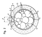
- Fig. 2 shows in cross section a cable set 13 according to the invention, the a plurality of electrical lines 11 leads and on the one according to the invention Positioning device is clamped, which has an annular, with a slot 25 provided carrier 15 and one on the radial
- the outside of the carrier 15 is arranged in one piece with the carrier 15 formed holding chamber 17, in which a connecting point 19th arranged between two or more lines 11 and by clamping tabs 21 of the holding device 17 is held in a clamp-fixing manner.
- the holding chamber 17 or the holding tabs 21 are designed such that the connection point 19 even when it is off-center Arrangement held in the holding chamber 17 in a reliable manner becomes.
- the wall thickness TD of the carrier is 15 approximately 1 mm
- the radial height H of the holding chamber 17 approximately 3 mm
- the thickness d of the retaining tabs 21 is approximately 1 mm
- the holding chamber 17 has a width B of about 6 mm and is for receiving of joints 19 with a thickness between about 1 mm to 2.9 mm and a width between about 1 mm to 5.7 mm. These dimensions are only examples and can vary depending on the application vary.
- the cable set 13 is in the area of the positioning device according to the invention 15, 17 surrounded with a seal in the form of a spout 23, the by foaming the positioning device 15, 17 to the cable set 13 has been molded.
- the wall thickness of the spout 23 in the area of Holding device 17 is selected such that the holding device 17 also the material of the spout 23 covered with a covering thickness of about 2 mm is.
- the means the positioning device 15, 17 positioned and fixed connection point 19 completely embedded in the sealing spout 23 and thus optimal against external influences, especially moisture protected.
- a positioning device according to the invention only one holding device 17 are preferred Embodiments arranged several distributed in the circumferential direction Holding devices 17 are provided, e.g. is shown in Fig. 1a. In FIG. 2, the others are only for the purpose of simplifying the illustration Holding devices 17 have been omitted. Ultimately, the number depends on a support 15 provided holding devices 17 of the respective Use case.
- connection point 19 The number of individual lines 11 which are connected to a connection point 19 can be connected to one another in principle. Can also deviating from the representations in FIGS. 1a, 1b and 2, also in each case a plurality of connection points 19 by means of a single holding device 17 be fixed on the carrier 15 and thus on the cable set 13.
- 3a shows a positioning device according to the invention with a annular carrier 15 having a plurality of holding chambers 17.
- a connection point 19 wherein the two upper holding devices 17 each as passage chambers are formed and a total of six lines 11, each of which three are introduced from one side, connecting with each other Fix the connection point 19, while the lower one, which serves as the end chamber Holding device 17 a connection point between three of only one side led lines 11 fixed.
- the remaining cable set is on in FIG. 3a the positioning device according to the invention with the ring carrier 15 is plugged on, not shown.
- the carrier 15 and the holding devices 17 are not in one piece formed with each other, but the holding devices 17 are provided in the form of separate components, which are coupled to the carrier 15 can be, the connection provided for this principle in any way and e.g. as plug-in, snap-in or clip connection can be designed.
- This modular structure of the positioning device allows only the required number of Holding devices 17 need to be coupled to the carrier 15.
- FIG. 3b shows the finished cable set 13, to which a sealing sleeve 23 is molded which is the positioning device shown in FIG. 3a completely surrounds and thereby the individual connection points 19 perfectly protects against external influences such as moisture.
- the individual lines 11 through the three means the positioning device 15, 17 on the cable set 13 fixed connection points 19 are connected to each other, protruding from the cable set 13 shown. Basically, the diversion or integration these lines 11 each at an arbitrary distance from the sealing spout 23 take place.
- the sealing sleeve 23 is used for the sealing implementation of the cable set 13 through a passage opening in a motor vehicle component, e.g. through a vehicle front wall separating the vehicle interior from the engine compartment.
- the sealing sleeve 23 advantageously fulfills one Double function by keeping the drying area away from moisture Wet area protects and at the same time for the sealing of the connection points 19 worries.
- connection points 19 For sealing the connection points 19 and thus for the production of a cable set according to the invention - cf. in particular Fig. 3a and 3b - first of all the required connecting points 19 between the lines 11 e.g. by ultrasonic welding, resistance welding or crimped. Then the connection points 17 in the holding devices 17 of the invention Positioning device fixed. Attaching the carrier 15 to the Cable set 13 and - with a modular structure - assembly the positioning device by coupling the holding devices 17 with the carrier 15 can either before or after the manufacture of the Junctions 19 take place.
- connection points 19 by means of the positioning device on Cable set 13 are fixed, the positioning device is foamed around to produce a seal 23 with the required external shape.
- the preferred embodiment of the positioning device according to the invention with holding devices projecting radially from an annular carrier 15 17 ensures an intimate positive and non-positive Connection between the positioning device 15, 17 and the seal 23rd
Abstract
Description
Die Erfindung betrifft eine Positioniereinrichtung für Leitungen in Kabelsätzen. Die Erfindung betrifft ferner ein Verfahren zum Abdichten von Verbindungsstellen, die jeweils zwischen mehreren Leitungen eines Kabelsatzes hergestellt werden.The invention relates to a positioning device for lines in cable sets. The invention further relates to a method for sealing Connection points, each between several lines of a cable set getting produced.
Insbesondere bei der Herstellung von Kraftfahrzeugen werden elektrische Leitungen, die zur Stromversorgung von Bauteilen sowie zur Signalübertragung dienen, als Kabelsätze oder Kabelbäume verlegt, in denen eine Vielzahl von elektrischen Leitungen zu einem Bündel zusammengefasst sind. Um bestimmte Signale oder elektrische Potentiale an unterschiedlichen Orten im Kraftfahrzeug zur Verfügung zu stellen, ist es erforderlich, dass mehrere Leitungen des Kabelsatzes miteinander verbunden werden und an bestimmten Positionen längs des Kabelsatzes Leitungen jeweils vom Kabelsatz weggeführt oder in den Kabelsatz aufgenommen werden. Beispielsweise wird ein die Fahrzeuggeschwindigkeit repräsentierendes Signal, das an einem Ort im Fahrzeug erzeugt wird, an mehreren räumlich voneinander getrennten Orten im Fahrzeug benötigt. Hierzu muss die das Geschwindigkeitssignal führende Leitung zum einen in den Fahrzeugkabelsatz eingegliedert und zum anderen mit einer oder mehreren Leitungen verbunden werden, die jeweils an einer entfernten Position vom Kabelsatz abzweigen, um das Signal dem jeweiligen Bauteil zuzuführen. Eine Verbindungsstelle, an der zwei oder mehr Leitungen miteinander verbunden werden, wird auch als "splice" bezeichnet. Especially in the manufacture of motor vehicles, electrical Cables used to power components and for signal transmission serve as cable sets or wiring harnesses in which one Large number of electrical cables combined into a bundle are. To certain signals or electrical potentials at different To make it available to locations in the motor vehicle, it is necessary that several lines of the cable set are connected to each other and lines at specific positions along the harness led away from the cable set or included in the cable set. For example, one that represents the vehicle speed Signal that is generated at one location in the vehicle, spatially at several separate locations in the vehicle. To do this, the Speed signal leading line on the one hand in the vehicle cable set integrated and the other with one or more lines connected, each at a remote position from the cable set branch to feed the signal to the respective component. A liaison office on which two or more lines are connected are also referred to as "splice".
Da Kabelsätze auch in Nassbereichen wie beispielsweise dem Motorraum eines Fahrzeugs verlegt werden müssen, kommt der Abdichtung der Verbindungsstellen zwischen den Leitungen eine besondere Bedeutung zu. Bekannte Lösungen, die spezielle Abdichtröhren, Schrumpfschläuche oder einfach handelsübliche Klebebänder zum Abdichten der Verbindungsstellen verwenden, sind zeitaufwändig und kostenintensiv, da sie zum einen mit einem hohen Materialverbrauch verbunden sind und zum anderen jede einzelne Verbindungsstelle getrennt von den anderen Verbindungsstellen abgedichtet werden muss. Ferner ist bei den bekannten Lösungen von Nachteil, dass die Relativpositionen der einzelnen Verbindungsstellen undefiniert sind und die gegenseitige Isolierung der Verbindungsstellen nicht mit ausreichender Zuverlässigkeit sichergestellt werden kann, was insgesamt zu einer geringen Prozesssicherheit sowie dazu führt, dass auch aufgrund der schwierigen Handhabung der bekannten Lösungen bei der Montage von Kabelsätzen ein hoher Aufwand betrieben werden muss.Because cable sets also in wet areas such as the engine compartment a vehicle must be relocated, comes the sealing of the connection points between the lines of particular importance. Known solutions that special sealing tubes, heat shrink tubing or Simply commercially available adhesive tapes for sealing the connection points use are time-consuming and costly because, on the one hand are associated with high material consumption and secondly each individual connection point separate from the other connection points must be sealed. Furthermore, the known solutions disadvantageous that the relative positions of the individual connection points are undefined and the mutual isolation of the connection points what can not be ensured with sufficient reliability overall, low process reliability as well as that due to the difficult handling of the known solutions at Assembly of cable sets requires a lot of effort.
Aufgabe der Erfindung ist es, eine Möglichkeit zu schaffen, die Herstellung von Kabelsätzen und insbesondere die Abdichtung von Verbindungsstellen zwischen mehreren Leitungen des Kabelsatzes zu vereinfachen, wobei insbesondere ein möglichst hohes Maß an Prozesssicherheit gewährleistet sein soll und die Herstellungs- und Montagekosten minimiert werden sollen.The object of the invention is to provide a way to manufacture of cable sets and in particular the sealing of connection points to simplify between several lines of the cable set, wherein In particular, the highest possible level of process security is guaranteed should be and the manufacturing and assembly costs are minimized should.
Die Lösung dieser Aufgabe erfolgt zum einen durch die Merkmale des unabhängigen Vorrichtungsanspruchs 1 und insbesondere dadurch, dass die Positioniereinrichtung wenigstens einen an einem Kabelsatz fixierbaren Träger umfasst, der zumindest eine Halteeinrichtung aufweist, mit der wenigstens eine zwischen mehreren Leitungen des Kabelsatzes hergestellte Verbindungsstelle in einer vorgegebenen Position am Träger fixierbar ist.This problem is solved on the one hand by the features of independent device claim 1 and in particular in that the positioning device at least one fixable on a cable set Carrier comprises, which has at least one holding device with which at least one made between several lines of the cable set Connection point can be fixed in a predetermined position on the carrier is.
Die Erfindung stellt eine Positioniereinrichtung bereit, mit der die einzelnen Verbindungsstellen jeweils in einer vorgegebenen Position relativ zum Kabelsatz fixiert werden können, indem der Träger der Positioniereinrichtung am Kabelsatz befestigt und die zu positionierende Verbindungsstelle an der Halteeinrichtung des Trägers fixiert wird.The invention provides a positioning device with which the individual Connection points each in a predetermined position relative to Cable set can be fixed by the support of the positioning device attached to the cable set and the connection point to be positioned is fixed to the holding device of the carrier.
Von besonderem Vorteil ist, dass erfindungsgemäß die Positionierung des Trägers und damit der Verbindungsstellen ohne zusätzliche Befestigungsmittel alleine unter Verwendung der erfindungsgemäßen Positioniereinrichtung möglich ist.It is particularly advantageous that the positioning of the Carrier and thus the connection points without additional fasteners alone using the positioning device according to the invention is possible.
Vorzugsweise weist der Träger mehrere Halteeinrichtungen auf, die gegeneinander isoliert und insbesondere räumlich voneinander getrennt sind. Auf diese Weise können mit lediglich einer Vorrichtung mehrere Verbindungsstellen in definierten Relativpositionen zueinander am Kabelsatz positioniert werden, wobei eine gegenseitige Isolierung der Verbindungsstellen durch die Ausgestaltung der Positioniereinrichtung gewährleistet ist.The carrier preferably has a plurality of holding devices, which act against one another are isolated and in particular spatially separated. In this way, several connection points can be made with just one device in defined relative positions to each other on the cable set be positioned, with mutual isolation of the Connection points through the design of the positioning device is guaranteed.
Eine besonders einfache Handhabbarkeit wird erreicht, wenn gemäß einer besonders bevorzugten Ausführungsform der Erfindung der Träger am Kabelsatz festklemmbar ist. Der Träger kann als auf den Kabelsatz steckbarer Reiter ausgebildet sein. A particularly simple handling is achieved if according to one particularly preferred embodiment of the invention of the carrier on Cable set can be clamped. The carrier can be plugged onto the cable set Be trained riders.
In einer weiteren besonders bevorzugten Ausgestaltung der Erfindung ist der Träger ringförmig ausgebildet. Dabei kann der Träger als offener und insbesondere geschlitzter Ring vorgesehen sein. Hierdurch kann die Positioniereinrichtung auf denkbar einfache Weise über den Kabelsatz geschoben bzw. auf den Kabelsatz aufgesteckt werden.In a further particularly preferred embodiment of the invention the carrier is annular. The carrier can be as open and in particular slotted ring can be provided. This allows the positioning device pushed in a very simple way over the cable set or be plugged onto the cable set.
Der Durchmesser des ringförmigen Trägers ist vorzugsweise derart an die Abmessungen des jeweiligen Kabelsatzes angepasst, dass ein sicherer, gegen axiale Relativbewegungen gesicherter Klemmsitz der Positioniereinrichtung auf dem Kabelsatz gewährleistet ist.The diameter of the ring-shaped carrier is preferably such that Dimensions of the respective cable set adapted that a safe, clamping position of the positioning device secured against axial relative movements on the cable set is guaranteed.
Des Weiteren wird vorgeschlagen, dass die Halteeinrichtung - bei am Kabelsatz fixiertem Träger - auf einer radial vom Kabelsatz weg weisenden Außenseite des Trägers angeordnet ist.Furthermore, it is proposed that the holding device - at on Cable set fixed carrier - on a radially facing away from the cable set Outside of the carrier is arranged.
Wenn der Träger mehrere Halteeinrichtungen aufweist, ist bevorzugt vorgesehen, dass die Halteeinrichtungen in Umfangsrichtung des Trägers verteilt angeordnet sind. Auf diese Weise kann eine besonders vorteilhafte, stern- oder radförmige Ausgestaltung der Positioniereinrichtung realisiert werden, bei der die Halteeinrichtungen auf der Außenseite des Trägers angeordnet sind und sich - bei am Kabelsatz fixiertem Träger - vom Kabelsatz weg erstrecken bzw. vom Kabelsatz weg weisen. Hierdurch wird bei minimalem Platzbedarf für die erfindungsgemäße Positioniereinrichtung eine sichere und zuverlässige Positionierung sowie gegenseitige Isolierung der einzelnen Verbindungsstellen erzielt.If the carrier has several holding devices, it is preferred provided that the holding devices in the circumferential direction of the carrier are distributed. In this way, a particularly advantageous Star or wheel-shaped configuration of the positioning device realized in which the holding devices on the outside of the carrier are arranged and - with the bracket fixed to the cable set - from the cable set extend away or point away from the cable set. This will help minimal space requirement for the positioning device according to the invention safe and reliable positioning and mutual isolation of the individual connection points achieved.
Gemäß einer weiteren bevorzugten Ausgestaltung der Erfindung ist die Halteeinrichtung derart ausgebildet, dass die Verbindungsstelle an der Halteeinrichtung festgeklemmt werden kann. Auf zusätzliche Befestigungsmittel zur Fixierung der Verbindungsstellen an der Positioniereinrichtung und damit am Kabelsatz kann somit in vorteilhafter Weise verzichtet werden.According to a further preferred embodiment of the invention Holding device formed such that the connection point on the Holding device can be clamped. On additional fasteners for fixing the connection points to the positioning device and thus on the cable set can thus be dispensed with in an advantageous manner become.
Ferner ist vorzugsweise vorgesehen, dass die Halteeinrichtung als in axialer Richtung zumindest einseitig offene Haltekammer zur Aufnahme der Verbindungsstelle ausgebildet ist. Die Haltekammer kann als Klemmkammer ausgebildet sein, in der die jeweilige Verbindungsstelle festgeklemmt werden kann.Furthermore, it is preferably provided that the holding device as in Axial direction at least one side open holding chamber for receiving the connection point is formed. The holding chamber can be used as a clamping chamber be formed in which the respective connection point is clamped can be.
Hierzu kann die Haltekammer wenigstens eine elastisch auslenkbare Haltelasche aufweisen, die durch Einführen der Verbindungsstelle in die Haltekammer nach innen wegdrückbar ist und die eine in der Haltekammer positionierte Verbindungsstelle klemmfixierend beaufschlagt. Die Verbindungsstelle braucht somit lediglich in die Haltekammer eingedrückt zu werden, wobei dies zumindest prinzipiell sowohl vor als auch nach der Befestigung des Trägers am Kabelsatz erfolgen kann.For this purpose, the holding chamber can be at least one elastically deflectable Have retaining tab, which by inserting the connection point in the Holding chamber is pushed inwards and the one in the holding chamber positioned connection point is clamped. The Connection point thus only needs to be pressed into the holding chamber to be, at least in principle both before and after the Attachment of the carrier to the cable set can be done.
In einer bevorzugten Ausführungsform weist die Positioniereinrichtung im Bereich der Halteeinrichtung eine radiale Stärke von weniger als 10 mm, bevorzugt von weniger als 5 mm und insbesondere bevorzugt von etwa 3 bis 4 mm auf. Die radiale Wanddicke des Trägers beträgt bevorzugt etwa 1 mm. Die Halteeinrichtung weist vorzugsweise eine radiale Höhe von etwa 2 bis 4 mm und bevorzugt von etwa 3 mm auf. In a preferred embodiment, the positioning device in the Area of the holding device a radial thickness of less than 10 mm, preferably less than 5 mm and particularly preferably about 3 up to 4 mm. The radial wall thickness of the carrier is preferably about 1 mm. The holding device preferably has a radial height of approximately 2 to 4 mm and preferably from about 3 mm.
Hierdurch werden der Materialverbrauch für die Positionierung der Verbindungsstellen sowie das Gewicht und die radialen Abmessungen des Kabelsatzes minimiert.As a result, the material consumption for the positioning of the connection points as well as the weight and radial dimensions of the Cable set minimized.
Des Weiteren ist es gemäß einer Ausführungsform der Erfindung bevorzugt, dass die Positioniereinrichtung einstückig ausgebildet ist. Alternativ können die Halteeinrichtung einerseits und der Träger andererseits als separate und miteinander koppelbare Bauteile vorgesehen sein, wobei die Art und Weise der Kopplung grundsätzlich beliebig und z.B. als Rast-, Steck- oder Clipsverbindung ausgestaltet sein kann. Das bevorzugte Material für die Positioniereinrichtung ist Kunststoff.Furthermore, according to one embodiment of the invention, it is preferred that the positioning device is formed in one piece. alternative can the holding device on the one hand and the carrier on the other hand as separate and interconnectable components can be provided, the The type of coupling is basically arbitrary and e.g. as rest, Plug or clip connection can be designed. The preferred material for the positioning device is plastic.
Die der Erfindung zugrunde liegende Aufgabe wird zum anderen durch ein Verfahren mit den Merkmalen des unabhängigen Verfahrensanspruchs 23 und insbesondere dadurch gelöst, dass zumindest eine zwischen mehreren Leitungen des Kabelsatzes gebildete Verbindungsstelle am Kabelsatz fixiert wird, und dass der Kabelsatz im Bereich der Verbindungsstelle derart mit einer Abdichtung versehen wird, dass die am Kabelsatz fixierte Verbindungsstelle vollständig von der Abdichtung umgeben und insbesondere in die Abdichtung eingebettet ist.The object underlying the invention is, on the other hand, by a Process with the features of independent process claim 23 and in particular solved in that at least one between several Lines of the cable set formed connection point on the cable set is fixed, and that the cable set in the area of the connection point is provided with a seal so that it is fixed to the cable set Connection point completely surrounded by the seal and in particular is embedded in the seal.
Erfindungsgemäß wird eine entsprechend dem jeweiligen Anwendungszweck ausgebildete Abdichtung dazu genutzt, gleichzeitig die Verbindungsstelle optimal vor äußeren Einflüssen wie insbesondere Feuchtigkeit zu schützen. Der Kabelsatz braucht lediglich derart ausgelegt zu werden, dass die Verbindungsstelle an eine Position längs des Kabelsatzes gelegt werden kann, an der die Abdichtung benötigt wird. Zusätzlich zu dem ohnehin erforderlichen Vorsehen der Abdichtung braucht erfindungsgemäß lediglich die Verbindungsstelle am Kabelsatz fixiert zu werden.According to the invention is a corresponding to the respective application trained seal used at the same time the connection point optimal against external influences such as moisture to protect. The cable set only needs to be designed in such a way that the junction is placed at a location along the harness where the seal is needed. In addition to that anyway necessary provision of the seal needs according to the invention only the connection point to be fixed on the cable set.
Die Fixierung der Verbindungsstelle am Kabelsatz erfolgt beispielsweise einfach durch ein herkömmliches Klebeband. Diese Variante ist besonders vorteilhaft in Fällen, in denen an einer bestimmten Position oder in einem bestimmten Bereich längs des Kabelsatzes lediglich eine einzige Verbindungsstelle vorhanden ist, da dann auf die Relativpositionen mehrerer Verbindungsstellen untereinander nicht geachtet zu werden braucht.The connection point is fixed to the cable set, for example simply with a conventional adhesive tape. This variant is special advantageous in cases where in a certain position or in a certain area along the cable set only a single connection point is available because then on the relative positions of several There is no need to pay attention to the connection points.
Gemäß einer besonders bevorzugten Ausführung des erfindungsgemäßen Verfahrens ist vorgesehen, dass wenigstens ein Träger am Kabelsatz fixiert wird, dass die vor oder nach dem Fixieren des Trägers am Kabelsatz hergestellte Verbindungsstelle mittels einer Halteeinrichtung des Trägers in einer vorgegebenen Position am Träger fixiert wird, und dass der Kabelsatz im Bereich der Halteeinrichtung derart mit der Abdichtung versehen wird, dass zumindest die am Träger fixierte Verbindungsstelle vollständig von der Abdichtung umgeben und insbesondere in die Abdichtung eingebettet ist.According to a particularly preferred embodiment of the invention The method provides that at least one carrier is fixed to the cable set is that the one made before or after fixing the bracket to the harness Connection point by means of a holding device of the carrier in a predetermined position on the carrier is fixed, and that the cable set is provided with the seal in the area of the holding device, that at least the connection point fixed to the carrier is completely from surround the seal and in particular embedded in the seal is.
Hierbei erfolgt die Abdichtung der Verbindungsstellen dadurch, dass die Verbindungsstellen zunächst mittels eines am Kabelsatz fixierbaren Trägers sowie einer Halteeinrichtung des Trägers in einer vorgegebenen Position relativ zum Kabelsatz fixiert werden und anschließend die Anordnung aus Kabelsatz, Träger, Halteeinrichtung sowie Verbindungsstelle mit der Abdichtung versehen wird. The joints are sealed by the fact that the Connection points first by means of a bracket that can be fixed to the cable set and a holding device of the carrier in a predetermined position be fixed relative to the cable set and then the arrangement from cable set, bracket, holding device and connection point with the Sealing is provided.
In einer besonders bevorzugten Ausführung des erfindungsgemäßen Verfahrens
wird die Abdichtung durch Umschäumen der insbesondere mittels
einer Halteeinrichtung eines am Kabelsatz fixierten Trägers fixierten Verbindungsstelle
an den Kabelsatz angeformt. Bevorzugt wird die Abdichtung
als Tülle, Durchführung, Stopfen, Röhre oder Hülse ausgebildet.
Eine derartige Abdichtung wird auch als "grommet" bezeichnet.In a particularly preferred embodiment of the method according to the invention, the seal is molded onto the cable set by foaming the connection point, which is fixed in particular by means of a holding device of a carrier fixed to the cable set. The seal is preferably designed as a spout, bushing, plug, tube or sleeve.
Such a seal is also called "grommet".
Hierdurch macht sich die Erfindung in vorteilhafter Weise den Umstand zu Nutzen, dass insbesondere im Bereich des Fahrzeugbaus in Verbindung mit Kabelsätzen bzw. Kabelbäumen zunehmend geschäumte Abdichtungen insbesondere in Form von Tüllen, Durchführungen, Stopfen, Röhren oder Hülsen verwendet werden, um Durchgangsöffnungen in Bauteilen des Fahrzeugs, durch welche der Kabelsatz bzw. Kabelbaum hindurchgeführt werden muss, gegen den Durchtritt von Feuchtigkeit und anderen äußeren Einflüssen abzudichten. Übergänge zwischen Nassbereichen und Trockenbereichen eines Fahrzeugs sind beispielsweise in der Fahrzeug-Stirnwand ausgebildet, die den Fahrzeuginnenraum vom Motorraum trennt.In this way, the invention advantageously makes the circumstance to use that in particular in the field of vehicle construction increasingly foamed seals with cable sets or cable harnesses especially in the form of grommets, bushings, plugs, tubes or sleeves are used to make through holes in components of the vehicle through which the cable set or wiring harness passes against the passage of moisture and others to seal external influences. Transitions between wet areas and Dry areas of a vehicle are, for example, in the vehicle front wall trained the vehicle interior from the engine compartment separates.
Bisher befanden sich die abzudichtenden Verbindungsstellen an von den Übergängen zwischen Nass- und Trockenbereichen entfernten Positionen am Kabelsatz, so dass zur Abdichtung von insbesondere in den Nassbereichen gelegenen Verbindungsstellen spezielle, aufwändige Maßnahmen getroffen werden mussten. Erfindungsgemäß kann auf derartige Zusatzmaßnahmen verzichtet werden, wenn gemäß einer besonders bevorzugten Ausführungsform die Abdichtung gleichzeitig dasjenige Bauteil ist, mit dem der Kabelsatz durch eine Durchtrittsöffnung, die z.B. in einer Fahrzeugstirnwand ausgebildet ist, hindurchgeführt wird. Dadurch erfolgt die Abdichtung der Verbindungsstellen gewissermaßen automatisch durch eine ohnehin zum Abdichten der Durchtrittsöffnung erforderliche Abdichtung.So far, the joints to be sealed have been at the Transitions between wet and dry areas distant positions on the cable set, so that it seals especially in wet areas located, special, complex measures had to be hit. According to the invention, such additional measures can be taken be dispensed with if according to a particularly preferred one Embodiment the seal is also the component with the cable set through a passage opening that e.g. in a vehicle front wall is trained, is passed. This takes place Sealing of the connection points to a certain extent automatically a seal that is required anyway to seal the passage opening.
Die Erfindung betrifft außerdem einen Kabelsatz, der wenigstens eine erfindungsgemäße Positioniereinrichtung aufweist, wie sie beispielsweise vorstehend erläutert wurde. Ferner betrifft die Erfindung ein Verfahren zur Herstellung von Kabelsätzen, bei dem ein Abdichtverfahren zur Anwendung kommt, wie es z.B. vorstehend beschrieben wurde.The invention also relates to a cable set which has at least one has positioning device according to the invention, as for example was explained above. The invention further relates to a method for the production of cable sets in which a sealing process is used comes as it e.g. was described above.
Bevorzugte Ausführungsformen der Erfindung sind außerdem in den Ansprüchen, der Beschreibung sowie der Zeichnung angegeben.Preferred embodiments of the invention are also shown in FIGS Claims, the description and the drawing.
Die Erfindung wird im Folgenden beispielhaft unter Bezugnahme auf die Zeichnung beschrieben. Es zeigen:
- Fig. 1a
- eine Ausführungsform einer erfindungsgemäßen Positioniereinrichtung an einem Kabelsatz, wobei die Positioniereinrichtung gegenüber dem Kabelsatz stark vergrößert dargestellt ist,
- Fig. 1b
- einen vergrößerten Ausschnitt von Fig. 1a zur Erläuterung einer Halteeinrichtung der erfindungsgemäßen Positioniereinrichtung,
- Fig. 2
- schematisch im Querschnitt einen mit einer erfindungsgemäßen Positioniereinrichtung sowie einer Abdichtung versehenen Kabelsatz,
- Fig. 3a
- eine erfindungsgemäße Positioniereinrichtung mit daran fixierten Verbindungsstellen zwischen elektrischen Leitungen unter Weglassung des übrigen Kabelsatzes, und
- Fig. 3b
- einen erfindungsgemäßen Kabelsatz mit einer eine erfindungsgemäße Positioniereinrichtung umgebenden Abdichtung.
- Fig. 1a
- one embodiment of a positioning device according to the invention on a cable set, the positioning device being shown greatly enlarged compared to the cable set,
- Fig. 1b
- 1 an enlarged section of FIG. 1 a to explain a holding device of the positioning device according to the invention,
- Fig. 2
- schematically in cross section a cable set provided with a positioning device according to the invention and a seal,
- Fig. 3a
- a positioning device according to the invention with fixed connection points between electrical lines with omission of the remaining cable set, and
- Fig. 3b
- a cable set according to the invention with a seal surrounding a positioning device according to the invention.
Die Positioniereinrichtung der Erfindung gemäß Fig. 1a und 1b umfasst
einen offenen, mit einem Schlitz 25 versehenen, ringförmigen Träger 15,
der auf einem eine Vielzahl einzelner Leitungen 11 umfassenden Kabelsatz
13 eines Kraftfahrzeugs aufgesteckt ist und an seiner radial vom Kabelsatz
13 weg weisenden Außenseite mit in diesem Ausführungsbeispiel vier in
Umfangsrichtung gleichmäßig verteilt angeordneten Halteeinrichtungen
17 versehen ist. Die Positioniereinrichtung ist einstückig ausgebildet und
aus Kunststoff hergestellt.The positioning device of the invention according to FIGS. 1a and 1b comprises
an open, ring-shaped
Die Halteeinrichtungen 17 sind - vgl. insbesondere Fig. 1b - als Halteoder
Klemmkammern für Verbindungsstellen 19 ausgebildet, an denen
mehrere Leitungen 11 gleichen Potentials z.B. durch Ultraschallschweißen,
Widerstandsschweißen oder Crimpen an von der Isolierung befreiten
Endbereichen miteinander verbunden sind. Die Klemmkammern 17 sind
in axialer Richtung offen und an ihrer radial nach außen weisenden Seite
mit Haltelaschen 21 versehen. Wenn eine Verbindungsstelle 19 in radialer
Richtung von außen in die Klemmkammer 17 hineingedrückt wird, geben
die Haltelaschen 21 nach und beaufschlagen die in ihrer Sollposition in
der Klemmkammer 17 befindliche Verbindungsstelle 19 mit einer Haltekraft
derart, dass eine sichere Klemmfixierung der Verbindungsstelle 19 in
der Kammer 17 erzielt wird und die Verbindungsstelle 19 sowohl in radialer
Richtung als auch in axialer Richtung an der erfindungsgemäßen
Positioniereinrichtung und damit am Kabelsatz 13 festgehalten wird.The holding
Die obere Kammer 17 in Fig. 1a dient als sogenannte Endhaltekammer, in
welche die miteinander verbundenen Leitungen 11 lediglich von einer
Seite hineingeführt sind. Die untere Kammer 17 in Fig. 1a dient dagegen
als Durchgangskammer, in die von beiden Seiten Leitungen 11 eintreten.The
Ob eine Kammer 17 der erfindungsgemäßen Positioniereinrichtung als
End- oder Durchgangskammer dient, hängt von den jeweiligen Umständen
und dem Verlauf der miteinander zu verbindenden Leitungen 11 im
Fahrzeug und im Kabelsatz 13 ab. Die Ausgestaltung der Kammern 17
stellt sicher, dass jede Kammer 17 sowohl als End- als auch als Durchgangskammer
dienen kann, wodurch ein Höchstmaß an Flexibilität erreicht
wird.Whether a
Fig. 2 zeigt im Querschnitt einen erfindungsgemäßen Kabelsatz 13, der
eine Vielzahl von elektrischen Leitungen 11 führt und auf den eine erfindungsgemäße
Positioniereinrichtung geklemmt ist, die einen ringförmigen,
mit einem Schlitz 25 versehenen Träger 15 sowie eine auf der radialen
Außenseite des Trägers 15 angeordnete, einstückig mit dem Träger 15
ausgebildete Haltekammer 17 umfasst, in der eine Verbindungsstelle 19
zwischen zwei oder mehr Leitungen 11 angeordnet und durch Klemmlaschen
21 der Halteeinrichtung 17 klemmfixierend gehalten ist. Fig. 2 shows in cross section a cable set 13 according to the invention, the
a plurality of
Fig. 2 zeigt insbesondere, dass die Haltekammer 17 bzw. die Haltelaschen
21 derart ausgebildet sind, dass die Verbindungsstelle 19 auch bei außermittiger
Anordnung in der Haltekammer 17 in zuverlässiger Weise festgehalten
wird.2 shows in particular that the holding
In dem gezeigten Ausführungsbeispiel beträgt die Wandstärke TD des Trägers
15 etwa 1 mm, während die radiale Höhe H der Haltekammer 17 etwa
3 mm und die Stärke d der Haltelaschen 21 etwa 1 mm beträgt. Die Haltekammer
17 weist eine Breite B von etwa 6 mm auf und ist zur Aufnahme
von Verbindungsstellen 19 mit einer Dicke zwischen etwa 1 mm bis
2,9 mm sowie einer Breite zwischen etwa 1 mm bis 5,7 mm ausgelegt.
Diese Abmessungen sind lediglich beispielhaft und können je nach Anwendungsfall
variieren.In the exemplary embodiment shown, the wall thickness TD of the carrier is
15 approximately 1 mm, while the radial height H of the holding
Der Kabelsatz 13 ist im Bereich der erfindungsgemäßen Positioniereinrichtung
15, 17 mit einer Abdichtung in Form einer Tülle 23 umgeben, die
durch Umschäumen der Positioniereinrichtung 15, 17 an den Kabelsatz
13 angeformt worden ist. Die Wandstärke der Tülle 23 im Bereich der
Halteeinrichtung 17 ist derart gewählt, dass die Halteeinrichtung 17 mit
dem Material der Tülle 23 in einer Abdeckstärke von etwa 2 mm bedeckt
ist.The cable set 13 is in the area of the positioning device according to the
Auf diese Weise ist bei dem erfindungsgemäßen Kabelsatz 13 die mittels
der erfindungsgemäßen Positioniereinrichtung 15, 17 positionierte und
fixierte Verbindungsstelle 19 vollständig in die Abdichttülle 23 eingebettet
und somit optimal vor äußeren Einflüssen, insbesondere vor Feuchtigkeit,
geschützt. In this way, in the cable set 13 according to the invention, the means
the
Obwohl es grundsätzlich möglich ist, dass eine erfindungsgemäße Positioniereinrichtung
lediglich eine Halteeinrichtung 17 aufweist, sind in bevorzugten
Ausführungsformen mehrere in Umfangsrichtung verteilt angeordnete
Halteeinrichtungen 17 vorgesehen, wie es z.B. in Fig. 1a gezeigt ist.
In Fig. 2 sind lediglich zur Vereinfachung der Darstellung die übrigen
Halteeinrichtungen 17 weggelassen worden. Letztlich hängt die Zahl der
an einem Träger 15 vorgesehenen Halteeinrichtungen 17 vom jeweiligen
Anwendungsfall ab.Although it is fundamentally possible that a positioning device according to the invention
only one
Die Anzahl von einzelnen Leitungen 11, die an einer Verbindungsstelle 19
miteinander verbunden werden, ist grundsätzlich beliebig. Ferner können
abweichend von den Darstellungen in Fig. 1a, 1b und Fig. 2 auch jeweils
mehrere Verbindungsstellen 19 mittels einer einzigen Halteeinrichtung 17
am Träger 15 und damit am Kabelsatz 13 fixiert werden.The number of
Fig. 3a zeigt eine erfindungsgemäße Positioniereinrichtung mit einem
ringförmigen Träger 15, der mehrere Haltekammern 17 aufweist. In jeder
Haltekammer 17 ist eine Verbindungsstelle 19 angeordnet, wobei die
beiden oberen Halteeinrichtungen 17 jeweils als Durchgangskammern
ausgebildet sind und eine insgesamt sechs Leitungen 11, von denen jeweils
drei von einer Seite herangeführt sind, miteinander verbindende
Verbindungsstelle 19 fixieren, während die untere, als Endkammer dienende
Halteeinrichtung 17 eine Verbindungsstelle zwischen drei von
lediglich einer Seite herangeführte Leitungen 11 fixiert.3a shows a positioning device according to the invention with a
Zur Vereinfachung der Darstellung ist in Fig. 3a der übrige Kabelsatz, auf
den die erfindungsgemäße Positioniereinrichtung mit dem Ringträger 15
aufgesteckt wird, nicht gezeigt. To simplify the illustration, the remaining cable set is on in FIG. 3a
the positioning device according to the invention with the
Bei der Ausführungsform der erfindungsgemäßen Positioniereinrichtung
von Fig. 3a sind der Träger 15 und die Halteeinrichtungen 17 nicht einstückig
miteinander ausgebildet, sondern die Halteeinrichtungen 17 sind
in Form von separaten Bauteilen vorgesehen, die mit dem Träger 15 gekoppelt
werden können, wobei die hierfür vorgesehene Verbindung grundsätzlich
in beliebiger Art und Weise und z.B. als Steck-, Rast- oder ClipsVerbindung
ausgestaltet sein kann. Dieser modulare Aufbau der Positioniereinrichtung
gestattet es, dass jeweils nur die benötigte Anzahl von
Halteeinrichtungen 17 mit dem Träger 15 gekoppelt zu werden braucht.In the embodiment of the positioning device according to the invention
3a, the
Fig. 3b zeigt den fertigen Kabelsatz 13, an den eine Abdichttülle 23 angeformt
ist, welche die in Fig. 3a gezeigte Positioniereinrichtung vollständig
umgibt und dadurch die einzelnen Verbindungsstellen 19 perfekt vor
äußeren Einflüssen wie insbesondere Feuchtigkeit schützt. Zur Verdeutlichung
sind in Fig. 3b die einzelnen Leitungen 11, die durch die drei mittels
der Positioniereinrichtung 15, 17 am Kabelsatz 13 fixierten Verbindungsstellen
19 miteinander verbunden werden, vom Kabelsatz 13 abstehend
gezeigt. Grundsätzlich kann die Abzweigung bzw. Eingliederung
dieser Leitungen 11 jeweils in einer beliebigen Entfernung von der Abdichttülle
23 erfolgen.3b shows the finished cable set 13, to which a sealing
Die Abdichttülle 23 dient zur abdichtenden Durchführung des Kabelsatzes
13 durch eine Durchtrittsöffnung in einem Kraftfahrzeugbauteil, z.B.
durch eine den Fahrzeuginnenraum vom Motorraum trennende Fahrzeugstirnwand.
Hierdurch erfüllt die Abdichttülle 23 in vorteilhafter Weise eine
Doppelfunktion, indem sie den Trockenbereich vor Feuchtigkeit aus dem
Nassbereich schützt und gleichzeitig für die Abdichtung der Verbindungsstellen
19 sorgt.The sealing
Zum Abdichten der Verbindungsstellen 19 und somit zur Herstellung
eines erfindungsgemäßen Kabelsatzes werden - vgl. insbesondere Fig. 3a
und 3b - zunächst die jeweils erforderlichen Verbindungsstellen 19 zwischen
den Leitungen 11 z.B. durch Ultraschallschweißen, Widerstandsschweißen
oder Crimpen hergestellt. Anschließend werden die Verbindungsstellen
17 in den Halteeinrichtungen 17 der erfindungsgemäßen
Positioniereinrichtung fixiert. Das Aufstecken des Trägers 15 auf den
Kabelsatz 13 sowie - bei einem modularen Aufbau - das Zusammensetzen
der Positioniereinrichtung durch Koppeln der Halteeinrichtungen 17 mit
dem Träger 15 kann dabei entweder vor oder nach der Herstellung der
Verbindungsstellen 19 erfolgen.For sealing the connection points 19 and thus for the production
of a cable set according to the invention - cf. in particular Fig. 3a
and 3b - first of all the required connecting
Wenn die Verbindungsstellen 19 mittels der Positioniereinrichtung am
Kabelsatz 13 fixiert sind, wird die Positioniereinrichtung umschäumt, um
eine Abdichtung 23 mit der jeweils erforderlichen äußeren Form herzustellen.
Die bevorzugte Ausgestaltung der erfindungsgemäßen Positioniereinrichtung
mit radial von einem ringförmigen Träger 15 abstehenden Halteeinrichtungen
17 sorgt dabei für eine innige form- und kraftschlüssige
Verbindung zwischen der Positioniereinrichtung 15, 17 und der Abdichtung
23. If the connection points 19 by means of the positioning device on
Cable set 13 are fixed, the positioning device is foamed around
to produce a
- 1111
- Leitungmanagement
- 1313
- Kabelsatzcableset
- 1515
- Trägercarrier
- 1717
- Halteeinrichtungholder
- 1919
- Verbindungsstelle, SpliceLiaison Office, Splice
- 2121
- Haltelascheretaining tab
- 2323
- Abdichtungseal
- 2525
- Schlitzslot
- TDTD
- Wanddicke des TrägersWall thickness of the beam
- HH
- Höhe der HalteeinrichtungHeight of the holding device
- dd
- Stärke der HaltelaschenThickness of the retaining tabs
- BB
- Breite der HalteeinrichtungWidth of the holding device
- AA
- AbdeckstärkeAbdeckstärke
Claims (29)
dadurch gekennzeichnet, dass der Träger (15) am Kabelsatz (13) festklemmbar ist.Positioning device according to claim 1,
characterized in that the carrier (15) can be clamped to the cable set (13).
dadurch gekennzeichnet, dass der Träger (15) als auf dem Kabelsatz (13) steckbarer Reiter ausgebildet ist.Positioning device according to claim 1 or 2,
characterized in that the carrier (15) is designed as a tab that can be plugged onto the cable set (13).
dadurch gekennzeichnet, dass der Träger (15) ringförmig ausgebildet ist.Positioning device according to one of the preceding claims,
characterized in that the carrier (15) is annular.
dadurch gekennzeichnet, dass der Träger (15) als offener und insbesondere geschlitzter Ring ausgebildet ist. Positioning device according to one of the preceding claims,
characterized in that the carrier (15) is designed as an open and in particular slotted ring.
dadurch gekennzeichnet, dass die Halteeinrichtung (17) einstückig mit dem Träger (15) ausgebildet ist.Positioning device according to one of the preceding claims,
characterized in that the holding device (17) is formed in one piece with the carrier (15).
dadurch gekennzeichnet, dass die Halteeinrichtung (17) einerseits und der Träger (15) andererseits als separate und miteinander koppelbare Bauteile vorgesehen sind.Positioning device according to one of claims 1 to 5,
characterized in that the holding device (17) on the one hand and the carrier (15) on the other hand are provided as separate components which can be coupled together.
dadurch gekennzeichnet, dass die Halteeinrichtung (17) bei am Kabelsatz (13) fixiertem Träger (15) auf einer radial vom Kabelsatz (13) weg weisenden Außenseite des Trägers (15) angeordnet ist.Positioning device according to one of the preceding claims,
characterized in that the holding device (17), when the carrier (15) is fixed to the cable set (13), is arranged on an outside of the carrier (15) pointing radially away from the cable set (13).
dadurch gekennzeichnet, dass der Träger (15) mehrere gegeneinander isolierte und insbesondere räumlich voneinander getrennte Halteeinrichtungen (17) aufweist.Positioning device according to one of the preceding claims,
characterized in that the carrier (15) has a plurality of holding devices (17) which are insulated from one another and in particular spatially separated from one another.
dadurch gekennzeichnet, dass die Halteeinrichtungen (17) in Umfangsrichtung des Trägers (15) verteilt angeordnet sind. Positioning device according to claim 9,
characterized in that the holding devices (17) are arranged distributed in the circumferential direction of the carrier (15).
dadurch gekennzeichnet, dass sie stern- oder radförmig mit bei am Kabelsatz (13) fixiertem Träger (15) vom Kabelsatz (13) weg weisenden Halteeinrichtungen (17) ausgebildet ist.Positioning device according to one of the preceding claims,
characterized in that it is star-shaped or wheel-shaped with holding devices (17) pointing away from the cable set (13) when the carrier (15) is fixed to the cable set (13).
dadurch gekennzeichnet, dass die Verbindungsstelle (19) an der Halteeinrichtung (17) festklemmbar ist.Positioning device according to one of the preceding claims,
characterized in that the connection point (19) can be clamped on the holding device (17).
dadurch gekennzeichnet, dass die Halteeinrichtung (17) als in axialer Richtung zumindest einseitig offene Haltekammer zur Aufnahme der Verbindungsstelle (19) ausgebildet ist.Positioning device according to one of the preceding claims,
characterized in that the holding device (17) is designed as a holding chamber open at least on one side in the axial direction for receiving the connection point (19).
dadurch gekennzeichnet, dass die Haltekammer (17) wenigstens eine elastisch auslenkbare Haltelasche (21) aufweist, die durch Einführen der Verbindungsstelle (19) in die Haltekammer (17) nach innen wegdrückbar ist und die eine in der Haltekammer (17) positionierte Verbindungsstelle (19) klemmfixierend beaufschlagt. Positioning device according to claim 13,
characterized in that the holding chamber (17) has at least one elastically deflectable holding tab (21) which can be pushed inwards by inserting the connecting point (19) into the holding chamber (17) and which has a connecting point (19) positioned in the holding chamber (17) ) acted to fix the clamp.
dadurch gekennzeichnet, dass sie im Bereich der Halteeinrichtung (17) eine radiale Stärke von weniger als 10 mm, bevorzug von weniger als 5 mm und insbesondere bevorzugt von etwa 3 bis 4 mm aufweist.Positioning device according to one of the preceding claims,
characterized in that it has a radial thickness of less than 10 mm, preferably less than 5 mm and particularly preferably about 3 to 4 mm in the area of the holding device (17).
dadurch gekennzeichnet, dass der Träger (15) eine radiale Wanddicke von etwa 1 mm aufweist.Positioning device according to one of the preceding claims,
characterized in that the carrier (15) has a radial wall thickness of approximately 1 mm.
dadurch gekennzeichnet, dass die Halteeinrichtung (17) eine radiale Höhe von etwa 2 bis 4 mm und bevorzugt von etwa 3 mm aufweist.Positioning device according to one of the preceding claims,
characterized in that the holding device (17) has a radial height of approximately 2 to 4 mm and preferably approximately 3 mm.
dadurch gekennzeichnet, dass sie einstückig ausgebildet und insbesondere aus Kunststoff hergestellt ist.Positioning device according to one of the preceding claims,
characterized in that it is formed in one piece and in particular is made of plastic.
dadurch gekennzeichnet, dass er im Bereich der Positioniereinrichtung (15, 17) mit einer Abdichtung (23) insbesondere in Form einer Tülle, einer Durchführung, eines Stopfens, einer Röhre oder einer Hülse versehen ist. Cable set according to claim 19,
characterized in that it is provided in the region of the positioning device (15, 17) with a seal (23), in particular in the form of a spout, a bushing, a plug, a tube or a sleeve.
dadurch gekennzeichnet, dass zumindest die Halteeinrichtung (17) der Positioniereinrichtung (15, 17) vollständig von der Abdichtung (23) umgeben und insbesondere in die Abdichtung (23) eingebettet ist.Cable set according to claim 20,
characterized in that at least the holding device (17) of the positioning device (15, 17) is completely surrounded by the seal (23) and in particular is embedded in the seal (23).
dadurch gekennzeichnet, dass die Abdichtung (23) durch Umschäumen zumindest eines Teils der Positioniereinrichtung (15, 17) hergestellt ist.Cable set according to claim 20 or 21,
characterized in that the seal (23) is produced by foaming at least part of the positioning device (15, 17).
dadurch gekennzeichnet,
characterized,
dadurch gekennzeichnet, dass die Abdichtung (23) durch Umschäumen der Verbindungsstelle (19), insbesondere der mittels einer Halteeinrichtung (17) eines am Kabelsatz (13) fixierten Trägers (15) fixierten Verbindungsstelle (19), an den Kabelsatz (13) angeformt wird.A method according to claim 23 or 24,
characterized in that the seal (23) is molded onto the cable set (13) by foaming the connection point (19), in particular the connection point (19) fixed by means of a holding device (17) of a carrier (15) fixed to the cable set (13) ,
dadurch gekennzeichnet, dass die Abdichtung (23) als Tülle, Durchführung, Stopfen, Röhre oder Hülse ausgebildet wird. Method according to one of claims 23 to 25,
characterized in that the seal (23) is designed as a spout, bushing, plug, tube or sleeve.
dadurch gekennzeichnet, dass die Verbindungsstelle (19) zwischen den Leitungen (11) durch Ultraschallschweißen, Widerstandsschweißen oder Crimpen hergestellt wird.Method according to one of claims 23 to 26,
characterized in that the connection point (19) between the lines (11) is produced by ultrasonic welding, resistance welding or crimping.
dadurch gekennzeichnet, dass zum Fixieren der Verbindungsstelle (19) eine wenigstens einen Träger (15) und zumindest eine Halteeinrichtung (17) aufweisende Positioniereinrichtung nach einem der Ansprüche 1 bis 18 verwendet wird.Method according to one of claims 23 to 27,
characterized in that a positioning device according to one of claims 1 to 18 having at least one support (15) and at least one holding device (17) is used to fix the connection point (19).
Applications Claiming Priority (2)
| Application Number | Priority Date | Filing Date | Title |
|---|---|---|---|
| DE2002105328 DE10205328A1 (en) | 2002-02-08 | 2002-02-08 | positioning |
| DE10205328 | 2002-02-08 |
Publications (2)
| Publication Number | Publication Date |
|---|---|
| EP1335463A2 true EP1335463A2 (en) | 2003-08-13 |
| EP1335463A3 EP1335463A3 (en) | 2004-08-25 |
Family
ID=27588503
Family Applications (1)
| Application Number | Title | Priority Date | Filing Date |
|---|---|---|---|
| EP03002470A Withdrawn EP1335463A3 (en) | 2002-02-08 | 2003-02-05 | Positionning device |
Country Status (2)
| Country | Link |
|---|---|
| EP (1) | EP1335463A3 (en) |
| DE (1) | DE10205328A1 (en) |
Cited By (2)
| Publication number | Priority date | Publication date | Assignee | Title |
|---|---|---|---|---|
| WO2007017332A1 (en) * | 2005-08-05 | 2007-02-15 | Tesa Ag | Adhesive tape comprising a spunbonded backing one-sidedly coated at least partially with a fibre-filled pressure-sensitive adhesive |
| CN101559748B (en) * | 2008-04-15 | 2012-10-24 | 通用汽车环球科技运作公司 | High-voltage vehicle component connection method and apparatus |
Citations (4)
| Publication number | Priority date | Publication date | Assignee | Title |
|---|---|---|---|---|
| WO1992009089A1 (en) * | 1990-11-05 | 1992-05-29 | United Technologies Automotive, Inc. | Wire harness assembly with routing sleeve |
| DE19911415A1 (en) * | 1999-03-15 | 2000-05-18 | Siemens Ag | Cable connection device for unbared round cable contacting |
| DE20103762U1 (en) * | 2001-03-03 | 2001-06-07 | Sihn Jr Kg Wilhelm | Grounded cable fitting |
| EP1177951A2 (en) * | 2000-08-02 | 2002-02-06 | Honda Giken Kogyo Kabushiki Kaisha | Wire harness structure |
Family Cites Families (6)
| Publication number | Priority date | Publication date | Assignee | Title |
|---|---|---|---|---|
| DE3528130A1 (en) * | 1985-08-06 | 1987-02-12 | Kabel & Lackdrahtfab Gmbh | Pre-prepared fittings for a screened, plastic-insulated power cable |
| IT1245585B (en) * | 1991-03-25 | 1994-09-29 | Giuseppe Codrino | OPERATING PROCEDURE, TO ALLOW THE APPLICATION OF WATERPROOF STRUCTURES, ON CONTINUOUS PROTECTIVE SHEATS, FOR COATING OF ELECTRIC WIRING CABLES |
| DE4240171C2 (en) * | 1992-11-30 | 2001-08-02 | Abb Patent Gmbh | Splice housing for a power cable with integrated optical fibers |
| DE4309538A1 (en) * | 1993-03-24 | 1994-09-29 | Rheydt Kabelwerk Ag | Branching device |
| DE29516216U1 (en) * | 1995-10-12 | 1996-01-25 | Dsg Schrumpfschlauch Gmbh | Sealing element |
| DE19821657C2 (en) * | 1998-05-14 | 2002-11-14 | Hirt Manfred | cabling system |
-
2002
- 2002-02-08 DE DE2002105328 patent/DE10205328A1/en not_active Withdrawn
-
2003
- 2003-02-05 EP EP03002470A patent/EP1335463A3/en not_active Withdrawn
Patent Citations (4)
| Publication number | Priority date | Publication date | Assignee | Title |
|---|---|---|---|---|
| WO1992009089A1 (en) * | 1990-11-05 | 1992-05-29 | United Technologies Automotive, Inc. | Wire harness assembly with routing sleeve |
| DE19911415A1 (en) * | 1999-03-15 | 2000-05-18 | Siemens Ag | Cable connection device for unbared round cable contacting |
| EP1177951A2 (en) * | 2000-08-02 | 2002-02-06 | Honda Giken Kogyo Kabushiki Kaisha | Wire harness structure |
| DE20103762U1 (en) * | 2001-03-03 | 2001-06-07 | Sihn Jr Kg Wilhelm | Grounded cable fitting |
Cited By (2)
| Publication number | Priority date | Publication date | Assignee | Title |
|---|---|---|---|---|
| WO2007017332A1 (en) * | 2005-08-05 | 2007-02-15 | Tesa Ag | Adhesive tape comprising a spunbonded backing one-sidedly coated at least partially with a fibre-filled pressure-sensitive adhesive |
| CN101559748B (en) * | 2008-04-15 | 2012-10-24 | 通用汽车环球科技运作公司 | High-voltage vehicle component connection method and apparatus |
Also Published As
| Publication number | Publication date |
|---|---|
| DE10205328A1 (en) | 2003-08-21 |
| EP1335463A3 (en) | 2004-08-25 |
Similar Documents
| Publication | Publication Date | Title |
|---|---|---|
| EP1422459B1 (en) | Sealing system | |
| EP2027629B1 (en) | Shielded connector and method for producing the same | |
| DE3740582A1 (en) | EXECUTION | |
| DE102015204851A1 (en) | Multi-core cable and method of making a multi-core cable | |
| WO2019134828A1 (en) | Cable shield contacting device and electric plug connector | |
| EP0008603B1 (en) | Line coupler for connecting two electrical leads | |
| EP1608994B1 (en) | Sensor arrangement of a parking aid | |
| DE19701511C2 (en) | Grommet for the passage of electrical lines through walls, especially in motor vehicles | |
| DE102015109964B3 (en) | Plug for shielding at least two separate electrical conductors | |
| EP0154001B1 (en) | Connection-part for the sealed fixing of a conduit to a pressure connection | |
| EP1335463A2 (en) | Positionning device | |
| EP0083350A1 (en) | Entry of a connection wire into electrical apparatus. | |
| DE4328240C2 (en) | Process for producing a plug and injection mold for carrying out the process | |
| DE1934666C3 (en) | Watertight wall feed-through for electrical lines that are brought up to a partition wall from both sides and can be coupled directly to one another via their contact parts | |
| EP0546288B1 (en) | Sealing gasket for unifilar electrical cables | |
| DE19507029C1 (en) | Inductive wheel rotation sensor for automobile anti-locking braking system | |
| EP0381024B1 (en) | Multi-wire phase conductor and method for the installation of this multi-wire phase conductor | |
| EP0742121B1 (en) | Wire harness | |
| DE19525801C2 (en) | Device for the electrically conductive connection of two electrical lines | |
| DE102018222467A1 (en) | Line arrangement with a liquid barrier | |
| DE19904276B4 (en) | Connection box for electrical cables | |
| DE3501243A1 (en) | Device for supporting cable ends running into cable collars | |
| DE7116508U (en) | HEAT-SHRINKABLE ENCLOSURE FOR ELECTRIC CONNECTORS | |
| DE10059636B4 (en) | spout | |
| DE3721964C2 (en) |
Legal Events
| Date | Code | Title | Description |
|---|---|---|---|
| PUAI | Public reference made under article 153(3) epc to a published international application that has entered the european phase |
Free format text: ORIGINAL CODE: 0009012 |
|
| AK | Designated contracting states |
Designated state(s): AT BE BG CH CY CZ DE DK EE ES FI FR GB GR HU IE IT LI LU MC NL PT SE SI SK TR |
|
| AX | Request for extension of the european patent |
Extension state: AL LT LV MK RO |
|
| PUAL | Search report despatched |
Free format text: ORIGINAL CODE: 0009013 |
|
| AK | Designated contracting states |
Kind code of ref document: A3 Designated state(s): AT BE BG CH CY CZ DE DK EE ES FI FR GB GR HU IE IT LI LU MC NL PT SE SI SK TR |
|
| AX | Request for extension of the european patent |
Extension state: AL LT LV MK RO |
|
| RIC1 | Information provided on ipc code assigned before grant |
Ipc: 7B 60R 16/02 B Ipc: 7H 02G 3/30 A |
|
| 17P | Request for examination filed |
Effective date: 20040813 |
|
| AKX | Designation fees paid |
Designated state(s): AT BE BG CH CY CZ DE DK EE ES FI FR GB GR HU IE IT LI LU MC NL PT SE SI SK TR |
|
| STAA | Information on the status of an ep patent application or granted ep patent |
Free format text: STATUS: THE APPLICATION IS DEEMED TO BE WITHDRAWN |
|
| 18D | Application deemed to be withdrawn |
Effective date: 20100901 |