EP1608994B1 - Sensor arrangement of a parking aid - Google Patents
Sensor arrangement of a parking aid Download PDFInfo
- Publication number
- EP1608994B1 EP1608994B1 EP04724994A EP04724994A EP1608994B1 EP 1608994 B1 EP1608994 B1 EP 1608994B1 EP 04724994 A EP04724994 A EP 04724994A EP 04724994 A EP04724994 A EP 04724994A EP 1608994 B1 EP1608994 B1 EP 1608994B1
- Authority
- EP
- European Patent Office
- Prior art keywords
- holder
- sensor
- arrangement according
- bumper
- plug
- Prior art date
- Legal status (The legal status is an assumption and is not a legal conclusion. Google has not performed a legal analysis and makes no representation as to the accuracy of the status listed.)
- Expired - Lifetime
Links
- 239000004020 conductor Substances 0.000 claims description 66
- 239000011888 foil Substances 0.000 claims description 13
- 238000006073 displacement reaction Methods 0.000 claims description 3
- 238000001746 injection moulding Methods 0.000 claims description 3
- 238000004080 punching Methods 0.000 claims description 3
- 230000002093 peripheral effect Effects 0.000 claims description 2
- 238000005538 encapsulation Methods 0.000 claims 1
- 230000013011 mating Effects 0.000 claims 1
- 210000003195 fascia Anatomy 0.000 description 14
- 238000004519 manufacturing process Methods 0.000 description 6
- 238000000034 method Methods 0.000 description 5
- 238000003780 insertion Methods 0.000 description 4
- 230000037431 insertion Effects 0.000 description 4
- 238000002360 preparation method Methods 0.000 description 4
- 238000005516 engineering process Methods 0.000 description 3
- 238000002347 injection Methods 0.000 description 3
- 239000007924 injection Substances 0.000 description 3
- 238000009434 installation Methods 0.000 description 3
- 210000001331 nose Anatomy 0.000 description 3
- 238000004382 potting Methods 0.000 description 3
- 238000007789 sealing Methods 0.000 description 3
- 210000002105 tongue Anatomy 0.000 description 3
- 238000003466 welding Methods 0.000 description 3
- 238000004026 adhesive bonding Methods 0.000 description 2
- 238000009413 insulation Methods 0.000 description 2
- 239000003973 paint Substances 0.000 description 2
- 239000004033 plastic Substances 0.000 description 2
- 238000007639 printing Methods 0.000 description 2
- 206010000234 Abortion spontaneous Diseases 0.000 description 1
- 230000006978 adaptation Effects 0.000 description 1
- 238000013459 approach Methods 0.000 description 1
- 230000004323 axial length Effects 0.000 description 1
- 238000005452 bending Methods 0.000 description 1
- 238000000576 coating method Methods 0.000 description 1
- 238000004040 coloring Methods 0.000 description 1
- 230000000295 complement effect Effects 0.000 description 1
- 238000011109 contamination Methods 0.000 description 1
- 238000013461 design Methods 0.000 description 1
- 238000011161 development Methods 0.000 description 1
- 230000018109 developmental process Effects 0.000 description 1
- 230000000694 effects Effects 0.000 description 1
- 230000008030 elimination Effects 0.000 description 1
- 238000003379 elimination reaction Methods 0.000 description 1
- 239000012943 hotmelt Substances 0.000 description 1
- WABPQHHGFIMREM-UHFFFAOYSA-N lead(0) Chemical compound [Pb] WABPQHHGFIMREM-UHFFFAOYSA-N 0.000 description 1
- 239000000463 material Substances 0.000 description 1
- 239000002184 metal Substances 0.000 description 1
- 208000015994 miscarriage Diseases 0.000 description 1
- 238000007645 offset printing Methods 0.000 description 1
- 230000003287 optical effect Effects 0.000 description 1
- 238000004806 packaging method and process Methods 0.000 description 1
- 238000010422 painting Methods 0.000 description 1
- 239000002245 particle Substances 0.000 description 1
- 230000035515 penetration Effects 0.000 description 1
- 238000007650 screen-printing Methods 0.000 description 1
- 208000000995 spontaneous abortion Diseases 0.000 description 1
- 229920001169 thermoplastic Polymers 0.000 description 1
- 239000004416 thermosoftening plastic Substances 0.000 description 1
- 210000003813 thumb Anatomy 0.000 description 1
- XLYOFNOQVPJJNP-UHFFFAOYSA-N water Substances O XLYOFNOQVPJJNP-UHFFFAOYSA-N 0.000 description 1
Images


Classifications
-
- B—PERFORMING OPERATIONS; TRANSPORTING
- B60—VEHICLES IN GENERAL
- B60R—VEHICLES, VEHICLE FITTINGS, OR VEHICLE PARTS, NOT OTHERWISE PROVIDED FOR
- B60R19/00—Wheel guards; Radiator guards, e.g. grilles; Obstruction removers; Fittings damping bouncing force in collisions
- B60R19/02—Bumpers, i.e. impact receiving or absorbing members for protecting vehicles or fending off blows from other vehicles or objects
- B60R19/48—Bumpers, i.e. impact receiving or absorbing members for protecting vehicles or fending off blows from other vehicles or objects combined with, or convertible into, other devices or objects, e.g. bumpers combined with road brushes, bumpers convertible into beds
- B60R19/483—Bumpers, i.e. impact receiving or absorbing members for protecting vehicles or fending off blows from other vehicles or objects combined with, or convertible into, other devices or objects, e.g. bumpers combined with road brushes, bumpers convertible into beds with obstacle sensors of electric or electronic type
-
- G—PHYSICS
- G01—MEASURING; TESTING
- G01S—RADIO DIRECTION-FINDING; RADIO NAVIGATION; DETERMINING DISTANCE OR VELOCITY BY USE OF RADIO WAVES; LOCATING OR PRESENCE-DETECTING BY USE OF THE REFLECTION OR RERADIATION OF RADIO WAVES; ANALOGOUS ARRANGEMENTS USING OTHER WAVES
- G01S7/00—Details of systems according to groups G01S13/00, G01S15/00, G01S17/00
- G01S7/52—Details of systems according to groups G01S13/00, G01S15/00, G01S17/00 of systems according to group G01S15/00
- G01S7/521—Constructional features
-
- G—PHYSICS
- G01—MEASURING; TESTING
- G01S—RADIO DIRECTION-FINDING; RADIO NAVIGATION; DETERMINING DISTANCE OR VELOCITY BY USE OF RADIO WAVES; LOCATING OR PRESENCE-DETECTING BY USE OF THE REFLECTION OR RERADIATION OF RADIO WAVES; ANALOGOUS ARRANGEMENTS USING OTHER WAVES
- G01S15/00—Systems using the reflection or reradiation of acoustic waves, e.g. sonar systems
- G01S15/88—Sonar systems specially adapted for specific applications
- G01S15/93—Sonar systems specially adapted for specific applications for anti-collision purposes
- G01S15/931—Sonar systems specially adapted for specific applications for anti-collision purposes of land vehicles
Definitions
- PDC sensors are usually located at the most prominent rear and front vehicle areas. In the case of passenger cars, these are usually the bumper panels or bumpers.
- a fastening device to an attachment for a motor vehicle, in particular for a bumper protection strip, known, with a provided on the attachment receptacle for a to be attached to the attachment by means of a snap connection part that has no elastically deformable snap connection element, said fastener rationally produced and handled is.
- the receptacle is formed as a complementary counterpart to a form-fitting attachable to achieve a snap connection Aufsteckelement in the other part.
- the slip-on is provided with required for the snap connection with respect to the attachment, elastically deformable areas.
- the slip-on element forms the elastic regions necessary for the snap connection with respect to the part to be fastened.
- a disadvantage of this fastening device is that this fastening device requires a large number of assembly steps.
- a fastening element for a component to be fastened in particular a parking sensor on a motor vehicle part, in particular on a bumper known with a connectable to the motor vehicle part connector and a component housing receiving housing, wherein the connecting part and the mounting housing made of different plastic materials are manufactured and the connection part and the installation housing in two-component injection molding are made.
- this fastener is disadvantageous in that it is formed from a plurality of parts, which must also be prepared in a complex manufacturing process.
- the receptacle for the parking sensor consists of a substantially cylindrical holder and two integrated resilient fastening elements, each with two recesses corresponding to the locking elements of the parking sensor.
- the parking sensor should in this case be mountable in a pre-locking position and an unlocking position, wherein the pre-locking position is used for fixing the parking sensor and only after connecting the wiring harness of the parking sensors, the individual parking sensors are pressed into the locking position 2 and finally positioned. Even with such a device thus a plurality of assembly steps are necessary.
- a conductor track 106 is plugged with a connector 107 to a corresponding connector 108 of the sensor 104 and then the trace 106, which has as many connectors 107 as PDC sensors 104, with another connector (not shown) to a partial harness of the Vehicle infected.
- a PDC sensor arrangement for a vehicle which is composed of a sensor housing and a cap. Sensor housing and cap are connected to each other via a plate spring. The sensor inserted into a receiving space of the sensor housing is connected via a lead wire to a printed circuit board which is soldered to connection terminals in the cap. The connection terminals are guided by means of plug contacts for electrical connection with the vehicle to the outside.
- the plug contacts of each PDC sensor arrangement as explained above, connected in a separate operation with the electrical system of the vehicle, resulting in the above-mentioned, relatively high assembly costs.
- the object of the invention is to simplify the assembly of PDC sensors and to enable a spin-off in Vormontageumfnaturee.
- the object is achieved with a sensor arrangement of a parking aid to vehicle parts with the features of claim 1.
- the first two assembly steps can be carried out in a simple manner at the supplier, so that the main assembly on the main assembly line is further shortened and simplified. Furthermore, by this measure, a pre-testability of the assembly already allows the supplier.
- the electrical power supply of the sensor is guaranteed.
- the signal lines of the sensor are electrically connected to the wiring harness of the vehicle or a partial wiring harness to the bumper fascia / bumper.
- the PDC holder 2 has a hollow cylindrical receiving socket 4 for receiving the PDC sensor 3
- the hollow cylindrical bushing 4 has a cylinder jacket wall 5.
- first latching means 6 are present.
- the cylinder jacket wall 5 is formed with spring slots 7, which extend axially from an end face 8 of the jacket wall 5 in the socket 4 in.
- the mounting flange 10 In the region of an opposite end wall 9 of the PDC holder 2 has a mounting flange 10 which extends radially from the end face 9 to the outside.
- the mounting flange 10 may be square, rectangular or be formed by the sleeve 4 extending radially outwardly circular.
- the mounting flange 10 has a support surface 11 with which it rests on a bumper fascia or a bumper 12.
- the attachment of the holder 2 can be done in many ways, for. B. by gluing, ultrasonic welding, laser welding, friction welding or by a positive (Klips-) connection.
- a connector device 14 which is for example formed like a box and extends away from the mounting flange 10 and its surface 13 along the cylinder jacket wall 5 away.
- a connector device 14 which is for example formed like a box and extends away from the mounting flange 10 and its surface 13 along the cylinder jacket wall 5 away.
- an electrical line 16 passes through the fastening flange 10, suitable means being provided which contact corresponding printed conductors (not shown) with the connector device 14.
- the electrical line 16 and the holder 2 are integrally by suitable measures and according to the specification electrically connected. Suitable measures are z. As the injection, potting or placing and locking a lid each after the preparation of the contact.
- the PDC sensor 3 has a cylindrical housing 20 with a cylinder jacket wall 21 and an end face 22 and an opposite end face 23.
- the end face 22 is a sensor face 22 which is directed in the mounted state to the vehicle outside for receiving signals.
- the coloring of the sensor surface 22 corresponding to the color of the bumper cover 12 or a bumper 12 can be done by special printing techniques (eg tampo printing, offset printing, screen printing) or applying a color foil. As a result, a simplification and a reduction of the Committee by incorrect painting (paint thickness, paint noses) is achieved compared to a Lackier psychologist.
- the end face 23 is smooth-surfaced and thus offers a suitable approach surface for manual insertion (for example, with the thumb) of the sensor 3. It is also advantageous to match the length of the bushing 4 and the sensor 3 so that when in the holder. 2 Inserted sensor 3, the end face 23 and the end face 8 of the jacket wall 5 of the socket 4 are aligned. As a result, an optical and haptic feedback about the complete locking of the sensor 3 in the holder 2 is given.
- a connector device 24 is arranged, which is formed corresponding to the connector device 14 of the PDC holder 2.
- the connector device 14 of the holder 2 male and the connector device 24 of the PDC sensor 3 may be female or vice versa.
- the female connector means, in this case the connector means 24, has male contacts 25 which can be inserted into corresponding receptacles 26 of the connector means 14.
- a circumferential seal 27 is present, which in the assembled state, the recorded connector means 24 encloses such that the ingress of moisture is prevented.
- 6 second locking means are provided on the sensor 3 corresponding to the locking means. If the latching means 6 on the PDC holder - as shown in Fig. 1 - latching openings, 3 corresponding latching projections are arranged at the corresponding corresponding point on the sensor or vice versa.
- the arrangement 1 comprises a holder 2 and a PDC sensor 3.
- the holder 2 is hollow-cylindrical closed on one side with a cylinder jacket wall 30 and an end wall 31. Opposite the end wall, a fastening flange 33 is arranged at an end face of the holder 2 radially outward.
- the mounting flange 33 and the cylinder jacket wall 30 are integrally formed.
- a connector device 34 is arranged on the inside of the hollow-cylindrical holder 2.
- the connector device 34 may be formed male or female.
- the holder 2 is traversed in the region of the end wall 31 from one side of the cylinder jacket wall 30 to a diametrically opposite side of the cylinder jacket wall 30 by an electrical line 16, wherein suitable means are present which contact corresponding conductor tracks (not shown) with the connector device 34.
- the electrical line 16 and the holder 2 are integrally connected by suitable measures and electrically conductive according to the specification. Suitable measures are z. As the injection, potting or placing and locking a frontal lid respectively after the preparation of the contact.
- connection of the electrical line 16 (conductor track, stamped grid, etc.) to the holder 2 takes place, for example, in the multi-component injection molding process in order to achieve regions of different elasticities in the holder 2.
- a comparatively soft component is used in the area of the electrical connections (for example TPE) in order to achieve a secure sealing of the electrical contact area.
- the second component is, for example, a standard thermoplastic which provides sufficient strength as well as the required "hard" surface of the holder 2.
- the PDC sensor 3 has an elongated cylindrical housing or is elongated cylindrical with a cylinder jacket wall 40, an outside sensor end 41 and a sensor-inside end face or wall 42nd
- the PDC sensor 3 has an anti-rotation device 43, in particular a rotation-preventing groove 43 corresponding to the protrusion 38.
- the diameter of the sensor 3 is preferably dimensioned such that it corresponds to the inside diameter of the holder 2 and the opening 37 or slightly smaller is.
- the axial length of the sensor 3 is dimensioned such that it corresponds between the end faces 41, 42 of an insertable length in the holder 2, wherein an outer surface 41 of the sensor 3 preferably terminates or slightly protrudes with an outer surface of the bumper cover 12 or bumper 12.
- a locking device 44 is also present.
- the latching device 44 is, for example, a latching nose 44, which engages in the latching recess 39 of the holder.
- the senor 3 has a connector device 45, which corresponds to the connector device 34.
- the connector device 45 is thus formed according to female or male.
- protruding plug contacts 35 are provided on the connector means, which are inserted into corresponding receptacles 36 of the connector device 45.
- the insertion of the sensor 3 in the opposite direction by the sensor 2 from the front of the Holder 2 is inserted into this.
- the flat or foil conductor 16 In order to avoid having to guide the flat or foil conductor 16 at a distance to bumper linings or bumpers, it is advantageous in the embodiment according to FIGS. 3 a to 3 e to arrange the flat or foil conductor 16 in the region of the flange 33 on the holder.
- the flat or film conductor 16 meets in the region of a first edge 15 of the flange 33 on the flange 33 and is guided from here over the cylindrical part of the holder 2, wherein in the region of the end wall 31, the contacting takes place and on the opposite surface to a the first edge 15 of the flange diametrically opposite edge 15 of the flange 10 out.
- the flat or film conductor 16 may in this case in its entirety along the holder 2 with this in the manner already described integrally formed, that is to be potted or injected. With this arrangement, it is easily possible to guide the flat or film conductor 16 along the bumper fascia inside.
- FIGS. 3a and 3b show the sensor 3 and the holder 2, respectively, before assembly.
- the conductor track 16 is guided along the outside of the holder 2 in a channel-like receptacle 2a and then potted with a hotmelt 2b according to FIG. 3d.
- the sensor 3 is now introduced into the cylindrical interior of the holder 2.
- Locking lugs 28 on the end face 42 of the sensor 3 in this case engage in corresponding latching openings 29 on the end wall 31 of the holder 2 (see also Fig. 3c and 3d, with latched in the openings 29 locking lugs 28).
- the contacting takes place simultaneously in the contact region 35a, which is shown only schematically.
- the holder 2 is then clipped over the flange 33, on which locking projections 33a, the bumper fascia or the bumper strip.
- the arrangement according to the invention provides that an electrical line 16, preferably a flat or foil conductor 16, with a plurality of conductor tracks 17a to 17c (FIGS. 4 to 6), the holders 2 successively, according to their sequence in a bumper cover or bumper be upheld.
- the electrical line 16 and each holder 2 are integrally connected by suitable measures and electrically conductive according to the specification. Suitable measures are z.
- An electrical line 16 includes a plurality of tracks 17a to 17c (Figs. 4-7).
- a supply line 17a and a derivative 17b are present.
- the electrical line comprises a plurality of signal lines 17c, wherein the number of signal lines 17c corresponds to the number of sensors 3 and each sensor 3 is assigned a signal line 17c.
- the electrical line 16 can pass through the holder 2 in the region of the connector device 14, along one side of the holder 2, wherein by means of suitable contacting means, for. B. insulation displacement contacts or fork contacts, the respectively necessary or desired conductor tracks 17a, 17b, and 17c are contacted.
- the electrical line 16 passes through the holder 2 in the center in the region of the end face 31, wherein there likewise by means of suitable contacting means, for. B. insulation displacement contacts or fork contacts, the respective necessary interconnects 17a, 17b, and 17c are contacted.
- the contacting can be carried out via puncture contacts, fork contacts or crimp contacts.
- FIGS. 4 and 5 are used in particular when flat conductors 16 in the form of pieces by meter are used.
- flat conductors 16 when using flat conductors 16, it is necessary to equip the holders 2 with differently positioned contacting means for the printed conductors 17c in accordance with their sequence on the bumper covering or bumper strip, since a different printed conductor 17c has to be contacted in each case.
- so-called fork contacts 17 d (Fig. 7) are suitable in which the contacting of the connector contacts always takes place in the same way, but in the region of the tap on the conductors 17 c, according to the stamped grid technology, not required contacting paths 17 e removed.
- a fork contact which is produced in the stamping process from a metal sheet.
- a further embodiment according to Fig. 1 passes through a film conductor 16, the holder 2 in the region of the mounting flange 10, in which case the Konta k-t istsstoff distributed in the region of the flange 10 are arranged and suitably guided to the connector device.
- the holder 2 can for this purpose have a three-dimensional wire grid, for example in stamped grid technology, which is introduced directly in the production process of the PDC holder.
- fork contacts 17d can be used in the same way as described above.
- a prefabricated holder 2 is also used for each position on the bumper cover / bumper 12.
- the sensor 3 is inserted into the holder 3 from the outside of the bumper cover or bumper strip 12.
- the PDC sensor 3 has on its outer end face 41 a circumferential annular flange 50 which is fitted in a corresponding annular groove 51 of the bumper fascia / bumper 12, wherein preferably the surface 41 is flush with the outer surface of the bumper fascia.
- a circumferential on the flange 50 Abstimmrippe 52 is provided which exactly adjusts the joint spacing and closes the joint.
- a Abstimmrippe 53 may be provided, which is provided on the groove bottom 54 of the annular groove. This rib 53 may in particular be made of plastic or in the form of a rubber seal.
- FIG. 9 shows electrical contact tongues 71, 72 and 73 for forming a stamped grid 70, which can be connected to the individual conductors 17c of a flat conductor 16 via the stamping technique.
- the contact tongue 71 forks into three individual tongues 71a, 71b and 71c.
- the stamped grid 70 can be designed as a unitary component, wherein by bending according to the arrow 74 different variants can be formed, which extend at different angles to the flat conductor 16.
- a circumferential seal 27 is shown within the housing of the connector device 24, radial sealing rings 60 are provided as shown in FIG. 10 on the outside of the sensor 3 (or the same effect on the inner circumferential surface 5 of the holder 2) Plug connector 24 and the receiving area of the sensor 3 against the ingress of particles and moisture seal.
- This embodiment eliminates the need for elaborate sealing measures, in particular against the penetration of water into the region of the connector device 24.
- the preparation of the holder 2 can be done, for example, as shown in FIG. 11 by all holders 2 are formed in a single cycle.
- the conductor track 16 is inserted into a tool not shown in more detail with a plurality of cavities 80, wherein the conductor track 16 can "sag" between the cavities 80 (sections 81).
- the tops 82 After closing the tool by the tops 82 are those Sections 83 of the conductor track 16, which are brought into electrical contact with the holders 2, together with the introduced punched grids 70 encapsulated.
- the simultaneous production of several holders 2, the cycle time can be significantly reduced.
- FIGS. 12 and 13 Trained as a flat conductor 16 trace can be fixed as shown in FIGS. 12 and 13 on the inside of the bumper cover 12.
- a holder 91 for the flat conductor 16 is provided on an inside insert 90 of the bumper cover 12, which consists of a plurality of mutually offset tabs 92 with alternately oppositely directed projections 93.
- FIG. 13 shows another embodiment of a holder 95, which consists of a receptacle 96 fastened to the insert 90 of the bumper cover 12 and a lid 98 articulated via a film hinge 97, the nose 99 of which can engage in a recess 94.
- the flat conductor 16 can be clamped in a particularly simple manner between recording 96 and cover 98.
- the flat conductor 16 can be prepared so that it can be folded in a targeted manner in order to be able to lay the flat conductor 16 flexibly, for example along curves or to compensate for different distances between the holders 2. Conceivable here, for example, the adaptation to different altitudes of the individual sensors 3. Furthermore, by the folding can also be achieved by the folding at the folding points 76 a strain relief of a plug 78 in the direction of the arrow 77. The plug 78 is arranged at a free end portion of the line 16, on which preferably a plurality of holders 2 for the sensors 3 "strung" is.
- FIG. 15 shows a rear bumper fascia 12 with a stiffening bumper insert 61 in the laterally drawn region 62.
- a plurality of brackets 2 are attached to the bumper fascia 12.
- a receptacle 64 is provided on the bumper insert 61 which receives the plug 78.
- PDC sensors can be mounted very easily and quickly during assembly, with the provision of separate locking locks or the bearing-specific provision of connector devices for preventing rotation or the spatial design of the connector device in such a way as preventing rotation , a miscarriage can be ruled out.
- the arrangement is also inexpensive to implement, with the provision of flat conductors and the possible use of this always the geometrically same contact points no variant generation in the holders is necessary. This saves considerable time and money.
- the invention makes it possible to use uniform sensors for all vehicle series of a manufacturer. In addition, manufacturers can also take a unification across the board. The uniform interfaces to the peripherals and the elimination of variants result in cost savings.
- the invention relates to a sensor arrangement of a parking aid, wherein a holder 2 and a sensor 3 are provided and the holder 2 is designed to receive the sensor 3, wherein the holder 2 and the sensor 3 corresponding locking devices are provided for locking the sensor 3 in the holder 2 in a final assembly position, wherein on the holder 2 and the sensor 3 in the assembled state with each other corresponding connector devices 14 and 24 and 34 and 45 are provided, wherein the holder 2 has a power supply in the form of electrical lines 16, so that in the installed state of the sensor 3 via the hidden connector means 14 and 24 or 34 and 45, an electrical power supply of the sensor 3 is ensured.
Landscapes
- Engineering & Computer Science (AREA)
- Computer Networks & Wireless Communication (AREA)
- Physics & Mathematics (AREA)
- General Physics & Mathematics (AREA)
- Radar, Positioning & Navigation (AREA)
- Remote Sensing (AREA)
- Mechanical Engineering (AREA)
- Connector Housings Or Holding Contact Members (AREA)
- Details Of Connecting Devices For Male And Female Coupling (AREA)
- Transmission And Conversion Of Sensor Element Output (AREA)
Description
Die Erfindung betrifft die Sensoranordnung einer Einparkhilfe (PDC = Park Distance Control) nach dem Oberbegriff des Anspruchs 1.The invention relates to the sensor arrangement of a parking aid (PDC = Park Distance Control) according to the preamble of
PDC-Sensoren werden üblicherweise an den am weitesten vorstehenden hinteren und vorderen Fahrzeugbereichen angeordnet. Dies sind bei Personenkraftwagen normalerweise die Stoßfängerverkleidungen bzw. Stoßleisten.PDC sensors are usually located at the most prominent rear and front vehicle areas. In the case of passenger cars, these are usually the bumper panels or bumpers.
Aus der
Aus der
Aus der
Es ist bei der Anmelderin üblich (Fig. 16), an den Stoßfängerverkleidungen 101 bzw. Stoßleisten 101 im Bereich einer kreisscheibenförmigen Freisparung 102 in der Stoßfängerverkleidung/Stoßleiste 101 einen im Wesentlichen hohlzylindrischen Halter 103 für einen PDC-Sensor 104 von der Stoßfängerverkleidungsinnenseite her an der Stoßfängerverkleidung 101 zu befestigen. Dies geschieht beispielsweise durch Kleben oder Rasten. Die im Wesentlichen zylindrisch ausgebildeten PDC-Sensoren 104 werden von innen nach außen in je einen Halter 103 eingesteckt und dort verrastet, sodass sie jeweils einer Sensoraußenfläche 105 durch die kreisscheibenförmige Aussparung 102 von außen für die entsprechende Abtastung zugänglich sind. Anschließend wird eine Leiterbahn 106 mit einem Steckverbinder 107 auf einen entsprechenden Steckverbinder 108 des Sensors 104 aufgesteckt und anschließend die Leiterbahn 106, die so viele Steckverbinder 107 wie PDC-Sensoren 104 hat, mit einem weiteren Steckverbinder (nicht gezeigt) an einen Teil - kabelbaum des Fahrzeugs angesteckt.It is common in the Applicant (Fig. 16), on the
Die bislang übliche Montage von PDC-Sensoren untergliederte sich in die folgenden sechs Schritte:
- 1. Teilkabelbaum des PDC-Systems auf dem Stoßfängerträger befestigen, z.B. mit Clipsen (Zusatzbauteil= hoher Aufwand).
- 2. den PDC-Halter auf der Stoßfängerverkleidung/Stoßleiste befestigen.
- 3. den PDC-Sensor in den PDC-Halter einstecken,
- 4. Teilkabelbaum mit Stecker durch Stoßfängerverlcleidung/Stoßleiste fädeln und Steckverbindung an den vier Sensoren herstellen,
- 5. Steckverbindung zwischen dem Teilkabelbaum der PDC und dem Teilkabelbaum des Kraftfahrzeugs herstellen, wenn die Trennung vorgesehen ist.
- 6. Befestigung der Stoßfängerverkleidung/Stoßleiste am Fahrzeug.
- 1. Attach the partial wiring harness of the PDC system to the bumper support, eg with clips (additional component = high effort).
- 2. Fasten the PDC holder to the bumper cover / bumper.
- 3. insert the PDC sensor into the PDC holder,
- 4. Thread the partial wiring harness with connector through the bumper cover / bumper strip and connect to the four sensors.
- 5. Establish a plug connection between the partial wiring harness of the PDC and the partial wiring harness of the motor vehicle when the disconnection is provided.
- 6. Fasten the bumper cover / bumper strip to the vehicle.
Eine derartige Anordnung hat sich im Prinzip bewährt, besitzt jedoch einen relativ hohen Montageaufwand, wobei die Montage üblicherweise am Hauptmontageband stattfindet.Such an arrangement has proven itself in principle, but has a relatively high installation cost, the assembly usually takes place on the main assembly line.
Aus der
Aufgabe der Erfindung ist es, die Montage von PDC-Sensoren zu vereinfachen und eine Ausgliederung in Vormontageumfänge zu ermöglichen.The object of the invention is to simplify the assembly of PDC sensors and to enable a spin-off in Vormontageumfänge.
Die Aufgabe wird mit einer Sensoranordnung einer Einparkhilfe an Fahrzeugteilen mit den Merkmalen des Anspruchs 1 gelöst.The object is achieved with a sensor arrangement of a parking aid to vehicle parts with the features of
Vorteilhafte Weiterbildungen sind in Unteransprüchen gekennzeichnet.Advantageous developments are characterized in the subclaims.
Die Erfindung sieht vor, den Halter eines PDC-Sensors so auszubilden, dass der PDC-Sensor lediglich in den Halter gesteckt werden muss, um ihn dort zu verrasten und ihn dort gleichzeitig elektrisch zu kontaktieren. Hierdurch ergibt sich eine wesentliche Vereinfachung, da mit dem Einstecken des Sensors in den Halter gleichzeitig dessen Kontaktierung mit dem fahrzeugseitigen Kabelbaum oder einem Teil desselben oder eines eigenen PDC-Kabelbaums erfolgt. Die Erfindung sieht ferner vor, als Leiterbahnen Meterware zu verwenden, die vereinfacht in den Kontaktbereichen elektrisch leitend angebunden werden können. Gegenüber einer herkömmlichen sechsstufigen Montage am Hauptband kann der Montageablauf nach der Erfindung wie folgt erfolgen:
- 1. PDC-Halter auf Stoßfängerverkleidung/Stoßleiste befestigen (automatisierbarer Vorgang beispielsweise bei Verklebung),
- 2. PDC-Sensor in PDC-Halter einstecken,
- 3. Steckverbindung zwischen Kabelbaum der PDC-Sensoren und Teilkabelbaum des Fahrzeugs herstellen,
- 4. Befestigung der Stoßfängerverkleidung/Stoßleiste am Fahrzeug.
- 1. Fasten the PDC holder to the bumper cover / bumper strip (automatable procedure, for example, when glued),
- 2. Insert PDC sensor into PDC holder,
- 3. Make a plug connection between the wiring harness of the PDC sensors and the sub-wiring harness of the vehicle.
- 4. Fasten the bumper cover / bumper strip on the vehicle.
Die ersten beiden Montageschritte lassen sich in einfacher Weise auch beim Zulieferer durchführen, sodass die Hauptmontage am Hauptmontageband weiter verkürzt und vereinfacht wird. Des weiteren wird durch diese Maßnahme eine Vorprüfbarkeit des Zusammenbaus schon beim Zulieferer ermöglicht.The first two assembly steps can be carried out in a simple manner at the supplier, so that the main assembly on the main assembly line is further shortened and simplified. Furthermore, by this measure, a pre-testability of the assembly already allows the supplier.
Durch die selbsttätig mit dem Einstecken des Sensors in den Halter erfolgende Kontaktierung wird einerseits die elektrische Stromversorgung des Sensors gewährleistet. Außerdem werden die Signalleitungen des Sensors mit dem Kabelbaum des Fahrzeugs bzw. einem Teilkabelbaum an der Stoßfängerverkleidung/Stoßleiste elektrisch verbunden.By taking place automatically with the insertion of the sensor into the holder contacting one hand, the electrical power supply of the sensor is guaranteed. In addition, the signal lines of the sensor are electrically connected to the wiring harness of the vehicle or a partial wiring harness to the bumper fascia / bumper.
Die Erfindung wird anhand einer Zeichnung beispielhaft erläutert, es zeigen dabei:
- Fig. 1
- eine Ausführungsform einer erfindungsgemäßen Anordnung eines PDC-Sensors in einer geschnittenen Explosionsansicht;
- Fig. 2
- eine weitere Ausführungsform der erfindungsgemäßen Anordnung eines PDC-Sensors mit einem von der Stoßfängerseite her einzuschiebenden Sensor;
- Fig. 3a bis 3e
- eine Ausführungsform der Anordnung nach Fig. 2;
- Fig. 4
- schematisch die Anordnung einer elektrischen Leitung an einen PDC-Halter, wobei die elektrische Leitung den PDC-Halter entlang einer Seite, unterhalb einer Steckverbindereinrichtung, durchgreift;
- Fig. 5
- eine weitere Ausführungsform der Anordnung einer elektrischen Leitung an dem PDC-Halter, wobei die elektrische Leitung den PDC-Halter mittig durchgreift;
- Fig. 6
- eine weitere Ausführungsform der Anordnung einer elektrischen Leitung an einem PDC-Halter, wobei die elektrische Leitung ein Folienleiter ist;
- Fig. 7
- schematisch eine weitere Ausführungsform der Anordnung einer elektrischen Leitung an einem PDC-Halter, wobei der Abgriff über einen Gabelkontakt erfolgt;
- Fig. 8
- eine weitere Ausführungsform der Anordnung eines PDC-Sensors in einem PDC-Halter in montiertem Zustand;
- Fig.9
- eine vergrößerte Darstellung eines auf einen Flachleiter aufgesetzten Stanzgitters;
- Fig. 10
- eine schematische Schnittdarstellung eines Sensors mit umlaufenden Dichtungen;
- Fig. 11 1
- eine schematische Darstellung eines Herstellungswerkzeuges, mit einer eingelegten Leiterbahn und Gabelkontakten;
- Fig. 12 und 13
- zwei Ausführungsbeispiele von Aufnahmen für Leiterbahnen an einer Stoßfängereinlage;
- Fig. 14
- eine Darstellung eines Flachleiters mit Faltstellen;
- Fig. 15
- eine perspektivische Ansicht des Inneren einer Stoßfängerverkleidung, mit einem Flachleiter mit einem Stecker sowie einer Steckeraufnahme und
- Fig. 16
- eine Anordnung nach dem Stand der Technik.
- Fig. 1
- an embodiment of an inventive arrangement of a PDC sensor in a sectional exploded view;
- Fig. 2
- a further embodiment of the inventive arrangement of a PDC sensor with a to be inserted from the bumper side sensor;
- Fig. 3a to 3e
- an embodiment of the arrangement of Fig. 2;
- Fig. 4
- schematically the arrangement of an electrical line to a PDC holder, wherein the electrical line passes through the PDC holder along one side, below a connector means;
- Fig. 5
- a further embodiment of the arrangement of an electrical line to the PDC holder, wherein the electrical line passes through the PDC holder in the middle;
- Fig. 6
- a further embodiment of the arrangement of an electrical line to a PDC holder, wherein the electrical line is a foil conductor;
- Fig. 7
- schematically another embodiment of the arrangement of an electrical line to a PDC holder, wherein the tap is via a fork contact;
- Fig. 8
- another embodiment of the arrangement of a PDC sensor in a PDC holder in the assembled state;
- Figure 9
- an enlarged view of an attached to a flat conductor stamped grid;
- Fig. 10
- a schematic sectional view of a sensor with circumferential seals;
- Fig. 11 1
- a schematic representation of a production tool, with an inserted trace and fork contacts;
- FIGS. 12 and 13
- two embodiments of recordings for tracks on a bumper insert;
- Fig. 14
- an illustration of a flat conductor with folds;
- Fig. 15
- a perspective view of the interior of a bumper fascia, with a flat conductor with a plug and a plug receptacle and
- Fig. 16
- an arrangement according to the prior art.
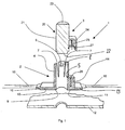
Eine erfindungsgemäße Sensoranordnung 1 einer Einparkhilfe (PDC = Park Distance Control) an Fahrzeugteilen (Fig. 1) umfasst einen PDC-Halter 2 und einen PDC-Sensor 3. Der PDC-Halter 2 besitzt eine hohlzylindrische Aufnahmebuchse 4 zur Aufnahme des PDC-Sensors 3. Die hohlzylindrische Buchse 4 besitzt eine Zylindermantelwandung 5. In der Zylindermantelwandung 5 sind erste Rastmittel 6 vorhanden. Beidseitig der Rastmittel 6 ist die Zylindermantelwandung 5 mit Federschlitzen 7 ausgebildet, welche sich axial von einer Stirnseite 8 der Mantelwandung 5 in die Buchse 4 hinein erstrecken. Durch diese Rastmittel kann die Montage und Demontage des Sensors 3 in einfacher und schneller Weise erfolgen, wobei gleichzeitig eine sichere Festlegung des Sensors 3 im Halter 2 gewährleistet ist. Im Bereich einer gegenüberliegenden Stirnwandung 9 besitzt der PDC-Halter 2 einen Befestigungsflansch 10, der sich radial von der Stirnfläche 9 nach außen erstreckt. Der Befestigungsflansch 10 kann quadratisch, rechteckig oder sich von der Buchse 4 radial nach außen erstreckend kreisrund ausgebildet sein. Der Befestigungsflansch 10 besitzt eine Auflagefläche 11, mit der er auf einer Stoßfängerverkleidung oder einer Stoßleiste 12 aufsitzt. Die Befestigung des Halters 2 kann auf vielfältige Weise erfolgen, z. B. durch Verklebung, Ultraschallschweißen, Laserschweißen, Reibschweißen oder durch eine formschlüssige (Klips-)Verbindung.A
Auf einer gegenüberliegenden Fläche besitzt der Befestigungsflansch 10 eine Steckverbindereinrichtung 14, welche beispielsweise kastenartig ausgebildet ist und sich von dem Befestigungsflansch 10 bzw. seiner Fläche 13 entlang der Zylindermantelwandung 5 weg erstreckt. Von einer Stirnseite 15 des Befestigungsflansches 10 zu einer gegenüberliegenden Stirnseite 15 des Befestigungsflansches 10 durchquert eine elektrische Leitung 16 den Befestigungsflansch 10, wobei geeignete Mittel vorhanden sind, welche entsprechende Leiterbahnen (nicht gezeigt) mit der Steckverbindereinrichtung 14 kontaktieren. Die elektrische Leitung 16 und der Halter 2 sind durch geeignete Maßnahmen einstückig und entsprechend der Vorgabe elektrisch leitend verbunden. Geeignete Maßnahmen sind z. B. das Einspritzen, Vergießen oder Aufsetzen und Verrasten eines Deckels jeweils nach der Herstellung der Kontaktierung.On an opposite surface of the mounting
Der PDC-Sensor 3 besitzt ein zylindrisches Gehäuse 20 mit einer Zylindermantelwandung 21 und einer Stirnfläche 22 sowie einer gegenüberliegenden Stirnfläche 23. Die Stirnfläche 22 ist eine Sensorfläche 22, welche in montiertem Zustand zur Fahrzeugaußenseite zur Aufnahme von Signalen gerichtet ist. Die Farbgebung der Sensorfläche 22 entsprechend der Farbe der Stoßfängerverkleidung 12 oder einer Stoßleiste 12 kann durch spezielle Drucktechniken (z. B. Tampoprint, Offsetdruck, Siebdruck) oder Aufbringen einer Farbfolie erfolgen. Hierdurch wird im Vergleich zu einem Lackierverfahren eine Vereinfachung und eine Verringerung des Ausschusses durch fehlerhafte Lackierung (Lackdicke, Lacknasen) erreicht.The
Die Stirnfläche 23 ist glattflächig ausgeführt und bietet dadurch eine geeignete Ansatzfläche für das manuelle Einsetzen (beispielsweise mit dem Daumen) des Sensors 3. Außerdem ist es vorteilhaft, die Länge der Buchse 4 und des Sensors 3 so aufeinander abzustimmen, dass bei in den Halter 2 eingesetztem Sensor 3 die Stirnfläche 23 und die Stirnseite 8 der Mantelwandung 5 der Buchse 4 miteinander fluchten. Hierdurch ist eine optische und haptische Rückmeldung über die vollständige Verrastung des Sensors 3 im Halter 2 gegeben.The
An der Zylindermantelwandung 21 ist eine Steckverbindereinrichtung 24 angeordnet, welche zu der Steckverbindereinrichtung 14 des PDC-Halters 2 korrespondierend ausgebildet ist. Somit kann die Steckverbindereinrichtung 14 des Halters 2 männlich und die Steckverbindereinrichtung 24 des PDC-Sensors 3 weiblich oder umgekehrt ausgebildet sein. Die aufnehmende Steckverbindereinrichtung, in diesem Fall die Steckverbindereinrichtung 24, besitzt vorstehende Steckkontakte 25, welche in entsprechende Aufnahmen 26 der Steckverbindereinrichtung 14 einsteckbar sind. Zudem ist eine umlaufende Dichtung 27 vorhanden, welche in montiertem Zustand die aufgenommene Steckverbindereinrichtung 24 derart umschließt, dass das Eindringen von Feuchtigkeit verhindert wird.On the Zylindermantelwandung 21 a
Zudem sind an dem Sensor 3 korrespondierend zu den Rastmitteln 6 zweite Rastmittel (nicht gezeigt) vorgesehen. Sind die Rastmittel 6 am PDC-Halter- wie in Fig. 1 dargestellt - Rastöffnungen, sind an entsprechender korrespondierender Stelle am Sensor 3 entsprechende Rastvorsprünge angeordnet oder umgekehrt.In addition, 6 second locking means (not shown) are provided on the
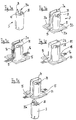
Bei einer weiteren Ausführungsform der Erfindung (Fig. 2) umfasst die Anordnung 1 einen Halter 2 und einen PDC-Sensor 3. Der Halter 2 ist hohlzylindrisch einseitig geschlossen mit einer Zylindermantelwandung 30 und einer Stirnwandung 31 ausgebildet. Gegenüberliegend der Stirnwandung ist an einer Stirnfläche des Halters 2 radial nach außen vorstehend ein Befestigungsflansch 33 angeordnet. Der Befestigungsflansch 33 und die Zylindermantelwandung 30 sind einstückig ausgebildet. Im Bereich der Stirnwandung 31 ist innenseitig des hohlzylindrischen Halters 2 eine Steckverbindereinrichtung 34 angeordnet. Die Steckverbindereinrichtung 34 kann männlich oder weiblich ausgebildet sein. Der Halter 2 wird im Bereich der Stirnwandung 31 von einer Seite der Zylindermantelwandung 30 zu einer diametral gegenüberliegenden Seite der Zylindermantelwandung 30 von einer elektrischen Leitung 16 durchquert, wobei geeignete Mittel vorhanden sind, welche entsprechende Leiterbahnen (nicht gezeigt) mit der Steckverbindereinrichtung 34 kontaktieren. Die elektrische Leitung 16 und der Halter 2 sind durch geeignete Maßnahmen einstückig und entsprechend der Vorgabe elektrisch leitend verbunden. Geeignete Maßnahmen sind z. B. das Einspritzen, Vergießen oder Aufsetzen und Verrasten eines stirnseitigen Deckels jeweils nach der Herstellung der Kontaktierung.In a further embodiment of the invention (FIG. 2), the
Die Anbindung der elektrischen Leitung 16 (Leiterbahn, Stanzgitter etc.) an den Halter 2 erfolgt beispielsweise im Mehr-Komponenten-Spritzgussverfahren, um bereichsweise unterschiedliche Elastizitäten im Halter 2 zu erzielen. Hierzu wird im Bereich der elektrischen Anschlüsse eine vergleichsweise weiche Komponente eingesetzt (zum Beispiel TPE), um eine sichere Abdichtung des elektrischen Kontaktbereichs zu erreichen. Die zweite Komponente ist beispielsweise ein Standardthermoplast, der eine ausreichende Festigkeit sowie die erforderlich "harte" Oberfläche des Halters 2 erzeugt.The connection of the electrical line 16 (conductor track, stamped grid, etc.) to the
Mit dem Befestigungsflansch 33 ist der hohlzylindrische PDC-Halter 2 im Bereich einer kreisringförmigen Ausnehmung 37 in einer Stoßfängerverkleidung/Stoßleiste 12 angeordnet, wobei der Durchmesser der Öffnung 37 und der innere Durchmesser des hohlzylindrischen Halters 2 im Wesentlichen übereinstimmen und die Öffnung 37 und der Hohlzylinder axial fluchtend miteinander ausgerichtet sind. Innenseitig an der Zylindermantelwandung 30 ist eine Verdrehsicherungseinrichtung 38 in Form eines Vorsprungs 38 vorhanden. In der Zylindermantelwandung 30 ist zudem ein Rastmittel 39 in Form einer Rastausnehmung 39 vorhanden.With the mounting
Der PDC-Sensor 3 besitzt ein länglich zylindrisches Gehäuse bzw. ist länglich zylindrisch ausgebildet mit einer Zylindermantelwandung 40, einer außenseitigen Sensorstirnseite 41 und einer Sensor-innenseitigen Stirnseite bzw. Wandung 42.The
Im Bereich der Mantelwandung 40 besitzt der PDC-Sensor 3 eine Verdrehsicherungseinrichtung 43, insbesondere eine zu dem Vorsprung 38 korrespondierende Verdrehsicherungsnut 43. Der Durchmesser des Sensors 3 ist vorzugsweise so bemessen, dass er dem Innendurchmesser des Halters 2 und der Öffnung 37 entspricht oder geringfügig kleiner ist. Die axiale Länge des Sensors 3 ist so bemessen, dass er zwischen den Stirnflächen 41, 42 einer einsteckbaren Länge in den Halter 2 entspricht, wobei eine Außenfläche 41 des Sensors 3 vorzugsweise mit einer Außenfläche der Stoßfängerverkleidung 12 bzw. Stoßleiste 12 abschließt oder geringfügig zurücksteht. Im Bereich der Mantelwandung 40 ist zudem eine Rasteinrichtung 44 vorhanden. Die Rasteinrichtung 44 ist beispielsweise eine Rastnase 44, welche in die Rastausnehmung 39 des Halters eingreift. Im Bereich der Stirnseiten 42 besitzt der Sensor 3 eine Steckverbindereinrichtung 45, welche mit der Steckverbindereinrichtung 34 korrespondiert. Die Steckverbindereinrichtung 45 ist somit entsprechend weiblich oder männlich ausgebildet. Im dargestellten Ausführungsbeispiel sind an der Steckverbindereinrichtung 34 vorstehende Steckkontakte 35 vorgesehen, welche in entsprechende Aufnahmen 36 der Steckverbindereinrichtung 45 einsteckbar sind.In the area of the
Während beim Ausführungsbeispiel nach Fig. 1 der Sensor von der Rückseite des Halters 3 in diesen eingesetzt wird, erfolgt bei den Ausführungsbeispielen nach den Fig. 2 und 3a bis 3e das Einsetzen des Sensors 3 in entgegengesetzter Richtung, indem der Sensor 2 von der Vorderseite des Halters 2 (der Stoßfängerverkleidung oder der Stoßleiste zugewandt) in diesen eingesetzt wird.While in the embodiment of FIG. 1, the sensor is inserted from the back of the
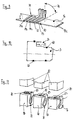
Um den Flach- oder Folienleiter 16 nicht beabstandet zu Stoßfängerverkleidungen bzw. Stoßleisten führen zu müssen, ist es bei der Ausführungsform gemäß den Fig. 3a bis 3e vorteilhaft, den Flach- oder Folienleiter 16 im Bereich des Flansches 33 am Halter anzuordnen. Hierbei trifft der Flach- oder Folienleiter 16 im Bereich einer ersten Kante 15 des Flansches 33 auf den Flansch 33 und wird von hier über den zylindrischen Teil des Halters 2 geführt, wobei im Bereich der Stirnwandung 31 die Kontaktierung erfolgt und an der gegenüberliegenden Fläche zu einer der ersten Kante 15 des Flansches diametral gegenüberliegenden Kante 15 des Flansches 10 geführt. Der Flach- oder Folienleiter 16 kann hierbei auf seinem gesamten Weg entlang des Halters 2 mit diesem in bereits beschriebener Weise einstückig ausgebildet, dass heißt vergossen oder eingespritzt sein. Durch diese Anordnung ist es in einfacher Weise möglich, den Flach- oder Folienleiter 16 entlang der Stoßfängerverkleidungsinnenseite zu führen.In order to avoid having to guide the flat or
Die Fig. 3a und 3b zeigen den Sensor 3 bzw. den Halter 2, vor dem Zusammensetzen. Wie aus Fig. 3c hervorgeht, wird in einem ersten Herstellschritt die Leiterbahn 16 in einer kanalartigen Aufnahme 2a an der Außenseite des Halters 2 entlanggeführt und anschließend gemäß Fig. 3d mit einem Hotmelt 2b vergossen. Im letzten Herstellschritt gemäß Fig. 3e wird nun der Sensor 3 in den zylindrischen Innenraum des Halters 2 eingeführt. Rastnasen 28 an der Stirnfläche 42 des Sensors 3 rasten hierbei in entsprechende Rastöffnungen 29 an der Stirnwandung 31 des Halters 2 ein (siehe auch Fig. 3c und 3d, mit in den Öffnungen 29 verrasteten Rastnasen 28). Mit dem Verrasten erfolgt gleichzeitig die Kontaktierung in dem nur schematisch dargestellten Kontaktbereich 35a. Der Halter 2 wird anschließend über den Flansch 33, an dem sich Rastvorsprünge 33a befinden, mir der Stoßfängerverkleidung oder der Stoßleiste verklipst.FIGS. 3a and 3b show the
Die erfindungsgemäße Anordnung sieht vor, dass eine elektrische Leitung 16, vorzugsweise ein Flach- oder Folienleiter 16, mit einer Mehrzahl von Leiterbahnen 17a bis 17c (Fig. 4 - 6), die Halter 2 nacheinander, entsprechend ihrer Abfolge in einer Stoßfängerverkleidung bzw. Stoßleiste durchgreift. Wie bereits ausgeführt sind die elektrische Leitung 16 und jeder Halter 2 durch geeignete Maßnahmen einstückig und entsprechend der Vorgabe elektrisch leitend verbunden. Geeignete Maßnahmen sind z. B. das Einspritzen, Vergießen oder Aufsetzen und Verrasten eines stirnseitigen Deckels jeweils nach der Herstellung der KontaktierungThe arrangement according to the invention provides that an
Eine elektrische Leitung 16 umfasst mehrere Leiterbahnen 17a bis 17c (Fig. 4-7). Hierbei sind eine Zuleitung 17a und eine Ableitung 17b vorhanden. Ferner umfasst die elektrische Leitung eine Mehrzahl von Signalleitungen 17c, wobei die Zahl der Signalleitungen 17c der Zahl der Sensoren 3 entspricht und jedem Sensor 3 eine Signalleitung 17c zugeordnet ist.An
Bei einer Ausführungsform der Erfindung nach Fig. 1 (Fig. 4) kann die elektrische Leitung 16 den Halter 2 im Bereich der Steckverbindereinrichtung 14 durchgreifen, entlang einer Seite des Halters 2, wobei mittels geeigneter Kontaktierungsmittel, z. B. Schneid-Klemmkontakten oder Gabelkontakten, die jeweils notwendigen bzw. gewünschten Leiterbahnen 17a, 17b, und 17c kontaktiert werden.In one embodiment of the invention according to FIG. 1 (FIG. 4), the
Bei einer Ausführungsform nach den Fig. 2, 3 und 5 durchgreift die elektrische Leitung 16 den Halter 2 mittig im Bereich der Stirnfläche 31, wobei dort ebenfalls mittels geeigneter Kontaktierungsmittel, z. B. Schneid-Klemmkontakten oder Gabelkontakten, die jeweilig notwendigen Leiterbahnen 17a, 17b, und 17c kontaktiert werden.In an embodiment according to FIGS. 2, 3 and 5, the
Bei Folienleitern kann die Kontaktierung über Durchstoßkontakte, Gabelkontakte oder Crimpkontakte erfolgen.For foil conductors, the contacting can be carried out via puncture contacts, fork contacts or crimp contacts.
Die Ausführungsformen nach Fig. 4 und Fig. 5 werden insbesondere dann verwendet, wenn Flachleiter 16 in Form von Meterware verwendet werden. Bei diesen Ausführungsformen ist es bei Verwendung von Flachleitern 16 erforderlich, die Halter 2 entsprechend ihrer Abfolge an der Stoßfängerverkleidung bzw. Stoßleiste mit unterschiedlich positionierten Kontaktierungsmitteln für die Leiterbahnen 17c auszustatten, da jeweils eine andere Leiterbahn 17c kontaktiert werden muss. Hierfür sind auch sogenannte Gabelkontakte 17 d (Fig. 7) geeignet, bei denen die Kontaktierung der Steckverbinderkontakte in immer gleicher Weise erfolgt, jedoch im Bereich des Abgriffs an den Leiterbahnen 17c, entsprechend der Stanzgittertechnik, nicht benötigte Kontaktierungspfade 17e entfernt werden. Unter Stanzgitter ist in Zusammenhang mit der vorliegenden Erfindung ein Gabelkontakt zu verstehen, der im Stanzverfahren aus einem Blech hergestellt wird.The embodiments according to FIGS. 4 and 5 are used in particular when
Bei einer weiteren Ausführungsform nach Fig. 1 (Fig. 6) durchgreift ein Folienleiter 16 den Halter 2 im Bereich des Befestigungsflansches 10, wobei hierbei die Konta k-tierungsmittel im Bereich des Flansches 10 verteilt angeordnet sind und geeignet zu der Steckverbindereinrichtung geführt werden. Bei diesen Ausführungsformen kann der Halter 2 hierfür über ein dreidimensionales Leitungsgitter beispielsweise in Stanzgittertechnik verfügen, welches direkt im Herstellungsprozess des PDC-Halters eingebracht wird. Auch bei dieser Ausführungsform können Gabelkontakte 17d in gleicher Weise wie zuvor beschrieben verwendet werden. Ferner ist es möglich, Leiterbahnen durch Beschichtungsverfahren aufzubringen. Hierdurch kann die Zahl der Montageschritte erheblich reduziert werden. Hierdurch wird ebenfalls für jede Position an der Stoßfängerverkleidung/Stoßleiste 12 ein vorkonfektionierter Halter 2 verwendet.In a further embodiment according to Fig. 1 (Fig. 6) passes through a
Bei der Verwendung von Folienleitern 16 ist es möglich, im dem Bereich, in dem der Folienleiter 16 die Kontakte des jeweiligen Halters 2 kontaktieren soll, ein Stanzgitter (nicht gezeigt) vorzusehen, bei dem die Leiterbahnen 17 von einer gleichen Anzahl von zueinander beabstandeten Leiterbahnen die hierzu in einem Winkel von 90° quer verlaufen kontaktiert werden, so dass jede Leiterbahn 17c eine der querverlaufenden Leiterbahnen in einem Kreuzungspunkt kontaktiert. Durch die Stanzgittertechnik ist es möglich, im Bereich der Kontaktstelle durch Herausstanzen entsprechender Gitterteile, die unterschiedlichen Signalleitungen 17c immer an einer Kontaktstelle vorzusehen bzw. hierher zu verlegen. Hierbei ist von Vorteil, dass einheitliche Halter mit einheitlich angeordneten Kontakten hergestellt werden können und lediglich der Folienleiter auf die Anzahl der vorhandenen Halter 2 vorkonfektioniert werden muss. Da die Halter 2 aufeinanderfolgend angeordnet sind, stellt diese Konfektionierung keinerlei Problem dar, da lediglich dafür gesorgt werden muss, dass die Leiterbahnen 17c nacheinander von Kontaktbereich (Stanzgitter) zum nachfolgenden Kontaktbereich (Stanzgitter) durch entsprechendes Stanzen auf den jeweiligen Kontaktpunkt gelegt werden müssen.When using
Bei einer weiteren Ausführungsform (Fig. 8) wird der Sensor 3 von der Außenseite der Stoßfängerverkleidung oder Stoßleiste 12 in den Halter 3 eingesetzt. Der PDC-Sensor 3 weist an seiner äußeren Stirnfläche 41 einen umlaufenden Ringflansch 50 auf, welcher in eine entsprechende Ringnut 51 der Stoßfängerverkleidung/Stoßleiste 12 eingepasst ist, wobei vorzugsweise die Fläche 41 mit der Au-ßenfläche der Stoßfängerverkleidung bündig abschließt. Um ein einheitliches Fugenbild zu gewährleisten, ist bei dieser Ausführungsform eine an dem Flansch 50 umlaufende Abstimmrippe 52 vorgesehen, welche den Fugenabstand exakt einstellt und die Fuge verschließt. Zudem kann eine Abstimmrippe 53 vorgesehen sein, welche am Nutboden 54 der Ringnut vorgesehen ist. Diese Rippe 53 kann insbesondere aus Kunststoff oder in Form einer Gummidichtung ausgeführt sein.In a further embodiment (FIG. 8), the
In Fig. 9 sind elektrische Kontaktzungen 71, 72 und 73 zur Bildung eines Stanzgitters 70 dargestellt, die über die Stanztechnik mit den einzelnen Leitern 17c eines Flachleiters 16 verbunden werden können. Hierbei gabelt sich die Kontaktzunge 71 in drei Einzelzungen 71a, 71b und 71c auf. Das Stanzgitter 70 kann als einheitliches Bauteil ausgeführt werden, wobei durch Biegen gemäß dem Pfeil 74 verschiedene Varianten gebildet werden können, die unter unterschiedlichen Winkeln zum Flachleiter 16 verlaufen.FIG. 9 shows
Während in Fig. 1 eine umlaufende Dichtung 27 innerhalb des Gehäuses der Steckverbindereinrichtung 24 dargestellt ist, sind gemäß Fig. 10 an der Außenseite des Sensors 3 (oder gleichwirkend an der inneren Mantelfläche 5 des Halters 2) radiale Dichtringe 60 vorgesehen, die den Bereich der Steckverbindereinrichtung 24 sowie den Aufnahmebereich des Sensors 3 gegen das Eindringen von Partikeln und Feuchtigkeit abdichten. Durch diese Ausgestaltung erübrigen sich aufwändige Abdichtungsmaßnahmen, insbesondere gegen das Eindringen von Wasser in den Bereich der Steckverbindereinrichtung 24.While in Fig. 1, a
Die Herstellung der Halter 2 kann beispielsweise gemäß Fig. 11 erfolgen, indem in einem einzigen Zyklus alle Halter 2 gebildet werden. Hierzu wird die Leiterbahn 16 in ein nicht näher dargestellten Werkzeug mit mehreren Kavitäten 80 eingelegt, wobei die Leiterbahn 16 zwischen den Kavitäten 80 "durchhängen" kann (Abschnitte 81). Nach dem Schließen des Werkzeuges durch die Oberteile 82 werden diejenigen Abschnitte 83 der Leiterbahn 16, die mit den Haltern 2 in elektrischen Kontakt gebracht werden, zusammen mit den eingebrachten Stanzgittern 70 umspritzt. Durch die gleichzeitige Herstellung mehrerer Halter 2 kann die Zykluszeit deutlich gesenkt werden.The preparation of the
Die als Flachleiter 16 ausgebildete Leiterbahn kann gemäß den Fig. 12 und 13 an der Innenseite der Stoßfängerverkleidung 12 befestigt werden. Wie Fig. 12 zeigt, ist an einer innenseitigen Einlage 90 der Stoßfängerverkleidung 12 eine Halterung 91 für den Flachleiter 16 vorgesehen, die aus einer Mehrzahl gegeneinander versetzter Laschen 92 mit abwechselnd entgegengesetzt gerichteten Vorsprüngen 93 besteht. Fig. 13 zeigt eine andere Ausführungsform einer Halterung 95, die aus einer an der Einlage 90 der Stoßfängerverkleidung 12 befestigten Aufnahme 96 sowie einem über ein Filmscharnier 97 angelenkten Deckel 98 besteht, dessen Nase 99 in einer Aussparung 94 verrasten kann. Der Flachleiter 16 kann in besonders einfacher Weise zwischen Aufnahme 96 und Deckel 98 geklemmt werden.Trained as a
Wie aus Fig. 14 hervorgeht, kann der Flachleiter 16 so vorbereitet sein, dass er gezielt gefaltet werden kann, um den Flachleiter 16 flexibel verlegen zu können, beispielsweise entlang von Rundungen oder um unterschiedliche Abstände zwischen den Haltern 2 auszugleichen. Denkbar ist hier beispielsweise die Anpassung an unterschiedliche Höhenlagen der einzelnen Sensoren 3. Des weiteren kann durch die Auch kann durch die Faltung an den Faltstellen 76 eine Zugentlastung eines Steckers 78 in Richtung des Pfeils 77 erreicht werden. Der Stecker 78 ist an einem freien Endabschnitt der Leitung 16 angeordnet, auf der bevorzugt eine Mehrzahl von Haltern 2 für die Sensoren 3 "aufgereiht" ist.As can be seen from FIG. 14, the
Fig. 15 zeigt eine hintere Stoßfängerverkleidung 12 mit einer versteifenden Stoßfängereinlage 61 im seitlich herumgezogenen Bereich 62. Wie oben beschrieben, ist eine Mehrzahl von Haltern 2 an der Stoßfängerverkleidung 12 angebracht. Der Flachleiter 16, der die einzelnen Halter 2 miteinander verbindet, endet in einem Stecker 78, der nach der Montage der Stoßfängerverkleidung 12 an das Fahrzeug mit dem Kabelbaum des Fahrzeugs verbunden wird. Zur Vermeidung von Verschmutzungen und Beschädigungen des freien Endabschnittes 63 des Flachleiters 16 und des Steckers 78 während des Transports und der Montage der Stoßfängerverkleidung 12 ist eine Aufnahme 64 an der Stoßfängereinlage 61 vorgesehen, die den Stecker 78 aufnimmt.15 shows a
Bei der Erfindung ist von Vorteil, dass sich PDC-Sensoren bei der Montage sehr leicht und schnell montieren lassen, wobei durch das Vorsehen von separaten Ve r-drehsicherungen oder der lagerspezifischen Vorsehung von Steckverbindereinrichtungen als Verdrehsicherung oder der räumlichen Ausbildung der Steckverbindereinrichtung derart als Verdrehsicherung dient, eine Fehlsteckung ausgeschlossen werden kann. Durch die Verwendung von Flachleitern als Meterware ist die Anordnung zudem preisgünstig zu realisieren, wobei beim Vorsehen von Flachleitern und die hierdurch mögliche Verwendung immer der geometrisch gleichen Kontaktierungspunkte keine Variantenerzeugung in den Haltern notwendig ist. Hierdurch werden in erheblichem Maß Zeit und Kosten gespart.In the invention, it is advantageous that PDC sensors can be mounted very easily and quickly during assembly, with the provision of separate locking locks or the bearing-specific provision of connector devices for preventing rotation or the spatial design of the connector device in such a way as preventing rotation , a miscarriage can be ruled out. By the use of flat conductors by the meter, the arrangement is also inexpensive to implement, with the provision of flat conductors and the possible use of this always the geometrically same contact points no variant generation in the holders is necessary. This saves considerable time and money.
Da die Folien- oder Flachleiter vorkonfektioniert sind, müssen keine getrennten Anschlussschritte mehr durchgeführt werden.Since the foil or flat conductors are prefabricated, it is no longer necessary to carry out separate connection steps.
Durch die Erfindung können einheitliche Sensoren für alle Fahrzeugbaureihen eines Herstellers eingesetzt werden. Darüber hinaus kann auch Hersteller übergreifend eine Vereinheitlichung stattfinden. Durch die einheitlichen Schnittstellen zur Peripherie und den Entfall von Varianten ergeben sich Kosteneinsparungen.The invention makes it possible to use uniform sensors for all vehicle series of a manufacturer. In addition, manufacturers can also take a unification across the board. The uniform interfaces to the peripherals and the elimination of variants result in cost savings.
Die Erfindung betrifft eine Sensoranordnung einer Einparkhilfe, wobei ein Halter 2 und ein Sensor 3 vorhanden sind und der Halter 2 zur Aufnahme des Sensors 3 ausgebildet ist, wobei am Halter 2 und am Sensor 3 korrespondierende Rasteinrichtungen vorhanden sind zum verrasteten Festlegen des Sensors 3 im Halter 2 in einer Endmontageposition, wobei am Halter 2 und am Sensor 3 in zusammengebautem Zustand miteinander korrespondierende Steckverbindungseinrichtungen 14 und 24 bzw. 34 und 45 vorhanden sind, wobei der Halter 2 über eine Stromversorgung in Form der elektrischen Leitungen 16 verfügt, so dass im eingebauten Zustand des Sensors 3 über die versteckten Steckverbindereinrichtungen 14 und 24 bzw. 34 und 45 eine elektrische Stromversorgung des Sensors 3 gewährleistet ist.The invention relates to a sensor arrangement of a parking aid, wherein a
Claims (15)
- A sensor arrangement in a parking aid for a bumper covering or bumper bar of a vehicle, comprising a number of holders (2), each adapted to receive a sensor (3), wherein mating plug-in connector devices (14, 24; 34, 45) are provided on the holder (2) and sensor (3) for locking and securing the sensor (3) in the holder (2),
characterised in that
an electric lead (16) is provided on the holder (2), the holder (2) and the electric lead (16) are in one piece and firmly connected, and the electric lead (16) and the majority of the holders (2) are connected to one another in succession, corresponding to their sequence in the bumper covering or bumper bar. - An arrangement according to claim 1,
characterised in that
the holder (2) and the electric lead (16), at least in the region in which strip conductors (17a to 17c) belonging to the electric lead (16) make electric contact with the holder (2) or the plug-in connector device (14, 34) thereof, is injection-moulded or encapsulated with the holder (2) or firmly connected thereto by a fitted-on, locked and/or stuck cover. - An arrangement according to claim 1 or claim 2,
characterised in that
the plug-in connector arrangements (14, 24; 34, 45), which are concealed when the sensor (3) is installed, supply electric current to the sensor. - An arrangement according to any of the preceding claims,
characterised in that
the electric leads (16) are flat or foil conductors (16) which are electrically contacted with the plug-in connector arrangement (14, 34) of the holder (2). - An arrangement according to any of the preceding claims,
characterised in that
contacting is via insulation-displacement contacts or tuning-fork contacts (17d) in the case of flat conductors and via push-through contacts, tuning-fork contacts (17d) or crimp contacts in the case of foil conductors. - An arrangement according to one or more of the preceding claims,
characterised in that
first locking means (6, 39) are provided on the holder (2) and second locking means (44) on the sensor (3) and lock together and in cooperation secure the sensor (3) in the holder (2) when the sensor (3) has been fully inserted into the holder (3). - An arrangement according to one or more of the preceding claims,
characterised in that
anti-twist devices (38, 43; 14, 24; 34, 35) are provided on the holder (2) and sensor (3) respectively and co-operate when the sensor (3) is inserted into the holder (2) and/or is in the inserted state. - An arrangement according to one or more of the preceding claims,
characterised in that
the plug-in connector devices (14, 24; 34, 45) are the anti-twist means. - An arrangement according to one or more of the preceding claims,
characterised in that
the electric lead (16) extends through the holder (2) in the neighbourhood of a plug-in connector device (14) disposed on a socket (4) for receiving the sensor (3), wherein the required or desired strip conductors (17a, 17b and 17c) are contacted via suitable contacting means or the electric lead (16) extends through the holder (2) in the region of an end face (31) of the holder (2) where the required strip conductors (17a, 17b and 17c) are contacted by suitable contacting means, or the electric lead (16) extends through the holder (2) in the region of the fastening flange (10), to which end the contact means in the region of the flange (10) are distributed and suitably led to the plug-in connector device (14, 34). - An arrangement according to one or more of the preceding claims,
characterised in that
when flat conductors (16) are used, the holders (2) are equipped with variously positioned contacting means for the strip conductors (17c) corresponding to their sequence on the bumper coverings or bumper bars (12), since a different strip conductor (17c) must be contacted in each case, wherein contacting is via tuning-fork contacts (17d), in which case the plug-in connector contacts are always contacted in the same way and unnecessary contacting paths (17e) are removed in the region of the pick-off on the strip conductors (17c). - An arrangement according to one or more of the preceding claims,
characterised in that
in the case of foil conductors (16) a punched grid is provided in the region in which the foil conductor (16) is to contact the contacts of the respective holder (2), wherein the strip conductors (17a to 17c) are contacted by an equal number of spaced-apart strip conductors which to this end run transversely at an angle of 90°, so that each strip conductor (17c) contacts one of the transverse conductors at a point of intersection, wherein in the contact region the various signal lines (17c) are always connected to a contact by punching out appropriate parts of the grid. - An arrangement according to one or more of the preceding claims,
characterised in that
when the electric lead (16) is contacted in the region of an end face (31) of the holder (2), the flat or foil conductor (16), in the region of a first edge (15) of the flange (10), is led on the flange (10) and thence over the cylindrical part (30) of the holder (2), wherein contact is made in the region of the end wall (31) and thence over the cylindrical part (30) of the holder (2), and is led down to an edge (15) of the flange diametrically opposite the first edge (15) of the flange (10). - An arrangement according to claim 9,
characterised in that
the flat or foil conductor (16), over its entire path along the holder (2), is integrally formed therewith, especially by encapsulation or injection-moulding. - An arrangement according to one or more of the preceding claims,
characterised in that
on its outer end face (41) the sensor (3) has a peripheral annular flange (50) which fits into a corresponding annular groove (51) in the bumper covering or bumper bar (12), wherein an outer surface (41) of the sensor (3) preferably ends flush with the outer surface of the bumper covering (12). - An arrangement according to any of the preceding claims,
characterised in that
projecting plug-in contacts (25; 35) are provided on the plug-in connector device (14, 24; 34, 45) and are insertable into corresponding recesses (26; 36) in the plug-in connector device (14, 24; 34, 45).
Applications Claiming Priority (3)
| Application Number | Priority Date | Filing Date | Title |
|---|---|---|---|
| DE10314862 | 2003-04-02 | ||
| DE10314862A DE10314862A1 (en) | 2003-04-02 | 2003-04-02 | Parking aid sensor arrangement |
| PCT/EP2004/003484 WO2004088352A1 (en) | 2003-04-02 | 2004-04-01 | Sensor arrangement of a parking aid |
Publications (2)
| Publication Number | Publication Date |
|---|---|
| EP1608994A1 EP1608994A1 (en) | 2005-12-28 |
| EP1608994B1 true EP1608994B1 (en) | 2007-07-18 |
Family
ID=32980919
Family Applications (1)
| Application Number | Title | Priority Date | Filing Date |
|---|---|---|---|
| EP04724994A Expired - Lifetime EP1608994B1 (en) | 2003-04-02 | 2004-04-01 | Sensor arrangement of a parking aid |
Country Status (3)
| Country | Link |
|---|---|
| EP (1) | EP1608994B1 (en) |
| DE (2) | DE10314862A1 (en) |
| WO (1) | WO2004088352A1 (en) |
Cited By (1)
| Publication number | Priority date | Publication date | Assignee | Title |
|---|---|---|---|---|
| DE102010024205A1 (en) * | 2010-06-17 | 2011-12-22 | Valeo Schalter Und Sensoren Gmbh | Ultrasonic sensor and vehicle with such an ultrasonic sensor |
Families Citing this family (14)
| Publication number | Priority date | Publication date | Assignee | Title |
|---|---|---|---|---|
| FR2890921B1 (en) * | 2005-09-19 | 2007-12-14 | Peugeot Citroen Automobiles Sa | ACCELEROMETERS IMPLANTES. |
| DE102005047181A1 (en) * | 2005-09-30 | 2007-04-05 | Robert Bosch Gmbh | Device for attaching sensor for pedestrian-protection system, has auxiliary structure which can be connected to sensor is provided, it being possible for this auxiliary structure to be permanently connected to support structure |
| DE102006007710A1 (en) * | 2006-02-14 | 2007-08-23 | Valeo Schalter Und Sensoren Gmbh | Sensor holder, in particular for mounting distance sensors on vehicle parts |
| ITMO20060225A1 (en) * | 2006-07-11 | 2008-01-12 | Meta System Spa | DEVICE FOR DETECTING OBJECTS NEAR VEHICLES, PARTICULARLY FOR APPLICATIONS IN PARKING, ANTI-INTRUSION OR SIMILAR ASSISTANCE SYSTEMS. |
| DE102009048173A1 (en) | 2009-10-02 | 2010-05-20 | Daimler Ag | Sensor arrangement i.e. park sensor arrangement, for use at e.g. rear bumper of car, has sensor accommodated in holder element that is adjustable between usage position and non-usage position |
| CN104067139B (en) * | 2012-02-03 | 2016-05-11 | 三菱电机株式会社 | Mounting structure of ultrasonic sensor module |
| DE102013200364A1 (en) | 2012-12-07 | 2014-06-12 | Decoma (Germany) Gmbh | body part |
| JP2016013812A (en) * | 2014-07-03 | 2016-01-28 | 株式会社デンソー | Mounting parts for vehicle parts |
| US10370129B2 (en) | 2015-08-17 | 2019-08-06 | Dash Llc | Assemblies including plug devices, and related plug devices and methods |
| DE102016010455B4 (en) | 2016-08-27 | 2020-09-17 | Preh Gmbh | Sensor device for measuring the interior temperature of a motor vehicle with locking means |
| FR3057239B1 (en) * | 2016-10-07 | 2021-02-19 | Renault Sas | SUPPORT FOR FIXING A FUNCTIONAL BODY WITH A CARRIER STRUCTURE, FOR EXAMPLE A SHIELD OF A MOTOR VEHICLE |
| DE102018005317A1 (en) * | 2018-07-05 | 2020-01-09 | Psa Automobiles Sa | Automotive trim |
| DE102019213895A1 (en) * | 2019-09-11 | 2021-03-11 | Robert Bosch Gmbh | Sensor housing for an ultrasonic sensor |
| DE102021210271A1 (en) | 2021-09-16 | 2023-03-16 | Magna Exteriors Gmbh | Process for manufacturing plastic components |
Family Cites Families (7)
| Publication number | Priority date | Publication date | Assignee | Title |
|---|---|---|---|---|
| DE19719519A1 (en) * | 1997-05-09 | 1998-11-12 | Bosch Gmbh Robert | Arrangement with a module for installation in a bumper of a motor vehicle |
| EP1005692B2 (en) * | 1997-08-21 | 2006-12-27 | Valeo Schalter und Sensoren GmbH | Sleeve for receiving a sensor, connected to the bumper of an automobile |
| DE19819698A1 (en) * | 1998-05-02 | 1999-11-11 | Daimler Chrysler Ag | Fixing device for build-on component of vehicle such as bumper (fender) |
| DE19943293C2 (en) * | 1999-09-10 | 2002-02-14 | Porsche Ag | Holding device for an ultrasonic transducer on an outer part of a motor vehicle |
| DE20010478U1 (en) * | 2000-06-16 | 2000-10-19 | Magna Exterior Systems GmbH, 63179 Obertshausen | Fastener |
| JP4251790B2 (en) * | 2001-06-19 | 2009-04-08 | 三菱電機株式会社 | Ultrasonic obstacle detection device and assembly method thereof |
| DE20118265U1 (en) * | 2001-11-09 | 2002-01-31 | REHAU AG + Co., 95111 Rehau | Device for fastening parking sensors |
-
2003
- 2003-04-02 DE DE10314862A patent/DE10314862A1/en not_active Withdrawn
-
2004
- 2004-04-01 EP EP04724994A patent/EP1608994B1/en not_active Expired - Lifetime
- 2004-04-01 DE DE502004004368T patent/DE502004004368D1/en not_active Expired - Lifetime
- 2004-04-01 WO PCT/EP2004/003484 patent/WO2004088352A1/en not_active Ceased
Cited By (1)
| Publication number | Priority date | Publication date | Assignee | Title |
|---|---|---|---|---|
| DE102010024205A1 (en) * | 2010-06-17 | 2011-12-22 | Valeo Schalter Und Sensoren Gmbh | Ultrasonic sensor and vehicle with such an ultrasonic sensor |
Also Published As
| Publication number | Publication date |
|---|---|
| DE502004004368D1 (en) | 2007-08-30 |
| EP1608994A1 (en) | 2005-12-28 |
| WO2004088352A1 (en) | 2004-10-14 |
| DE10314862A1 (en) | 2004-10-14 |
Similar Documents
| Publication | Publication Date | Title |
|---|---|---|
| EP1608994B1 (en) | Sensor arrangement of a parking aid | |
| DE4139434C2 (en) | Construction of electrical wiring for electrical components in a vehicle dashboard and for connection to the electrical system of a motor vehicle | |
| EP2780200B1 (en) | Housing and construction kit for a control apparatus | |
| DE102008051545B4 (en) | Multi-contact electronic device and method of making the same | |
| EP3416248B1 (en) | Cable feedthrough | |
| EP0368115A2 (en) | Central electrical distribution device, particulary for vehicules | |
| DE102010064351A1 (en) | Plastic component for electrically connecting e.g. direct-current motor of rear windscreen wiper in motor vehicle, has electro-conductive plastic element and insulating plastic element formed by injection of plastic material | |
| WO2020007555A1 (en) | Plug connecting element for a motor vehicle and method for producing a plug connecting element of this type | |
| EP2515388B1 (en) | Electric heating device | |
| WO2000072425A2 (en) | Electric motor, especially an electric geared motor for vehicle aggregates | |
| DE102014205744B4 (en) | Control unit for a vehicle heater | |
| EP1750109A1 (en) | Torque sensor and method for its production | |
| EP2368000B1 (en) | Exterior door handle, particularly for vehicles, and method for the production thereof | |
| DE19816216C2 (en) | Electrical plug and plug connection | |
| EP3728772A1 (en) | Vehicle door handle | |
| EP2208646B1 (en) | Connection housing for installation in an automotive body | |
| DE19804607C2 (en) | Arrangement for the electrical connection of at least one sensor | |
| EP0913889B1 (en) | Coupling element for an electric cable | |
| DE10161102A1 (en) | Wire plug-in connector for transmitting electric power between a cable and a printed circuit board with strip conductors in a casing has a locked but detachable plug socket and a connector strip | |
| EP2026418B1 (en) | Housing muffler with embedded component with at least one electromechanical component | |
| DE102005042248B3 (en) | Method for forming molded part e.g., for motor vehicle, has electric contact element provided in pluggable connector with conductor element and flat conductor | |
| WO2008087091A1 (en) | Multi-part contacting component | |
| EP1280390A2 (en) | Electronic key for vehicle | |
| DE102009023905B4 (en) | Electrical contact connector and electrical component | |
| WO2008058807A1 (en) | Plug arrangement in an auxiliary drive for a vehicle |
Legal Events
| Date | Code | Title | Description |
|---|---|---|---|
| PUAI | Public reference made under article 153(3) epc to a published international application that has entered the european phase |
Free format text: ORIGINAL CODE: 0009012 |
|
| 17P | Request for examination filed |
Effective date: 20050913 |
|
| AK | Designated contracting states |
Kind code of ref document: A1 Designated state(s): AT BE BG CH CY CZ DE DK EE ES FI FR GB GR HU IE IT LI LU MC NL PL PT RO SE SI SK TR |
|
| AX | Request for extension of the european patent |
Extension state: AL HR LT LV MK |
|
| DAX | Request for extension of the european patent (deleted) | ||
| RBV | Designated contracting states (corrected) |
Designated state(s): DE FR GB IT |
|
| GRAP | Despatch of communication of intention to grant a patent |
Free format text: ORIGINAL CODE: EPIDOSNIGR1 |
|
| GRAS | Grant fee paid |
Free format text: ORIGINAL CODE: EPIDOSNIGR3 |
|
| GRAA | (expected) grant |
Free format text: ORIGINAL CODE: 0009210 |
|
| AK | Designated contracting states |
Kind code of ref document: B1 Designated state(s): DE FR GB IT |
|
| REG | Reference to a national code |
Ref country code: GB Ref legal event code: FG4D Free format text: NOT ENGLISH |
|
| GBT | Gb: translation of ep patent filed (gb section 77(6)(a)/1977) |
Effective date: 20070726 |
|
| REF | Corresponds to: |
Ref document number: 502004004368 Country of ref document: DE Date of ref document: 20070830 Kind code of ref document: P |
|
| ET | Fr: translation filed | ||
| PLBE | No opposition filed within time limit |
Free format text: ORIGINAL CODE: 0009261 |
|
| STAA | Information on the status of an ep patent application or granted ep patent |
Free format text: STATUS: NO OPPOSITION FILED WITHIN TIME LIMIT |
|
| 26N | No opposition filed |
Effective date: 20080421 |
|
| REG | Reference to a national code |
Ref country code: FR Ref legal event code: PLFP Year of fee payment: 12 |
|
| PGFP | Annual fee paid to national office [announced via postgrant information from national office to epo] |
Ref country code: DE Payment date: 20150411 Year of fee payment: 12 Ref country code: GB Payment date: 20150430 Year of fee payment: 12 |
|
| PGFP | Annual fee paid to national office [announced via postgrant information from national office to epo] |
Ref country code: IT Payment date: 20150428 Year of fee payment: 12 Ref country code: FR Payment date: 20150430 Year of fee payment: 12 |
|
| REG | Reference to a national code |
Ref country code: DE Ref legal event code: R119 Ref document number: 502004004368 Country of ref document: DE |
|
| GBPC | Gb: european patent ceased through non-payment of renewal fee |
Effective date: 20160401 |
|
| REG | Reference to a national code |
Ref country code: FR Ref legal event code: ST Effective date: 20161230 |
|
| PG25 | Lapsed in a contracting state [announced via postgrant information from national office to epo] |
Ref country code: FR Free format text: LAPSE BECAUSE OF NON-PAYMENT OF DUE FEES Effective date: 20160502 Ref country code: DE Free format text: LAPSE BECAUSE OF NON-PAYMENT OF DUE FEES Effective date: 20161101 Ref country code: GB Free format text: LAPSE BECAUSE OF NON-PAYMENT OF DUE FEES Effective date: 20160401 |
|
| PG25 | Lapsed in a contracting state [announced via postgrant information from national office to epo] |
Ref country code: IT Free format text: LAPSE BECAUSE OF NON-PAYMENT OF DUE FEES Effective date: 20160401 |