EP2208646B1 - Connection housing for installation in an automotive body - Google Patents
Connection housing for installation in an automotive body Download PDFInfo
- Publication number
- EP2208646B1 EP2208646B1 EP20100150717 EP10150717A EP2208646B1 EP 2208646 B1 EP2208646 B1 EP 2208646B1 EP 20100150717 EP20100150717 EP 20100150717 EP 10150717 A EP10150717 A EP 10150717A EP 2208646 B1 EP2208646 B1 EP 2208646B1
- Authority
- EP
- European Patent Office
- Prior art keywords
- plug
- housing
- connection housing
- connection
- energy chain
- Prior art date
- Legal status (The legal status is an assumption and is not a legal conclusion. Google has not performed a legal analysis and makes no representation as to the accuracy of the status listed.)
- Active
Links
Images


Classifications
-
- B—PERFORMING OPERATIONS; TRANSPORTING
- B60—VEHICLES IN GENERAL
- B60R—VEHICLES, VEHICLE FITTINGS, OR VEHICLE PARTS, NOT OTHERWISE PROVIDED FOR
- B60R16/00—Electric or fluid circuits specially adapted for vehicles and not otherwise provided for; Arrangement of elements of electric or fluid circuits specially adapted for vehicles and not otherwise provided for
- B60R16/02—Electric or fluid circuits specially adapted for vehicles and not otherwise provided for; Arrangement of elements of electric or fluid circuits specially adapted for vehicles and not otherwise provided for electric constitutive elements
- B60R16/0207—Wire harnesses
- B60R16/0215—Protecting, fastening and routing means therefor
-
- H—ELECTRICITY
- H01—ELECTRIC ELEMENTS
- H01R—ELECTRICALLY-CONDUCTIVE CONNECTIONS; STRUCTURAL ASSOCIATIONS OF A PLURALITY OF MUTUALLY-INSULATED ELECTRICAL CONNECTING ELEMENTS; COUPLING DEVICES; CURRENT COLLECTORS
- H01R13/00—Details of coupling devices of the kinds covered by groups H01R12/70 or H01R24/00 - H01R33/00
- H01R13/56—Means for preventing chafing or fracture of flexible leads at outlet from coupling part
-
- H—ELECTRICITY
- H01—ELECTRIC ELEMENTS
- H01R—ELECTRICALLY-CONDUCTIVE CONNECTIONS; STRUCTURAL ASSOCIATIONS OF A PLURALITY OF MUTUALLY-INSULATED ELECTRICAL CONNECTING ELEMENTS; COUPLING DEVICES; CURRENT COLLECTORS
- H01R2201/00—Connectors or connections adapted for particular applications
- H01R2201/26—Connectors or connections adapted for particular applications for vehicles
Definitions
- connection housing according to claim 1 and a vehicle body with connection housing according to claim 12.
- energy chains are used to produce an electrically conductive connection between the body and a movable vehicle door, for example a sliding door.
- the electrical cables are routed in the energy chain.
- the energy chain represents a support structure, which is fastened with both ends to the body or to the vehicle door.
- a junction box for connecting electrical lines in a vehicle door of a vehicle.
- the connector housing accommodates two connectors, each connector having electrical leads. When mating in the connector housing an electrically conductive connection between the lines of the two connectors is made.
- an electrical line connection which has an inserted plug-in coupling, wherein a coupling part has a protective sleeve and the other coupling part two coaxially standing connection sleeves, and a cable guide.
- the components are both electrically and fluidly via fluid seals and subsequent electrical contacts on their
- the object of the invention is to provide an improved connection housing for the connection of an energy chain with a vehicle body.
- connection housing is that a simple and safe electrical connection between the first electrical lines of the energy chain and second electrical lines of the body in the connection housing is produced. Thus, it is easily possible to connect the energy chain to the terminal housing and simultaneously produce an electrically conductive connection.
- first sealing means for carrying out the first lines are formed in the first plug-in element. In this way, a secure seal of the first lines is achieved.
- a second sealing element is provided between the first plug-in element and the connection housing. As a result, the plug connection between the first plug-in element and the connection housing is also sealed.
- a first opening in the connection housing for the first plug-in element and a second opening is provided, wherein the second opening is closed with a lid.
- the second opening is arranged within the body and can be used for example for mounting the second lines on the second plug-in element or for introducing the second plug-in element.
- a third opening is provided, which is provided for supplying the second electrical lines.
- the third opening is preferably arranged inside the body.
- a sliding element in particular a sliding bar, which is used to guide the energy chain, is provided on the first plug element.
- the first plug-in element can be used simultaneously as a sliding element for guiding the energy chain. This improves the management of the energy chain.
- the first plug-in element has two parts, which are preferably connected to one another via latching connections.
- the first part has a housing insert and the sliding element, wherein the second part comprises a connection element for the chain.
- the connection element can be manufactured separately from the first part of the plug-in element.
- the connection element can be produced simultaneously by the supplier of the energy chain. This ensures that the energy chain can be optimally connected to the first plug-in element.
- the vehicle body according to the invention provides a simple and secure connection of an energy chain with electrical lines to a vehicle.
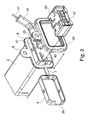
- FIG. 1 shows in a perspective view of the terminal housing 1 with a housing 2 and a first plug-in element 3.
- the housing 2 has an elongated cuboid shape substantially.
- the housing 2 has two oppositely arranged narrow side surfaces 18, 19, which are formed substantially rectangular. Furthermore, the housing has two parallel arranged upper and lower side surfaces 20, 21.
- a first and a second opening 4, 5 are provided at opposite ends of the cuboid shape.
- a first and a second opening 4, 5 are provided in the first opening 4, the first plug element 3 is inserted.
- the second opening 5 is covered with a removable cap 6.
- the cap 6 is connected via a retaining tab 7 with the housing 2.
- the cap 6, the tab 7 and the housing 2 is integrally formed.
- the housing 2, the cap 6 and the tab 7 may be made of plastic.
- the housing 2 has a circumferential bead 8 in a second end region, in which the second opening 5 is formed. At the bead 8, a fastening tab 9 is formed.
- the first plug-in element 3 has a connection element 10 for the energy chain. Via the connection element 10 first electrical leads 46 are supplied. Furthermore, the plug-in element 3 has a peripheral edge 11 which rests peripherally on one end face of the first opening 4. Furthermore, a sliding element in the form of a sliding bracket 12 is formed on the first plug-in element 3.
- the sliding bracket 12 has a sliding surface 55, which is guided across the entire width of the housing 2 and which is arranged substantially perpendicular to a plane of the upper and lower side surface 20, 21 of the housing 2. The slide bracket 12 is guided from the plane of the first narrow side surface 18 to the plane of the second narrow side surface 19.
- the distance of the uniform surface 55 increases from the edge 11 in the direction of the second end 62, which at the level of the second narrow side surface 19 ends.
- the housing 2 has in the region of the first opening 4 on the two narrow side surfaces 18, 19 of the housing 2 latching recesses 13, engage in the latching hooks 14 of the first plug-in element 3.
- a cable channel 15 for second electrical lines 47 is shown, which is guided laterally in the region of the second opening 5 to the housing 2.
- the cap 6 is cup-shaped, has a bottom surface and a peripheral edge with four substantially perpendicular thereto edge surfaces. In each edge surface, a second recess 16 is provided, are latched into the locking lugs 17 of the housing 2.
- housing 2 is surrounded by an annular third sealing element 60, with which the housing 2 is sealed against the body.
- FIG. 2 shows a mounted on an inner sill 22 of a motor vehicle housing 2, in which the first plug-in element 3 is inserted.
- a second plug-in element 23 is shown schematically, which is arranged adjacent to the second opening 5.
- a first sealing element 24 is arranged circumferentially on the bead 8.
- the first sealing element 24 covers at least one circumferential side surface of the bead 8, which faces the inner sill 22.
- the region of the housing 2, in which the second opening 5 is formed is disposed within the inner sill 22, ie in the interior 56 of the motor vehicle and thus protected against environmental influences, such as spray water.
- the inner sill 22 limits the sill to the interior of the vehicle.
- the second plug-in element 23 can be mounted in the housing 2 even after the connection housing 1 has been mounted from the inside 56 of the vehicle.
- the housing 2 is from the interior 56 into a recess 54 of the inner sill 22 inserted.
- the first sealing element 24 is pressed by the bead 8 against the inner skirts 22.
- the first plug-in element 3 For mounting the first plug-in element 3, the first plug-in element 3 is pushed from the outside of the body into the first opening 4 of the housing 2 until the first plug-in element 3 rests against the housing 11 with the edge 11 and the latching hooks 14 are engaged, and that first plug element 3 is inserted into the second plug-in element 23.
- Both the first plug-in element 3 and the second plug-in element 23 have electrical contacts, for example in the form of pins or sockets, which are contacted electrically when plugged together.
- the electrical contacts of the first and the second plug-in element 3, 23 are connected to the first and the second electrical lines 46, 47.
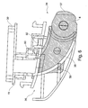
- FIG. 3 shows a representation of the housing 2, in which the second opening 5 is shown in the open state and the first sealing element 24 is shown as a circumferential ring seal prior to assembly.
- the first sealing element 24 has substantially the same contour as the bead 8.
- the first sealing element 24 is pushed onto the housing 2 via the second opening 5.
- the second plug-in element 23 is shown, which is inserted into the second opening 5 and locked with second latching noses 63 of the housing 2.
- a third opening 25 is shown, which is arranged in the second narrow side wall 19 of the housing 2 between the bead 8 and the second opening 5.
- the cable channel 15 is guided to the third opening 25 and covers the third opening 25.
- the cap 6 in a narrow side wall has a cutout 26 through which the cable channel 15 is guided in the closed position of the cap 6.
- the second plug-in element 23 has, for example, contact sockets 57 for inserting contact pins of the first plug-in element 3 and for plugging in contacts of the second lines.
- FIG. 3 the second electrical lines 47 are shown, which are guided via the cable channel 15 through the third opening 3 in the housing 2 and are connected in the assembled state with electrical contacts of the second plug-in element 23.
- FIG. 4 shows in an exploded view of individual parts of the first plug-in element 3.
- the first plug-in element 3 has a contact plug 27, the contact pins 28 has.
- the contact plug 27 has substantially the inner cross-section and the cuboid shape of the housing 2 with a shortened length, so that the contact plug 27 can be inserted into the housing 2 via the first opening 4.
- the first plug-in element 3 has a peripheral second sealing element 29.
- a housing insert 30 is provided in the first plug-in element 3, which can be inserted into the contact plug 27 and is releasably connected via further latching lugs 58 with further latching recesses 59 of the contact plug 27.
- the housing insert 30 has three side walls and a cover plate 31 arranged perpendicular thereto.
- a second conduit opening 49 is provided in the cover plate 31 .
- First electrical lines 46 are guided through a first conduit opening 48 of a head piece 34 and through the second conduit opening 49 of the housing insert 30 to the contact pins 28.
- a ring seal 33 is inserted in the first and second conduit opening 48, 49.
- the ring seal 33 seals the first and second conduit openings 48, 49 during the passage of the first lines 46.
- the head piece 34 is formed on the first plug-in element 3, which has the connecting element 10 for the energy chain and the sliding bar 12.
- the head piece 34 is in turn connected via second latching hook 35 with the housing insert 30.
- FIG. 5 The second sealing element 29 is clamped between the cover plate 31 and the contact plug 27 and spaced from the edge 11 and surrounds the contact plug 27 in a plane perpendicular to the insertion direction and longitudinal direction of the contact plug 27. In the assembled position, the seal 29 is also inserted correspondingly deep into the housing 2.
- the head piece 34 consists of a first partial head piece 36 and a second partial head piece 37.
- the second partial head piece 37 and the first partial head piece 36 are interconnected via snap-in connections 50, which are in the form of Rear hook, locking lugs and receiving ribs may be formed.
- the second partial head piece 37 is in FIG. 6 hatched and substantially comprises the connection element 4th
- FIG. 7 shows the first partial head piece 36 and the second partial head piece 37 before mating. It can be seen that on the underside of the second part of the head piece 37 a support boss 38 is formed. The support pad 38 is used for support on the body.
- the second partial head piece 37 consists essentially of two parallel side plates 42, 43, which are connected to one another via two transverse webs 44, 45. Between the side plates 42, 43, the first leads 46 of the energy chain are led to the contact plug 27.
- FIG. 8 shows a schematic representation of a part of a vehicle body 51 with the terminal housing 1 and the energy chain 39, which is attached to the first plug-in element 3 is.
- the energy chain 39 has individual chain links 40, wherein additionally a contact pin 41 is formed on at least one chain link 40 and faces the slide bar 12.
- the contact pin 41 is spaced from the chain link 40 by an arm 32.
- the arm 32 is directed towards the connection housing 1 and preferably integrally connected to the chain link 40.
- the contact pin 41 and / or a chain link 40 are guided along the slide bar 12.
- the sliding bar 12 on the sliding surface 55.
- the sliding bracket 12 is disposed in a recess of an outer sill 53 of the body.
- connection housing With the aid of the described connection housing, a mechanically simple, reliable and easy-to-handle electrical and mechanical attachment of an energy chain to the body 51 of a vehicle can be achieved.
- a sill 53 of the vehicle has a recess 54, into which the first plug-in element 3 can be inserted from the outside up to the inner sill 22.
- the housing 2 is inserted from the interior into the recess 54 of the inner sill 22, so that the second opening 5 of the connection housing 1 projects into the interior 55 of the vehicle.
- the housing 2 is surrounded by a third sealing element 60, for example, a sealing ring, which seals the housing 2 circumferentially against the inner sill 22.
- the sliding bracket 12 extends over the entire width of the recess 54 and is guided from the height of the edge 11 to an outer side of a first chain link 40 of the energy chain 39.
- a sliding surface 55 is provided, the obliquely inclined from the outside of the inner sill 22 to the outside of the first chain link 40 is guided.
- Fig. 8 shows a position in which a sliding door, not shown, to which a second unillustrated end of the energy chain 39 is connected, is in the closed state. If the sliding door is opened, ie in Fig. 8 moved to the right, then the energy chain 39 is shifted to the right, wherein the abutment pin 41 is moved in the direction of the arrow shown. In this case, the contact pin 41 comes into contact with the sliding surface 55 and slides along the sliding surface 55. As a result, the energy chain 39 is guided according to a desired guideway, which allows improved pivoting of the energy chain 39 when opening and closing the sliding door. Depending on the chosen embodiment, the contact pin 41 can be dispensed with and the energy chain 39 slides with the chain links on the sliding surface 55 of the sliding bar 12.
Description
Die Erfindung betrifft ein Anschlussgehäuse gemäß Patentanspruch 1 und eine Fahrzeugkarosserie mit Anschlussgehäuse gemäße Patentanspruch 12.The invention relates to a connection housing according to
In Kraftfahrzeugen werden Energieketten eingesetzt, um eine elektrisch leitende Verbindung zwischen der Karosserie und einer beweglichen Fahrzeugtür, beispielsweise einer Schiebetür herzustellen. Dabei sind die elektrischen Leitungen in der Energiekette geführt. Die Energiekette stellt eine Stützstruktur dar, die mit beiden Enden an der Karosserie bzw. an der Fahrzeugtür befestigt ist.In motor vehicles energy chains are used to produce an electrically conductive connection between the body and a movable vehicle door, for example a sliding door. The electrical cables are routed in the energy chain. The energy chain represents a support structure, which is fastened with both ends to the body or to the vehicle door.
Aus
Aus
Aus
Übergängen miteinander verbunden. An die elektrische Leitungsverbindung ist ein elektrisches Kabel angeschlossen.Transitions connected with each other. An electrical cable is connected to the electrical line connection.
Die Aufgabe der Erfindung besteht darin, ein verbessertes Anschlussgehäuse für die Verbindung einer Energiekette mit einer Fahrzeugkarosserie bereitzustellen.The object of the invention is to provide an improved connection housing for the connection of an energy chain with a vehicle body.
Die Aufgabe der Erfindung wird durch das Anschlussgehäuse gemäß Patentanspruch 1 und die Fahrzeugkarosserie gemäß Anspruch 12 gelöst.The object of the invention is achieved by the connection housing according to
Weitere vorteilhafte Ausführungsformen der Erfindung sind in den abhängigen Ansprüchen angegebenen.Further advantageous embodiments of the invention are specified in the dependent claims.
Ein Vorteil des erfindungsgemäßen Anschlussgehäuses besteht darin, dass eine einfache und sichere elektrische Verbindung zwischen ersten elektrischen Leitungen der Energiekette und zweiten elektrischen Leitungen der Karosserie im Anschlussgehäuse hergestellt wird. Somit ist es auf einfache Weise möglich, die Energiekette an das Anschlussgehäuse anzustecken und gleichzeitig eine elektrisch leitende Verbindung herzustellen.An advantage of the connection housing according to the invention is that a simple and safe electrical connection between the first electrical lines of the energy chain and second electrical lines of the body in the connection housing is produced. Thus, it is easily possible to connect the energy chain to the terminal housing and simultaneously produce an electrically conductive connection.
In einer weiteren Ausführungsform sind erste Dichtmittel zum Durchführen der ersten Leitungen im ersten Steckelement ausgebildet. Auf diese Weise wird eine sichere Abdichtung der ersten Leitungen erreicht.In a further embodiment, first sealing means for carrying out the first lines are formed in the first plug-in element. In this way, a secure seal of the first lines is achieved.
In einer weiteren Ausführungsform ist ein zweites Dichtelement zwischen dem ersten Steckelement und dem Anschlussgehäuse vorgesehen. Dadurch wird auch die Steckverbindung zwischen dem ersten Steckelement und dem Anschlussgehäuse abgedichtet.In a further embodiment, a second sealing element is provided between the first plug-in element and the connection housing. As a result, the plug connection between the first plug-in element and the connection housing is also sealed.
In einer weiteren Ausführungsform ist eine erste Öffnung im Anschlussgehäuse für das erste Steckelement und eine zweite Öffnung vorgesehen, wobei die zweite Öffnung mit einem Deckel verschlossen ist. Im montierten Zustand ist die zweite Öffnung innerhalb der Karosserie angeordnet und kann beispielsweise zur Montage der zweiten Leitungen am zweiten Steckelement oder zum Einbringen des zweiten Steckelementes verwendet werden. Somit ist eine einfache Montage der zweiten Leitungen und des zweiten Steckelements im Anschlussgehäuse möglich.In a further embodiment, a first opening in the connection housing for the first plug-in element and a second opening is provided, wherein the second opening is closed with a lid. In the assembled state, the second opening is arranged within the body and can be used for example for mounting the second lines on the second plug-in element or for introducing the second plug-in element. Thus, a simple assembly of the second lines and the second plug element in the connection housing is possible.
In einer weiteren Ausführungsform ist eine dritte Öffnung vorgesehen, die zum Zuführen der zweiten elektrischen Leitungen vorgesehen ist. Auf diese Weise ist eine einfache Zuführung der zweiten elektrischen Leitungen unabhängig von der zweiten Öffnung möglich. Die dritte Öffnung ist vorzugsweise innerhalb der Karosserie angeordnet.In a further embodiment, a third opening is provided, which is provided for supplying the second electrical lines. In this way, a simple supply of the second electrical lines is possible independently of the second opening. The third opening is preferably arranged inside the body.
In einer weiteren Ausführungsform ist am ersten Steckelement ein Gleitelement, insbesondere ein Gleitbügel vorgesehen, der zum Führen der Energiekette verwendet wird. Somit kann das erste Steckelement gleichzeitig als Gleitelement zur Führung der Energiekette verwendet werden. Damit wird die Führung der Energiekette verbessert.In a further embodiment, a sliding element, in particular a sliding bar, which is used to guide the energy chain, is provided on the first plug element. Thus, the first plug-in element can be used simultaneously as a sliding element for guiding the energy chain. This improves the management of the energy chain.
In einer weiteren Ausführungsform weist das erste Steckelement zwei Teile auf, die vorzugsweise über Rastverbindungen miteinander verbunden sind. Das erste Teil weist einen Gehäuseeinsatz und das Gleitelement auf, wobei das zweite Teil ein Anschlusselement für die Kette umfasst. Auf diese Weise ist es möglich, dass das Anschlusselement separat von dem ersten Teil des Steckelementes hergestellt werden kann. Damit kann das Anschlusselement gleichzeitig vom Lieferanten der Energiekette hergestellt werden. Somit ist sicher gestellt, dass die Energiekette optimal mit dem ersten Steckelement verbunden werden kann.In a further embodiment, the first plug-in element has two parts, which are preferably connected to one another via latching connections. The first part has a housing insert and the sliding element, wherein the second part comprises a connection element for the chain. In this way, it is possible that the connection element can be manufactured separately from the first part of the plug-in element. Thus, the connection element can be produced simultaneously by the supplier of the energy chain. This ensures that the energy chain can be optimally connected to the first plug-in element.
Durch die erfindungsgemäße Fahrzeugkarosserie wird eine einfache und sichere Anbindung einer Energiekette mit elektrischen Leitungen an eine Fahrzeug bereitgestellt.The vehicle body according to the invention provides a simple and secure connection of an energy chain with electrical lines to a vehicle.
Die Erfindung wird im Folgenden anhand der Figuren näher erläutert. Es zeigen
-
Fig. 1 eine perspektivische Darstellung einer Anschlussdose, -
Fig. 2 die Anschlussdose vor der Montage, -
Fig. 3 eine Rückansicht der Anschlussdose, -
Fig. 4 eine Explosionsdarstellung des ersten Steckelementes, -
Fig. 5 das erste Steckelement beim Einstecken in die Anschlussdose, -
Fig. 6 eine Teildarstellung des ersten Steckelementes, -
Fig. 7 zwei Einzelteile des ersten Steckelementes und -
Fig. 8 eine montierte Anschlussdose mit der Energiekette.
-
Fig. 1 a perspective view of a junction box, -
Fig. 2 the junction box before mounting, -
Fig. 3 a rear view of the junction box, -
Fig. 4 an exploded view of the first plug-in element, -
Fig. 5 the first plug-in element when plugged into the junction box, -
Fig. 6 a partial view of the first plug-in element, -
Fig. 7 two items of the first plug-in element and -
Fig. 8 a mounted junction box with the energy chain.
Das erste Steckelement 3 weist ein Anschlusselement 10 für die Energiekette auf. Über das Anschlusselement 10 werden erste elektrische Leitungen 46 zugeführt. Weiterhin weist das Steckelement 3 einen umlaufenden Rand 11 auf, der auf einer Stirnseite der ersten Öffnung 4 umlaufend aufliegt. Weiterhin ist ein Gleitelement in Form eines Gleitbügels 12 am ersten Steckelement 3 ausgebildet. Der Gleitbügel 12 weist eine Gleitfläche 55 auf, die quer über die gesamte Breite des Gehäuses 2 geführt ist und die im Wesentlichen senkrecht zu einer Ebene der oberen und unteren Seitenfläche 20, 21 des Gehäuses 2 angeordnet ist. Der Gleitbügel 12 ist ausgehend von der Ebene der ersten schmalen Seitenfläche 18 bis zur Ebene der zweiten Schmalen Seitenfläche 19 geführt. Ausgehend von einem ersten Abschnitt 61, der parallel zur ersten schmalen Seitenfläche 18 angeordnet ist, vergrößert sich der Abstand der Gleichfläche 55 von dem Rand 11 in Richtung auf das zweite Ende 62, das auf der Höhe der zweiten schmalen Seitenfläche 19 endet. Das Gehäuse 2 weist im Bereich der ersten Öffnung 4 an den zwei schmalen Seitenflächen 18, 19 des Gehäuses 2 Rastausnehmungen 13 auf, in die Rasthaken 14 des ersten Steckelements 3 eingreifen.The first plug-in
Weiterhin ist ein Kabelkanal 15 für zweite elektrische Leitungen 47 dargestellt, der seitlich im Bereich der zweiten Öffnung 5 zum Gehäuse 2 geführt ist. Die Kappe 6 ist topfförmig ausgebildet, weist eine Bodenfläche und einen umlaufenden Rand mit vier im Wesentlichen senkrecht dazu stehenden Randflächen auf. In jeder Randfläche ist eine zweite Rastausnehmung 16 vorgesehen, in die Rastnasen 17 des Gehäuses 2 eingerastet sind.Furthermore, a
Zudem ist das Gehäuse 2 von einem ringförmigen dritten Dichtelement 60 umgeben, mit dem das Gehäuse 2 gegen die Karosserie abgedichtet wird.In addition, the
Zur Montage des ersten Steckelementes 3 wird das erste Steckelement 3 von der Außenseite der Karosserie in die erste Öffnung 4 des Gehäuses 2 so tief eingeschoben, bis das erste Steckelement 3 mit dem Rand 11 am Gehäuse 2 anliegt und die Rasthaken 14 eingerastet sind, und das erste Steckerelement 3 in das zweite Steckelement 23 eingesteckt ist. Sowohl das erste Steckelement 3 als auch das zweite Steckelement 23 weisen elektrische Kontakte, beispielsweise in Form von Stiften oder Buchsen auf, die beim Zusammenstecken miteinander elektrisch kontaktiert werden. Die elektrischen Kontakte des ersten und des zweiten Steckelementes 3, 23 sind mit den ersten bzw. den zweiten elektrischen Leitungen 46, 47 verbunden.For mounting the first plug-in
Weiterhin ist eine dritte Öffnung 25 dargestellt, die in der zweiten schmalen Seitenwand 19 des Gehäuses 2 zwischen der Wulst 8 und der zweiten Öffnung 5 angeordnet ist. Zudem ist der Kabelkanal 15 an die dritte Öffnung 25 geführt und überdeckt die dritte Öffnung 25. Weiterhin weist die Kappe 6 in einer schmalen Seitenwand einen Ausschnitt 26 auf, durch den in der geschlossenen Position der Kappe 6 der Kabelkanal 15 geführt ist. Somit wird trotz der Ausbildung des Kabelkanals 15 eine sichere Abdeckung der zweiten Öffnung 5 durch die Kappe 6 ermöglicht.Furthermore, a
Das zweite Steckelement 23 weist beispielsweise Kontaktbuchsen 57 zum Einstecken von Kontaktstiften des ersten Steckelementes 3 und zum Einstecken von Kontakten der zweiten Leitungen auf.The second plug-in
Weiterhin sind in
Das zweite Teilkopfstück 37 besteht im Wesentlichen aus zwei parallel angeordneten Seitenplatten 42, 43, die über zwei Querstege 44, 45 miteinander verbunden sind. Zwischen den Seitenplatten 42, 43 sind die ersten Leitungen 46 der Energiekette zum Kontaktstecker 27 geführt.The second
Mit Hilfe des beschriebenen Anschlussgehäuses kann eine mechanisch einfache, zuverlässig und einfach handzuhabende elektrische und mechanische Befestigung einer Energiekette mit der Karosserie 51 eines Fahrzeugs erreicht werden. Zur Befestigung des Anschlussgehäuses 1 weist ein Schweller 53 des Fahrzeugs eine Ausnehmung 54 auf, in die das erste Steckelement 3 von außen bis zu dem Innenschweller 22 eingesteckt werden kann. Das Gehäuse 2 ist ausgehend von dem Innenraum in die Ausnehmung 54 des Innenschwellers 22 eingesteckt, sodass die zweite Öffnung 5 des Anschlussgehäuses 1 in den Innenraum 55 des Fahrzeugs ragt. Das Gehäuse 2 ist von einem dritten Dichtelement 60 beispielsweise einem Dichtring umgeben, das das Gehäuse 2 umlaufend gegen den Innenschweller 22 abdichtet. Damit ist der Freiraum zwischen dem Gehäuse 2 und dem Innenschweller 22 abgedichtet, so dass keine Feuchtigkeit über die Ausnehmung 54 in den Innenraum des Fahrzeuges eindringen kann. Die Wulst 8 liegt dabei an einer Innenseite des Innenschwellers 22. Auf diese Weise wird eine kompakte und sichere Anordnung des Anschlussgehäuses 1 ermöglicht. Der Gleitbügel 12 erstreckt sich über die gesamte Breite der Ausnehmung 54 und ist von der Höhe des Randes 11 bis auf eine Außenseite eines ersten Kettengliedes 40 der Energiekette 39 geführt. Damit wird eine Gleitfläche 55 bereitgestellt, die schräg geneigt von der Außenseite des Innenschwellers 22 bis zur Außenseite des ersten Kettengliedes 40 geführt ist.With the aid of the described connection housing, a mechanically simple, reliable and easy-to-handle electrical and mechanical attachment of an energy chain to the
Claims (12)
- Connection housing (1) for installation into a vehicle body (51), wherein a first plug-in element (3) is arranged in the connection housing (1), wherein the first plug-in element (3) is provided for connecting first electrical lines (46) of an energy chain (39) comprising chain links (40), wherein a second plug-in element (23) is arranged in the connection housing (1) and is plug-connected to the first plug-in element (3), wherein the second plug-in element (23) is provided for connecting second electrical lines (47), wherein the first plug-in element (3) has a connection element (10) for a chain link (40) of the energy chain (39), wherein the energy chain (39) is connected to the connection housing (1).
- Connection housing (1) according to Claim 1, wherein a first sealing means (33) for conducting the first lines (46) of the energy chain (39) is arranged in the first plug-in element (3).
- Connection housing (1) according to either of Claims 1 and 2, wherein a second sealing element (29) is provided between the first plug-in element (3) and a housing (2) of the connection housing (1).
- Connection housing (1) according to one of Claims 1 to 3, wherein two openings (4, 5) are provided in the connection housing (1), wherein the first plug-in element (3) is arranged in the first opening (4), wherein the second opening (5) is closed by a cover (6).
- Connection housing (1) according to Claim 4, wherein a third opening (25) is provided, wherein the third opening (25) is provided for delivering the second electrical lines (47).
- Connection housing (1) according to one of Claims 1 to 5, wherein a sliding element (12), in particular a sliding clip, is provided on the first plug-in element (3), the said sliding clip being provided for at least partially guiding the energy chain (39).
- Connection housing (1) according to one of Claims 1 to 6, wherein the first plug-in element (3) has a head piece (34) comprising two parts (36, 37), wherein the two parts (36, 37) are plug-connected, wherein the first part (36) has a housing insert (30) and a sliding element (12), wherein the second part (37) has the connection element (10) for the energy chain (39).
- Connection housing (1) according to one of Claims 1 to 7, wherein the second plug-in element (23) is in the form of a separate component and is plugged into the housing (2).
- Connection housing (1) according to one of Claims 1 to 8, wherein the energy chain (39) has a bearing pin (41) which faces the connection housing (1), wherein the connection housing (1) has a sliding element (12), the bearing pin (41) coming to bear against the said sliding element when the vehicle door is opened or closed and guiding the energy chain (39) on a guide path.
- Connection housing (1) according to one of Claims 4 to 9, wherein the cover (6) is in the form of a pot and has a recess (26) for a cable channel (15) in an edge region.
- Connection housing (1) according to one of Claims 1 to 10, wherein a third sealing element (60) is provided, wherein the third sealing element (60) surrounds the housing (2) and seals off a recess (54) in the body (51).
- Vehicle body (51) comprising a connection housing (1) according to one of Claims 1 to 11.
Applications Claiming Priority (1)
| Application Number | Priority Date | Filing Date | Title |
|---|---|---|---|
| DE102009000258A DE102009000258A1 (en) | 2009-01-15 | 2009-01-15 | Connection housing for installation in a vehicle body |
Publications (2)
| Publication Number | Publication Date |
|---|---|
| EP2208646A1 EP2208646A1 (en) | 2010-07-21 |
| EP2208646B1 true EP2208646B1 (en) | 2014-03-05 |
Family
ID=42110998
Family Applications (1)
| Application Number | Title | Priority Date | Filing Date |
|---|---|---|---|
| EP20100150717 Active EP2208646B1 (en) | 2009-01-15 | 2010-01-14 | Connection housing for installation in an automotive body |
Country Status (2)
| Country | Link |
|---|---|
| EP (1) | EP2208646B1 (en) |
| DE (1) | DE102009000258A1 (en) |
Families Citing this family (3)
| Publication number | Priority date | Publication date | Assignee | Title |
|---|---|---|---|---|
| DE102012111108A1 (en) * | 2012-11-19 | 2014-05-22 | Tsubaki Kabelschlepp GmbH | Energy guidance system for sliding door system of vehicle i.e. motor vehicle, has conduit dependent on number of electrical resistors, where ratio of maximum resistance and minimum resistance satisfies specific relationship |
| FR3027581B1 (en) * | 2014-10-23 | 2017-12-01 | Peugeot Citroen Automobiles Sa | METHOD OF ASSEMBLING A SLIDING SIDE DOOR ELECTRICAL SWITCH. |
| FR3051503B1 (en) * | 2016-05-19 | 2022-11-11 | Optimum | GUIDE SYSTEM FOR A SLIDING PANEL, COMPRISING A GUIDE PROFILE AND A DEVICE FOR CONNECTING THE PANEL TO A DOMESTIC NETWORK |
Family Cites Families (7)
| Publication number | Priority date | Publication date | Assignee | Title |
|---|---|---|---|---|
| US5581944A (en) * | 1993-07-08 | 1996-12-10 | The Stanley Works | Electrical link and sensor system for automatic sliding doors |
| DE19738684B4 (en) * | 1997-09-04 | 2005-10-27 | Brose Fahrzeugteile Gmbh & Co. Kommanditgesellschaft, Coburg | Motor vehicle door |
| FR2807380B1 (en) * | 2000-04-10 | 2002-08-02 | Ecia Equip Composants Ind Auto | MODULE FOR A MOTOR VEHICLE DOOR, CORRESPONDING BOX ELECTRICAL BEAM, AND CORRESPONDING VEHICLE DOOR |
| JP2002058149A (en) * | 2000-06-02 | 2002-02-22 | Yazaki Corp | Apparatus for absorbing extra-length of wire harness |
| DE10140685C1 (en) * | 2001-08-24 | 2003-03-27 | Ballard Power Systems | Electric line connection with 2-part connector incorporates fluid-tight seals for preventing ingress of moisture |
| JP3836758B2 (en) | 2002-07-01 | 2006-10-25 | 本田技研工業株式会社 | Cable support structure |
| JP5101853B2 (en) * | 2005-12-27 | 2012-12-19 | 矢崎総業株式会社 | Link-type movable harness wiring structure |
-
2009
- 2009-01-15 DE DE102009000258A patent/DE102009000258A1/en not_active Withdrawn
-
2010
- 2010-01-14 EP EP20100150717 patent/EP2208646B1/en active Active
Also Published As
| Publication number | Publication date |
|---|---|
| DE102009000258A1 (en) | 2010-07-22 |
| EP2208646A1 (en) | 2010-07-21 |
Similar Documents
| Publication | Publication Date | Title |
|---|---|---|
| DE102013213336B4 (en) | ELECTRICAL CONNECTOR, CHARGING SOCKET AND CONNECTOR SYSTEM FOR AN ELECTRIC OR HYBRID VEHICLE | |
| EP0338394B1 (en) | Electric motor especially for powering the windscreen wipper of a motor vehicle | |
| EP2134572B1 (en) | Cable routing device | |
| DE4237895A1 (en) | Plug-socket connection protector, esp. for motor vehicle - comprises moulded sleeve fitted and closed around mated housings of male and female portions of connector | |
| DE102009056517B4 (en) | Connector assembly with first and second connector and mating connector | |
| EP0368115A2 (en) | Central electrical distribution device, particulary for vehicules | |
| EP1608994B1 (en) | Sensor arrangement of a parking aid | |
| EP2208646B1 (en) | Connection housing for installation in an automotive body | |
| DE102014205744B4 (en) | Control unit for a vehicle heater | |
| DE19617820C2 (en) | Secondary locking connectors | |
| DE19816216C2 (en) | Electrical plug and plug connection | |
| DE10024029B4 (en) | Electrical plug connection | |
| DE19617819C2 (en) | Secondary locking connectors | |
| DE102006036097B3 (en) | Plug connector for interconnecting two electrical lines, particularly for leading electrical line from transmission area to clutch area for use with e.g. motor vehicle, has component which is connected by screw thread with housing | |
| DE3741830C2 (en) | ||
| EP3522303B1 (en) | Terminal block | |
| DE102004020934B4 (en) | Plug with a fuse element with integrated damping element | |
| DE102008054950A1 (en) | Contacting connection for electrical contacting e.g. door in motor vehicle, has lever mechanism reducing plugging-in and plugging out force applied by user for plugging-in contacting plug into socket and for plugging out plug from socket | |
| DE19634844C2 (en) | Connector with lockable cover part | |
| DE102004020933B3 (en) | Plug, in particular Zündpillenstecker | |
| DE10127504B4 (en) | Receiving device for an electrical component with at least one connector receptacle | |
| DE10146702B4 (en) | Connector with a locking mechanism | |
| DE60203546T2 (en) | Flat cable connectors | |
| DE102009023905B4 (en) | Electrical contact connector and electrical component | |
| DE102009002548B4 (en) | Connectors |
Legal Events
| Date | Code | Title | Description |
|---|---|---|---|
| PUAI | Public reference made under article 153(3) epc to a published international application that has entered the european phase |
Free format text: ORIGINAL CODE: 0009012 |
|
| AK | Designated contracting states |
Kind code of ref document: A1 Designated state(s): AT BE BG CH CY CZ DE DK EE ES FI FR GB GR HR HU IE IS IT LI LT LU LV MC MK MT NL NO PL PT RO SE SI SK SM TR |
|
| AX | Request for extension of the european patent |
Extension state: AL BA RS |
|
| 17P | Request for examination filed |
Effective date: 20110119 |
|
| 17Q | First examination report despatched |
Effective date: 20121211 |
|
| GRAP | Despatch of communication of intention to grant a patent |
Free format text: ORIGINAL CODE: EPIDOSNIGR1 |
|
| INTG | Intention to grant announced |
Effective date: 20130904 |
|
| RIN1 | Information on inventor provided before grant (corrected) |
Inventor name: LIEDTKE, RUEDIGER |
|
| GRAS | Grant fee paid |
Free format text: ORIGINAL CODE: EPIDOSNIGR3 |
|
| GRAA | (expected) grant |
Free format text: ORIGINAL CODE: 0009210 |
|
| AK | Designated contracting states |
Kind code of ref document: B1 Designated state(s): AT BE BG CH CY CZ DE DK EE ES FI FR GB GR HR HU IE IS IT LI LT LU LV MC MK MT NL NO PL PT RO SE SI SK SM TR |
|
| REG | Reference to a national code |
Ref country code: GB Ref legal event code: FG4D Free format text: NOT ENGLISH |
|
| REG | Reference to a national code |
Ref country code: CH Ref legal event code: EP |
|
| REG | Reference to a national code |
Ref country code: AT Ref legal event code: REF Ref document number: 654623 Country of ref document: AT Kind code of ref document: T Effective date: 20140315 |
|
| REG | Reference to a national code |
Ref country code: IE Ref legal event code: FG4D Free format text: LANGUAGE OF EP DOCUMENT: GERMAN |
|
| REG | Reference to a national code |
Ref country code: DE Ref legal event code: R096 Ref document number: 502010006234 Country of ref document: DE Effective date: 20140417 |
|
| REG | Reference to a national code |
Ref country code: NL Ref legal event code: VDEP Effective date: 20140305 |
|
| PG25 | Lapsed in a contracting state [announced via postgrant information from national office to epo] |
Ref country code: LT Free format text: LAPSE BECAUSE OF FAILURE TO SUBMIT A TRANSLATION OF THE DESCRIPTION OR TO PAY THE FEE WITHIN THE PRESCRIBED TIME-LIMIT Effective date: 20140305 Ref country code: NO Free format text: LAPSE BECAUSE OF FAILURE TO SUBMIT A TRANSLATION OF THE DESCRIPTION OR TO PAY THE FEE WITHIN THE PRESCRIBED TIME-LIMIT Effective date: 20140605 |
|
| REG | Reference to a national code |
Ref country code: LT Ref legal event code: MG4D |
|
| PG25 | Lapsed in a contracting state [announced via postgrant information from national office to epo] |
Ref country code: CY Free format text: LAPSE BECAUSE OF FAILURE TO SUBMIT A TRANSLATION OF THE DESCRIPTION OR TO PAY THE FEE WITHIN THE PRESCRIBED TIME-LIMIT Effective date: 20140305 Ref country code: FI Free format text: LAPSE BECAUSE OF FAILURE TO SUBMIT A TRANSLATION OF THE DESCRIPTION OR TO PAY THE FEE WITHIN THE PRESCRIBED TIME-LIMIT Effective date: 20140305 Ref country code: SE Free format text: LAPSE BECAUSE OF FAILURE TO SUBMIT A TRANSLATION OF THE DESCRIPTION OR TO PAY THE FEE WITHIN THE PRESCRIBED TIME-LIMIT Effective date: 20140305 |
|
| PG25 | Lapsed in a contracting state [announced via postgrant information from national office to epo] |
Ref country code: LV Free format text: LAPSE BECAUSE OF FAILURE TO SUBMIT A TRANSLATION OF THE DESCRIPTION OR TO PAY THE FEE WITHIN THE PRESCRIBED TIME-LIMIT Effective date: 20140305 Ref country code: HR Free format text: LAPSE BECAUSE OF FAILURE TO SUBMIT A TRANSLATION OF THE DESCRIPTION OR TO PAY THE FEE WITHIN THE PRESCRIBED TIME-LIMIT Effective date: 20140305 |
|
| PG25 | Lapsed in a contracting state [announced via postgrant information from national office to epo] |
Ref country code: BG Free format text: LAPSE BECAUSE OF FAILURE TO SUBMIT A TRANSLATION OF THE DESCRIPTION OR TO PAY THE FEE WITHIN THE PRESCRIBED TIME-LIMIT Effective date: 20140605 Ref country code: IS Free format text: LAPSE BECAUSE OF FAILURE TO SUBMIT A TRANSLATION OF THE DESCRIPTION OR TO PAY THE FEE WITHIN THE PRESCRIBED TIME-LIMIT Effective date: 20140705 Ref country code: RO Free format text: LAPSE BECAUSE OF FAILURE TO SUBMIT A TRANSLATION OF THE DESCRIPTION OR TO PAY THE FEE WITHIN THE PRESCRIBED TIME-LIMIT Effective date: 20140305 Ref country code: EE Free format text: LAPSE BECAUSE OF FAILURE TO SUBMIT A TRANSLATION OF THE DESCRIPTION OR TO PAY THE FEE WITHIN THE PRESCRIBED TIME-LIMIT Effective date: 20140305 Ref country code: CZ Free format text: LAPSE BECAUSE OF FAILURE TO SUBMIT A TRANSLATION OF THE DESCRIPTION OR TO PAY THE FEE WITHIN THE PRESCRIBED TIME-LIMIT Effective date: 20140305 Ref country code: NL Free format text: LAPSE BECAUSE OF FAILURE TO SUBMIT A TRANSLATION OF THE DESCRIPTION OR TO PAY THE FEE WITHIN THE PRESCRIBED TIME-LIMIT Effective date: 20140305 |
|
| PG25 | Lapsed in a contracting state [announced via postgrant information from national office to epo] |
Ref country code: SK Free format text: LAPSE BECAUSE OF FAILURE TO SUBMIT A TRANSLATION OF THE DESCRIPTION OR TO PAY THE FEE WITHIN THE PRESCRIBED TIME-LIMIT Effective date: 20140305 Ref country code: ES Free format text: LAPSE BECAUSE OF FAILURE TO SUBMIT A TRANSLATION OF THE DESCRIPTION OR TO PAY THE FEE WITHIN THE PRESCRIBED TIME-LIMIT Effective date: 20140305 Ref country code: PL Free format text: LAPSE BECAUSE OF FAILURE TO SUBMIT A TRANSLATION OF THE DESCRIPTION OR TO PAY THE FEE WITHIN THE PRESCRIBED TIME-LIMIT Effective date: 20140305 |
|
| REG | Reference to a national code |
Ref country code: DE Ref legal event code: R097 Ref document number: 502010006234 Country of ref document: DE |
|
| PG25 | Lapsed in a contracting state [announced via postgrant information from national office to epo] |
Ref country code: PT Free format text: LAPSE BECAUSE OF FAILURE TO SUBMIT A TRANSLATION OF THE DESCRIPTION OR TO PAY THE FEE WITHIN THE PRESCRIBED TIME-LIMIT Effective date: 20140707 |
|
| PLBE | No opposition filed within time limit |
Free format text: ORIGINAL CODE: 0009261 |
|
| STAA | Information on the status of an ep patent application or granted ep patent |
Free format text: STATUS: NO OPPOSITION FILED WITHIN TIME LIMIT |
|
| PG25 | Lapsed in a contracting state [announced via postgrant information from national office to epo] |
Ref country code: DK Free format text: LAPSE BECAUSE OF FAILURE TO SUBMIT A TRANSLATION OF THE DESCRIPTION OR TO PAY THE FEE WITHIN THE PRESCRIBED TIME-LIMIT Effective date: 20140305 |
|
| 26N | No opposition filed |
Effective date: 20141208 |
|
| REG | Reference to a national code |
Ref country code: DE Ref legal event code: R097 Ref document number: 502010006234 Country of ref document: DE Effective date: 20141208 |
|
| PG25 | Lapsed in a contracting state [announced via postgrant information from national office to epo] |
Ref country code: IT Free format text: LAPSE BECAUSE OF FAILURE TO SUBMIT A TRANSLATION OF THE DESCRIPTION OR TO PAY THE FEE WITHIN THE PRESCRIBED TIME-LIMIT Effective date: 20140305 |
|
| PG25 | Lapsed in a contracting state [announced via postgrant information from national office to epo] |
Ref country code: SI Free format text: LAPSE BECAUSE OF FAILURE TO SUBMIT A TRANSLATION OF THE DESCRIPTION OR TO PAY THE FEE WITHIN THE PRESCRIBED TIME-LIMIT Effective date: 20140305 |
|
| PG25 | Lapsed in a contracting state [announced via postgrant information from national office to epo] |
Ref country code: BE Free format text: LAPSE BECAUSE OF NON-PAYMENT OF DUE FEES Effective date: 20150131 |
|
| REG | Reference to a national code |
Ref country code: CH Ref legal event code: PL |
|
| PG25 | Lapsed in a contracting state [announced via postgrant information from national office to epo] |
Ref country code: LU Free format text: LAPSE BECAUSE OF FAILURE TO SUBMIT A TRANSLATION OF THE DESCRIPTION OR TO PAY THE FEE WITHIN THE PRESCRIBED TIME-LIMIT Effective date: 20150114 |
|
| PG25 | Lapsed in a contracting state [announced via postgrant information from national office to epo] |
Ref country code: MC Free format text: LAPSE BECAUSE OF FAILURE TO SUBMIT A TRANSLATION OF THE DESCRIPTION OR TO PAY THE FEE WITHIN THE PRESCRIBED TIME-LIMIT Effective date: 20140305 |
|
| PG25 | Lapsed in a contracting state [announced via postgrant information from national office to epo] |
Ref country code: LI Free format text: LAPSE BECAUSE OF NON-PAYMENT OF DUE FEES Effective date: 20150131 Ref country code: CH Free format text: LAPSE BECAUSE OF NON-PAYMENT OF DUE FEES Effective date: 20150131 |
|
| REG | Reference to a national code |
Ref country code: IE Ref legal event code: MM4A |
|
| REG | Reference to a national code |
Ref country code: FR Ref legal event code: PLFP Year of fee payment: 7 |
|
| PG25 | Lapsed in a contracting state [announced via postgrant information from national office to epo] |
Ref country code: IE Free format text: LAPSE BECAUSE OF NON-PAYMENT OF DUE FEES Effective date: 20150114 |
|
| REG | Reference to a national code |
Ref country code: AT Ref legal event code: MM01 Ref document number: 654623 Country of ref document: AT Kind code of ref document: T Effective date: 20150114 |
|
| PG25 | Lapsed in a contracting state [announced via postgrant information from national office to epo] |
Ref country code: AT Free format text: LAPSE BECAUSE OF NON-PAYMENT OF DUE FEES Effective date: 20150114 |
|
| PG25 | Lapsed in a contracting state [announced via postgrant information from national office to epo] |
Ref country code: GR Free format text: LAPSE BECAUSE OF FAILURE TO SUBMIT A TRANSLATION OF THE DESCRIPTION OR TO PAY THE FEE WITHIN THE PRESCRIBED TIME-LIMIT Effective date: 20140606 |
|
| PG25 | Lapsed in a contracting state [announced via postgrant information from national office to epo] |
Ref country code: MT Free format text: LAPSE BECAUSE OF FAILURE TO SUBMIT A TRANSLATION OF THE DESCRIPTION OR TO PAY THE FEE WITHIN THE PRESCRIBED TIME-LIMIT Effective date: 20140305 |
|
| REG | Reference to a national code |
Ref country code: FR Ref legal event code: PLFP Year of fee payment: 8 |
|
| PG25 | Lapsed in a contracting state [announced via postgrant information from national office to epo] |
Ref country code: SM Free format text: LAPSE BECAUSE OF FAILURE TO SUBMIT A TRANSLATION OF THE DESCRIPTION OR TO PAY THE FEE WITHIN THE PRESCRIBED TIME-LIMIT Effective date: 20140305 Ref country code: HU Free format text: LAPSE BECAUSE OF FAILURE TO SUBMIT A TRANSLATION OF THE DESCRIPTION OR TO PAY THE FEE WITHIN THE PRESCRIBED TIME-LIMIT; INVALID AB INITIO Effective date: 20100114 |
|
| PG25 | Lapsed in a contracting state [announced via postgrant information from national office to epo] |
Ref country code: TR Free format text: LAPSE BECAUSE OF FAILURE TO SUBMIT A TRANSLATION OF THE DESCRIPTION OR TO PAY THE FEE WITHIN THE PRESCRIBED TIME-LIMIT Effective date: 20140305 |
|
| REG | Reference to a national code |
Ref country code: FR Ref legal event code: PLFP Year of fee payment: 9 |
|
| PG25 | Lapsed in a contracting state [announced via postgrant information from national office to epo] |
Ref country code: MK Free format text: LAPSE BECAUSE OF FAILURE TO SUBMIT A TRANSLATION OF THE DESCRIPTION OR TO PAY THE FEE WITHIN THE PRESCRIBED TIME-LIMIT Effective date: 20140305 |
|
| PGFP | Annual fee paid to national office [announced via postgrant information from national office to epo] |
Ref country code: FR Payment date: 20230123 Year of fee payment: 14 |
|
| PGFP | Annual fee paid to national office [announced via postgrant information from national office to epo] |
Ref country code: GB Payment date: 20230124 Year of fee payment: 14 Ref country code: DE Payment date: 20230112 Year of fee payment: 14 |