EP1168422A2 - Verfahren und Vorrichtung zum Reinigen und Trocknen eines Substrats - Google Patents
Verfahren und Vorrichtung zum Reinigen und Trocknen eines Substrats Download PDFInfo
- Publication number
- EP1168422A2 EP1168422A2 EP01870138A EP01870138A EP1168422A2 EP 1168422 A2 EP1168422 A2 EP 1168422A2 EP 01870138 A EP01870138 A EP 01870138A EP 01870138 A EP01870138 A EP 01870138A EP 1168422 A2 EP1168422 A2 EP 1168422A2
- Authority
- EP
- European Patent Office
- Prior art keywords
- substrate
- tank
- liquid
- opening
- flow
- Prior art date
- Legal status (The legal status is an assumption and is not a legal conclusion. Google has not performed a legal analysis and makes no representation as to the accuracy of the status listed.)
- Granted
Links
Images


Classifications
-
- H—ELECTRICITY
- H10—SEMICONDUCTOR DEVICES; ELECTRIC SOLID-STATE DEVICES NOT OTHERWISE PROVIDED FOR
- H10P—GENERIC PROCESSES OR APPARATUS FOR THE MANUFACTURE OR TREATMENT OF DEVICES COVERED BY CLASS H10
- H10P72/00—Handling or holding of wafers, substrates or devices during manufacture or treatment thereof
- H10P72/04—Apparatus for manufacture or treatment
- H10P72/0402—Apparatus for fluid treatment
- H10P72/0406—Apparatus for fluid treatment for cleaning followed by drying, rinsing, stripping, blasting or the like
- H10P72/0411—Apparatus for fluid treatment for cleaning followed by drying, rinsing, stripping, blasting or the like for wet cleaning or washing
- H10P72/0416—Apparatus for fluid treatment for cleaning followed by drying, rinsing, stripping, blasting or the like for wet cleaning or washing with the semiconductor substrates being dipped in baths or vessels
-
- B—PERFORMING OPERATIONS; TRANSPORTING
- B08—CLEANING
- B08B—CLEANING IN GENERAL; PREVENTION OF FOULING IN GENERAL
- B08B3/00—Cleaning by methods involving the use or presence of liquid or steam
- B08B3/04—Cleaning involving contact with liquid
-
- F—MECHANICAL ENGINEERING; LIGHTING; HEATING; WEAPONS; BLASTING
- F26—DRYING
- F26B—DRYING SOLID MATERIALS OR OBJECTS BY REMOVING LIQUID THEREFROM
- F26B13/00—Machines and apparatus for drying fabrics, fibres, yarns, or other materials in long lengths, with progressive movement
- F26B13/10—Arrangements for feeding, heating or supporting materials; Controlling movement, tension or position of materials
-
- F—MECHANICAL ENGINEERING; LIGHTING; HEATING; WEAPONS; BLASTING
- F26—DRYING
- F26B—DRYING SOLID MATERIALS OR OBJECTS BY REMOVING LIQUID THEREFROM
- F26B13/00—Machines and apparatus for drying fabrics, fibres, yarns, or other materials in long lengths, with progressive movement
- F26B13/24—Arrangements of devices using drying processes not involving heating
- F26B13/28—Arrangements of devices using drying processes not involving heating for applying pressure; for brushing; for wiping
-
- H—ELECTRICITY
- H10—SEMICONDUCTOR DEVICES; ELECTRIC SOLID-STATE DEVICES NOT OTHERWISE PROVIDED FOR
- H10P—GENERIC PROCESSES OR APPARATUS FOR THE MANUFACTURE OR TREATMENT OF DEVICES COVERED BY CLASS H10
- H10P72/00—Handling or holding of wafers, substrates or devices during manufacture or treatment thereof
- H10P72/04—Apparatus for manufacture or treatment
- H10P72/0402—Apparatus for fluid treatment
- H10P72/0406—Apparatus for fluid treatment for cleaning followed by drying, rinsing, stripping, blasting or the like
-
- Y—GENERAL TAGGING OF NEW TECHNOLOGICAL DEVELOPMENTS; GENERAL TAGGING OF CROSS-SECTIONAL TECHNOLOGIES SPANNING OVER SEVERAL SECTIONS OF THE IPC; TECHNICAL SUBJECTS COVERED BY FORMER USPC CROSS-REFERENCE ART COLLECTIONS [XRACs] AND DIGESTS
- Y10—TECHNICAL SUBJECTS COVERED BY FORMER USPC
- Y10S—TECHNICAL SUBJECTS COVERED BY FORMER USPC CROSS-REFERENCE ART COLLECTIONS [XRACs] AND DIGESTS
- Y10S134/00—Cleaning and liquid contact with solids
- Y10S134/902—Semiconductor wafer
Definitions
- the present invention is related to methods and tools used for treating and in particular cleaning and drying surfaces of substrates such as semiconductor substrates used in the production of integrated circuits or flat panel displays, and equally of foil like substrates or wires.
- the complete and efficient removal of a liquid from a surface of a substrate is a frequently repeated step in e.g. the fabrication process of integrated circuits.
- a step can be performed after a wet etching step, a wet cleaning step, a wet rinsing step or any other step used in the fabrication process wherein a substrate is treated by, exposed to or immersed in a liquid.
- the substrate can be a semiconductor wafer or a part thereof or a glass slice or any other slice of material. It can also be a continuous film or foil or a wire or a set of parallel wires.
- a method is disclosed of drying substrates after treatment in a liquid by pulling said substrates out of a tank containing said liquid. While being slowly taken from the tank, the substrates are brought directly in contact with a vapour which is miscible with said liquid. When mixed with the liquid, the mixture has a surface tension lower than that of the liquid, i.e. the vapour works as a 'tensio-active' gaseous substance.
- the substrate needs to be removed from the vessel slowly. Because no flow of liquid takes place through the slits, this potentially causes the problem of particle build-up in the slit : small particles become attached to the side walls of the slit and attach to the substrate's surface as it is passing through.
- Another drawback is that the slit through which the substrate is removed, is necessarily very narrow (order of 1.5mm for a 0.75mm thick substrate).
- narrow horizontal slits are difficult to combine with large substrates ( ⁇ 300mm in diameter), which often suffer from a significant 'bow' phenomenon, i.e. a bending of the central part with respect to the edges, as a result of asymmetric stress, e.g. thermal stress, or simply as an effect of gravity in case of the horizontal or tilted position of substrates.
- Document US-A-5660642 describes an apparatus wherein a substrate is pulled out of a tank, while being sprayed with a liquid inside said tank, above a stationary liquid surface.
- a porous medium or other solvent vapour source is placed around the opening through which the substrate is pulled out, and produces vapours to be adsorbed by the substrate in order to remove liquid attached to it.
- No liquid is allowed to flow out of said tank while the substrate is being pulled out.
- no flow of a tensio-active gas is directed at the substrate, which is merely passively brought into contact with a vapour, not a flow of vapour. This necessarily puts a constraint on the allowable removal speed of the substrate, which renders this technique unable to fulfill current treatment speed requirements.
- a spray is often undesirable, as it deteriorates the subsequent drying performance : after spraying, residues can be detected (with reactive light scattering inspection techniques) on the surface, e.g. on hydrophobic surfaces sprayed with water, when the drying step is completed.
- Document DE-A-4413077 describes a method and apparatus for treating and/or cleaning and drying a substrate, by lifting said substrate or preferably a batch of substrates, out of a cylindrical bath. Liquid is allowed to flow over the edge of said bath during the removal of the substrate. The substrate may be lifted out of the bath and into an enclosure filled with a tensio-active gas, for drying the substrate. Once again, this passive contact with a tensio-active gas is detrimental for efficient and especially for fast drying.
- a drawback of many of the existing tools and methods is the necessary footprint, i.e. the surface in the clean room occupied by a tank or a vessel. Tools that work with batches of substrates or which handle individual substrates in a horizontal position tend to occupy a large area in the clean room, which results in high costs, since clean room space is very expensive due to the costs of maintaining an ultra-pure atmosphere.
- Document WO-A-99/08057 describes another method and apparatus for drying a substrate.
- the apparatus comprises a tank.
- the substrate can be held in the tank by a holder at different holding points.
- the tank comprises a fluid.
- the substrate is dried by lowering the level of fluid in the tank relatively to the stationary substrate.
- a flow of a tensio-active vapour is directed parallel to the substrate and the fluid surface.
- Document US-A-5571337 equally describes a method wherein a liquid level is lowered. This lowering of a liquid level relative to a stationary substrate has some disadvantages. Particles removed from the substrate surface will tend to gather near the liquid surface, so a risk appears of contaminating substrates, if the liquid is not replaced in time.
- the present invention aims to propose a method and apparatus allowing the efficient and fast removal of liquid from both surfaces of a substrate.
- the present invention aims to propose a method and apparatus for liquid removal, including the last droplet.
- the present invention is related to a method for performing a liquid treatment on at least one substrate, including the removal of a liquid from at least one flat surface of said substrate, said method comprising the following steps :
- said substrate has parallel flat surfaces, and said flow of a gaseous substance is produced through a narrow opening of a device positioned in such a way that said narrow opening is parallel to said flat surfaces, and wherein the speed, pressure and direction of said flow is equal in each point of said narrow opening.
- said gaseous substance is part of the group consisting of a non-heated tensio-active gas, a heated tensio-active gas, a non-heated tensio-active vapour, a heated tensio-active vapour, a heated inert gas, or a mixture of at least two of the preceding gaseous substances.
- the invention is related to a method for performing a liquid treatment on at least one substrate including the removal of a liquid from at least one surface of said substrate, said method comprising the following steps :
- a flow of liquid takes place between said flat surfaces and the sides of said opening neighboring said flat surfaces, so that in at least one cross section perpendicular to the substrate surfaces, said flow is uni-directional and essentially non-turbulent.
- the speed at which the substrate is removed from the liquid is constant and at least equal to 15 mm/s.
- the speed at which the substrate is removed from the liquid may also be reduced prior to the moment when the last part of the substrate passes through the opening.
- the method according to the invention may further comprise the step of bringing the last part of said substrate that leaves said liquid into contact with an object, in order to remove a last droplet attached to said last part.
- the method according to the invention may further comprise the step of holding said substrate after removal from said substrate from said tank, and directing a flow of a gaseous substance essentially parallel to the surfaces of said substrate that are to be dried.
- the present invention is equally related to an apparatus for liquid treating and drying at least one flat substrate, in particular a semiconductor substrate, according to the method of the invention, said apparatus comprising :
- an apparatus of the invention may comprise means for directing a heat supply at at least one intersection line between said substrate and a liquid present in said tank, as said substrate is moved out of said tank through said opening, said heat supply having essentially the same intensity in every point along said intersection line.
- the sides of said opening are preferably parallel to said substrate and the width of said opening is at least twice the thickness of said substrate.
- the top part of the tank forms a converging channel wherein a liquid may flow out of the tank and towards said opening.
- Said means for directing a flow of gaseous substance may comprise at least one nozzle producing said flow of gaseous substance through a narrow slit which is essentially parallel to said intersection line and whose length is at least equal to that of said intersection line.
- An apparatus may further comprise a container placed above said tank, said container comprising an opening at its bottom, i.e. facing said opening of said tank, so that a substrate can move along a straight line from said tank to said container through said openings, said container further comprising at least one inlet opening for letting in a flow of a gaseous substance.
- a first gaseous substance is introduced in said container through at least one first hole in the top part of said container and wherein a second gaseous substance is introduced through at least one long and narrow opening in the lower part of at least one side wall of said container, said long and narrow opening being pointed downwards, i.e. in the direction of the tank, and wherein the part of the container under said at least one long and narrow opening forms a channel with a converging width, as seen in a cross section perpendicular to the center line of the openings through which the substrate moves.
- An apparatus using a gas flow for drying may further comprise an exhaust channel for removing said gaseous substance from said intersection line between said substrate and said liquid.
- the sides of said exhaust channel may be sealed off from the surrounding atmosphere.
- said substrate may be flexible and continuous, and said tank may then comprise at least one transporting device, such as a roller, for transporting said flexible substrate through a liquid inside said tank.
- the substrate may be a film, foil, tape or wire.
- an apparatus is proposed using the method of the invention for treating and drying a batch of parallel flat substrates and comprising a tank, at least one gutter, and at least one drain, wherein said liquid flows out of said tank only between the short edges of said substrates and the neighboring sides of said tank.
- An apparatus may further comprise means for removing a last droplet attached to the last part of said substrate that leaves said liquid, said means for removing a last droplet being chosen from the group consisting of :
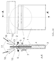
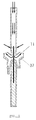
- Fig. 1a represents a schematic view (vertical cross-section and plan view) of an apparatus used to remove a liquid from the surfaces of a flat substrate according to a first embodiment of the invention.
- Fig. 1b shows an enlarged detail of the apparatus of figure 1a.
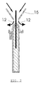
- Fig. 2 represents an alternative supply of gas towards a substrate, in an apparatus according to the invention
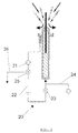
- Fig. 3 represents a liquid circuit in connection with an apparatus according to the invention.
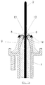
- Fig. 4 represents a schematic view (vertical cross-section) of an apparatus according to a second embodiment of the invention.
- Fig. 5 represents an apparatus according to the invention wherein the drying process is sealed from the atmosphere.
- Fig. 6a to 6d illustrate apparatuses according to the invention for treating and drying a batch of substrates.
- Fig. 7 represents an apparatus according to the invention, for treating and drying a continuous foil-like substrate.
- Fig. 8 represents a mechanism according to the invention for moving a substrate through an apparatus of the invention.
- Fig. 9a and 9b represent two embodiments of an apparatus of the invention, wherein a last droplet is removed.
- Fig. 10 represents a detailed view of a preferred embodiment of an apparatus according to the present invention.
- the present invention is firstly related to a method for liquid treating and drying a substrate.
- this substrate is a semiconductor wafer. It can also be a glass slice, a foil or film or tape, or even a wire.
- the treatment comprises one or more steps whereby the substrate is immersed in a liquid present inside a tank. Possibly, several of such steps, e.g. cleaning or etching, are performed while the substrate remains inside said tank, while the tank is consecutively filled with a number of treatment liquids.
- FIG. 1a A preferred embodiment of such a tank 1 for treating and drying a single flat substrate, according to the invention is shown in figure 1a.
- This particular tank is essentially flat and has a narrow opening or 'slit' 5 at the top.
- the substrate is then introduced in this tank. This may be done by lowering the substrate through said slit 5.
- the tank may possess a similar opening at the bottom through which the substrate may be introduced.
- Other ways of introducing a substrate in the tank 1 are within the scope of the present invention.
- the substrate 2 is to be removed from the tank and dried, i.e. all remaining liquid is to be removed from the substrate's surfaces.
- This drying forms the characteristic part of the present invention.
- the substrate is lifted up and moved through the slit 5, in a direction parallel to the surfaces that are to be dried.
- this slit is sufficiently narrow so that liquid overflows from the tank while the substrate is moving through the slit.
- a liquid surface 8 (see detail in figure 1b) is formed outside the tank 1 and a clear intersection line 12 develops between the substrate 2 and said overflowing liquid's surface 8.
- Characteristic to this embodiment is the fact that there is a unidirectional flow 14 in those parts of the opening's 5 cross section between the tank edges and the moving substrate, see figure 1b. This prevents the build-up of particles in the opening and avoids a stagnant liquid surface that may become saturated by tensio-active gas.
- the form of the tank's cross section leading up to the opening 5 is designed in a convergent way, so that the liquid flow is non-turbulent, resulting in a steady and uni-directional flow of liquid throughout the removal step.
- the drying is then obtained by causing a tensio-active effect or surface tension gradient (STG), i.e. a local reduction of the liquid's surface tension at the edges of the liquid body, to take place in every point along the length of this intersection line 12, and preferably on the intersection lines 12 on both sides of the substrate.
- STG surface tension gradient
- this is done by a uniform flow of a gaseous tensio-active substance, directed at the intersection line 12.
- Characteristic to the invention is the fact that the plane containing both the speed vector of this flow and of the substrate movement is perpendicular to the surface to be dried. This is the plane of the drawing in figure 1, the gas flow being indicated by reference 11.
- this flow is produced by a suitable device such as the nozzles 10, through narrow openings 13, which are parallel to the substrate surfaces.
- the flow produced through these openings has the same speed, pressure and direction in every point of the narrow openings 13, hence the word 'uniform'.
- the speed of the flow is equal in every point along a line on the substrate, parallel to the slit 13.
- the intersection line 12 preferably falls together with such a line parallel to the slit 13, and forms a straight 'drying front', i.e. a clear separation line between wet and dry surface.
- the gas can be heated so that its temperature is higher than that of the liquid.
- a uniform gas flow as described above is beneficial for the drying process : a sufficient gas velocity enhances the transfer of tensio-active species from the gas flow to the liquid at the drying front.
- the surface tension gradient is obtained by a heat supply directed at the intersection lines 12, heat being supplied along a line which is perpendicular to the substrate movement and parallel to the substrate in case of a flat substrate 2.
- a heat supply is produced by a suitable source, for example a hot filament, along a line parallel to the substrate's flat surfaces. The heat produced is the same in every point of said line, so that the heat supply and subsequent tensio-active effect is equally uniform, and able to create a straight drying front.
- the gas flow and heat supply described above may be combined.
- the tensio-active effect might differ along the drying front. This might be done by supplying a gas flow with a predefined speed profile along the length of the slit 13. In all cases however, the flow speed remains in a plane perpendicular to the surfaces to be dried.
- the speed of the drying process of the invention may be increased compared to existing methods.
- the speed and pressure of the drying gas flow can readily be adapted so that at a required high removal speed of the substrate, an efficient drying process is ensured.
- the method preferably further comprises an additional step wherein the last remaining liquid attached to the substrate after the drying step, is removed through evapouration.
- the substrate is held stationary for a period of time. This can also be done by bringing the stationary substrate into contact with a gas flow, preferably a heated gas flow, which is parallel to the substrate surface.
- a last step may be added, whereby a droplet is removed from the last part of the substrate that leaves the tank, by bringing said last part in contact with an object, such as a fiber or a piece of foam.
- the method can be applied to a batch of parallel substrates immersed in one tank, said tank having a number of openings 5, see figure 6a.
- the method described above is applicable to every individual substrate in such a batch.
- the method may be applied to a flat substrate or preferably a batch of substrates, while no overflow takes place between the flat surfaces of the substrate(s) and the neighboring sides of the tank, but only between the edges of the substrate and the tank (see figure 6b).
- the method applies, as long as a uniform surface tension reduction takes place at all the intersection lines 12 between substrates and liquid.
- the only difference with previous embodiments is that no overflow takes place at these intersection lines.
- the STG is then performed by the same means (gas flow and/or heat supply) as previously described.
- FIG. 1a shows a vertical cross section and frontal view of an apparatus for treatment of a single substrate according to a first embodiment of the invention.
- Figure 1b is an enlargement of a portion of the vertical cross section of fig. 1a.
- the apparatus comprises a flat tank 1, which is preferably capable of containing a substrate 2 in its totality.
- the tank 1 comprises at least one hole 3, through which it may be filled with a liquid 4.
- a slit 5 At the top of the tank is a slit 5, which is a narrow opening broad enough to allow the passage of the substrate 2, as illustrated.
- the length of the slit 5 is sufficient to let a substrate pass through.
- All around the tank, a gutter 6 is present, from which a drain 7 extends.
- the liquid 4 can be any type of cleaning or rinsing solution, an etching liquid or any other processing liquid known in the art.
- the tank is designed in order to have a low turbulence liquid flow through the slit 5, creating a liquid surface 8 in the vicinity of the substrate.
- This is optimized by the particular shape of the top part 9 of the tank, as seen in a cross-section perpendicular to the substrate surface, such as shown in figure 1a and 1b.
- the width of the tank is gradually reduced to the width of the opening 5.
- This converging width is designed so as to maintain a non-turbulent and uni-directional flow, described above.
- the slit 5 has parallel sides, and the width of the slit is at least twice the thickness of the substrate 2. This width is generally larger than in prior art devices which allow no overflow, thereby solving some of the problems related to such existing devices : bow phenomenon, etc...
- a supply of liquid to the tank is available, e.g. through the hole 3 or through other holes (not shown) in the tank 1.
- the liquid that appears at the top through the slit 5 is collected in the gutter 6 and removed by the drain 7.
- Means 10 are provided to direct a uniform flow 11 of a gaseous substance - on each side of the substrate - towards the drying front 12, which is the intersection line between the substrate 2 and the liquid's surface 8, as the liquid overflows from the tank.
- the gaseous substance, or 'drying ambient' may consist of :
- the means to direct the gas flow are such that uniform flows of gas are directed at the drying fronts 12 between the liquid surface 8 and the substrate 2, meaning that the gas flow has the same speed and direction at each point of a straight drying front.
- nozzles 10 may be used, which produce the flow in the vicinity of the drying front 12, through narrow slits 13 parallel to said front 12 and having at least the length of said front 12. In every point of the slits 13, the speed, pressure and direction of the produced gas flow are equal.
- the gaseous mixture should arrive at the drying front 12 with sufficient speed, so that an efficient transport or transfer of the mixture to the liquid at the drying front can take place.
- the main advantage of this type of flow is that it takes place in a uniform way across the entire drying front.
- the drying action of the gas will be the same, leading to a very efficient drying process.
- This allows to increase the speed at which the substrates are moved out of the tank, and hence the overall process speed.
- the speed at which the substrate is removed is at least 15mm/s.
- the gas supply rate for such a substrate, 20 cm in diameter, is 5 standard liter per minute, through a slit 13 of 1 mm in width.
- the angle between the nozzles' center lines 16 and the plane of the substrate is such that an optimal mixing of the gaseous mixture and the liquid is obtained.
- Other geometrical aspects of the nozzles 10 other than the slits 13, may alter without leaving the scope of the present invention.
- Fig. 2 shows an alternative means for supplying the drying ambient.
- two tilted side walls 15 guide the uniform flow of drying ambient towards the drying fronts 12.
- FIG. 3 shows a possible set-up of a liquid circuit 20 connected to the apparatus of the invention.
- This circuit comprises a pump 21, a filter 22, a valve 23.
- the filter removes particles from the liquid after which said liquid flows back to the tank 1 to be re-used.
- Such a circuit preferably accompanies a separate supply of fresh liquid 24, which ensures that the level of the liquid surface 8 remains stationary.
- a valve 25 is preferably present to regulate the amount of liquid that is recuperated and the amount that is diverted towards a drain 26.
- the recuperation of liquid by the circuit 20 may be undesirable for certain processes wherein no contamination whatsoever of the cleaning liquid is allowed. In that case, the overflowing liquid would flow into a drain or a separate waste collection tank, without being recirculated.
- a recirculation circuit such as the circuit 20 may be added to any of the embodiments according to the present invention.
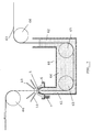
- FIG 4 shows another embodiment of an apparatus according to the invention. It comprises the same tank 1 as in the previous embodiment. Now however, a container 30 is placed directly above the first tank. This container has a narrow opening 31 at the bottom through which the substrate can enter. The drying ambient is injected through one or more holes 32 at the top of this container 30. In addition, drying ambient of the same or of other composition is injected through the walls of the container 30, preferably through long inlets 33 placed near the bottom of the container 30 and pointing downwards so that the gas flowing through these inlets 33 directs the flow downward. The flow through the inlets 33 should be uniform for the whole of the drying fronts 12, as described for the previous embodiments.
- the portion 34 at the bottom of the container 30 is preferably converging towards the opening 31 to obtain a smooth and stable flow of drying ambient through the opening 31 and towards the drying front 12 between the liquid surface and the substrate surface.
- This set-up with double injection (through openings 32 and 33) of drying ambient allows to create in the upper tank an environment with very low concentration of the vapours of the liquid to be removed, resulting in fast "evapouration" of the very small amount of liquid potentially adsorbed on the surface or present in microscopically small trenches even after macroscopic removal of the liquid from the substrate.
- This evapouration step then takes place while the substrate is held stationary in the container 30.
- the gas flow through the top openings 32 may be maintained while the substrate is held in the upper tank.
- the flow of gas parallel to the substrate then helps to remove the last remaining liquid adsorbed to the surfaces.
- a relatively hot mixture ('hot' being with respect to the liquid) of an inert gas, e.g. N 2 without any or with very little tensioactive vapour is injected, while at the lower inlets 33 a less heated mixture of an inert gas, e.g. N 2 with a higher concentration of tensioactive vapour is injected.
- an inert gas e.g. N 2 without any or with very little tensioactive vapour
- a less heated mixture of an inert gas e.g. N 2 with a higher concentration of tensioactive vapour
- an exhaust channel 35 can be provided to remove the drying ambient from the drying fronts 12.
- the exhaust channel is formed by an extension 36 of the container, and a structure 37 surrounding the tank, and having one tilted side wall 38 and one vertical side wall 39, to guide the gas flow 11 away from the drying fronts 12.
- FIG 5 shows another embodiment, wherein the drying fronts 12 are sealed off from the atmosphere.
- the structure 37 is fixed to the tank 1, as an extension of the gutter 6. This device allows no mixture of the gas flow with the atmosphere, as was possible in the previous embodiment through the side opening between the gutter 6 and the structure 37.
- Some materials such as bare Si suffer from the formation of drying marks, which is a consequence of an oxidising agent, mainly O 2 originating from the atmosphere and entering the treatment liquid in which the substrate is immersed. This causes the formation of etching agents, such as SiO 2 . The danger is that these etching agents become trapped with minute amounts of liquid in microscopic trenches of the surface after the drying process. When finally, these last amounts of liquid are removed by evapouration, the etching agents leave small marks on the surface.
- the set-up of figure 5 allows to minimize the contact between the atmosphere and the liquid in the tank 1, if a sufficient speed and pressure of the gas flow 11 is maintained.
- the complete apparatus may equally be placed in an enclosure wherein the pressure is low or zero or wherein the partial pressure of an oxidising species is close to zero, to further ensure that no oxidising agents can reach the treatment liquid.
- the gas pressure and speed of the flow 11 must be sufficient in this case to maintain a stable liquid surface 8.
- this embodiment equally enables the use of toxic or dangerous chemicals either as the liquid or in the drying gas mixture.
- the embodiment of figures 1 and 2 may have the same type of exhaust fixed to the gutter 6. All apparatuses according to the present invention may be placed in a low pressure or zero pressure or partial pressure environment, or in a strictly inert ambient.
- the tank 1 can be equipped with temperature control (either heating or cooling) and transducers producing mechanical vibration of high frequency often referred to as "Megasonic” (e.g. 1 MHz range), in order to reduce the residual particle concentration on the substrate and/or on the tank walls.
- Temperatur control either heating or cooling
- transducers producing mechanical vibration of high frequency often referred to as "Megasonic” (e.g. 1 MHz range), in order to reduce the residual particle concentration on the substrate and/or on the tank walls.
- the movement of a substrate relative to an apparatus as described in the above embodiments need not necessarily take place in a vertical plane.
- the apparatuses may be tilted over a given angle. The only condition that needs to be met is that an overflow of the liquid and subsequent evacuation of said liquid needs to be possible, putting a limit on the tilt angle.
- Figure 6a shows an apparatus according to the invention capable of treating and drying several parallel substrates, i.e. a batch of substrates.
- the top of the tank 1 comprises a row of openings 5 which are analogous to the openings in single substrate devices of the invention.
- the overflowing liquid produced between the substrates is collected in the intermediate gutters 50 which are in connection with the drain 7.
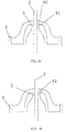
- Double nozzles 51 are present in between two substrates, in addition to the nozzles 10 at the sides of the tank, so that uniform flows of drying ambient are provided to all the drying fronts 12.
- the apparatus shown in figure 6b is different in that it allows the immersion of several flat and parallel substrates 2 in one liquid tank 1, without intermediate gutters.
- the overflow takes place between the short edges of the substrates and the sides, into gutters 52 and further into the drains 53.
- a single gutter might be used, surrounding the whole of the tank 1, but no overflow takes place over the edges of the tank which are parallel to the substrates.
- a uniform gas flow according to the invention is directed at every intersection line 12 between the substrate surfaces to be dried and the liquid. At these intersection lines, no overflow takes place in this embodiment.
- double nozzles 51 are placed in between two substrates, as well as single nozzles 54 at the sides. Some variants of the nozzles 51 are shown in figures 6c and 6d.
- FIG. 7 shows another embodiment of the invention, which is to be used for the treatment of continuous flexible substrates, such as films, foils, tapes or even wires.
- the tank 60 consists of two vertical legs 61 and 62.
- the top part of the leg 61 is similar to the top part of the tank 1 of previous embodiments, except that the width of the opening 5 is adapted to the width of the flexible substrate 63.
- the tank 60 has a horizontal part 64.
- the tank 60 is equipped with a system of guiding device, e.g. rollers 65 placed in said horizontal part 64. Rollers 66 outside the tank, working in synchronicity with the immersed rollers 65 ensure a continuous movement of the substrate 63 through the opening 5 at the top of the leg 61.
- Nozzles 10 are present for supplying a uniform flow of drying ambient towards the drying fronts on both sides of the substrate.
- a gutter 6 and drain 7 are present, just as in previous embodiments.
- a container 30 may be installed instead of the nozzles 10, analogous to the embodiment of figure 4.
- the tank 60 is filled by filling up the right leg 62, where a stable liquid level may be maintained, possibly with the help of level sensors or the like.
- This apparatus has the advantage that the fluid column in leg 62 allows an easy control of the level and pressure of the treatment liquid inside the tank 60.
- the rollers 65 could advantageously be replaced by liquid bearings to avoid friction between the rollers and the substrates.
- Such a liquid bearing might use the liquid 4 itself which would be circulated from the inside of the bearing to the outside through holes along the bearing's circumference, thereby maintaining the substrate at a fixed distance from the bearing's outer surface, and so avoiding direct contact and friction. Such friction may be the cause of particle generation.
- This apparatus may be used to clean and dry a row of parallel wires.
- the drying ambient was formed by gas flow, heated or not.
- the drying effect may be acquired by a heat source capable of very localized heating, in the region near the intersection line between a flat surface and a body of liquid present on said surface. Therefore, in stead of the nozzles 10 or 51, or the inlets 32 33 in the container 30, heat sources such as lasers or heat filaments may be placed on both sides of the tank, providing a uniform heat supply to the drying fronts 12. These heating means may be combined with the use of tensio-active gases or used as such. The heat sources should produce the same amount of heat in every point of a line parallel to the substrate surface.
- Figure 8 shows a preferred embodiment of the mechanism used for moving a single substrate through the opening 5 on top of the tank.
- a similar mechanism can be used for a batch of substrates.
- a support 80 is used underneath the substrate and inside the tank 1, in combination with a gripper device comprising three grippers 81.
- the support 80 pushes the substrate out of the tank 1.
- the latter is then gripped by the grippers 81 and pulled further out of the tank.
- the two grippers that are placed sideways of the substrate can move left to right (see arrow). They move inwards at a moment when more than half of the substrate has left the liquid bath.
- the top gripper moves downward (see arrow) to grip the top of the substrate.
- Both the support 80 and the three grippers 81 can move vertically up and down to produce an upward movement of the substrate at a constant or variable speed.
- the grippers and support can equally be used for lowering a substrate in the tank. It is preferable to have a smooth transition from a movement wherein the substrate is carried only by the support 80 to a movement wherein the substrate is carried only by the grippers 81.
- the support 80 will only retreat downwards after the grippers 81 have gripped the substrate and subsequently pull it out of the tank.
- a support having a sharp edge may be used, this edge reducing the contact zone between support and substrate to a minimum.
- a support having several contact zones along a semi-circle may be used to provide a more stable way of holding the substrate.
- An example of this is shown in figure 10. It is an advantage of the mechanism of figure 8, that the grippers 81 are never immersed in the liquid, and therefore remain dry at all times. Only the support 80 is constantly immersed. There are no gripping devices or supports which are immersed at one point and separated from the liquid at another : this avoids problems with liquid remaining at the contact zones with grippers or supports.
- the removal of the last droplet attached to the last part of the substrate leaving the tank can be done by optimising the shape of the slit 5 on top of the liquid tank, and reducing the vertical lift speed just before the substrate detaches from the liquid in the tank.
- a fiber which has a high affinity for the liquid.
- Figure 9a shows an enlarged view of such a fiber 90, which is close to the surface of the substrate 2 as the substrate moves upward, the fiber being attached to the top of the tank in point 91.
- Glass fibers are preferably used when the cleaning liquid is an aqueous solution. They can be placed on one or both sides of the slit 5. Also other materials such as spunge like foams could be useful (e.g.
- the droplet take-up device be it a fiber or a foam, are movably attached to the top of the tank, and are moved towards the substrate at the moment when the last part of the substrate passes the take-up device.
- Another solution for the removal of the last droplet is the local application of a small amount of a second liquid that displaces the first liquid and then readily evapourates, e.g. isopropyl alcohol.
- FIG 10 shows a detailed view of an apparatus according to the invention, in particular of the tank 1 for treating and cleaning a single substrate 2.
- the support 80 is visible. It is mounted on a slide 100, which can be pulled up with a handle 101.
- the hole 3 is visible for letting in liquid for compensating the overflow.
- the convergent cross section leading up to the slit 5 is equally apparent, as are the gutter 6 and drain 7.
- the nozzles or other means for creating surface tension gradient are not represented on this drawing.
Landscapes
- Engineering & Computer Science (AREA)
- Textile Engineering (AREA)
- Mechanical Engineering (AREA)
- General Engineering & Computer Science (AREA)
- Cleaning Or Drying Semiconductors (AREA)
- Drying Of Solid Materials (AREA)
- Manufacturing Of Printed Wiring (AREA)
Applications Claiming Priority (2)
| Application Number | Priority Date | Filing Date | Title |
|---|---|---|---|
| US21469300P | 2000-06-27 | 2000-06-27 | |
| US214693P | 2000-06-27 |
Publications (3)
| Publication Number | Publication Date |
|---|---|
| EP1168422A2 true EP1168422A2 (de) | 2002-01-02 |
| EP1168422A3 EP1168422A3 (de) | 2006-03-22 |
| EP1168422B1 EP1168422B1 (de) | 2009-12-16 |
Family
ID=22800074
Family Applications (1)
| Application Number | Title | Priority Date | Filing Date |
|---|---|---|---|
| EP01870138A Expired - Lifetime EP1168422B1 (de) | 2000-06-27 | 2001-06-26 | Verfahren und Vorrichtung zum Reinigen und Trocknen eines Substrats |
Country Status (5)
| Country | Link |
|---|---|
| US (2) | US6632751B2 (de) |
| EP (1) | EP1168422B1 (de) |
| JP (1) | JP4629270B2 (de) |
| AT (1) | ATE452419T1 (de) |
| DE (1) | DE60140780D1 (de) |
Cited By (8)
| Publication number | Priority date | Publication date | Assignee | Title |
|---|---|---|---|---|
| US6726848B2 (en) | 2001-12-07 | 2004-04-27 | Scp Global Technologies, Inc. | Apparatus and method for single substrate processing |
| US6875289B2 (en) | 2002-09-13 | 2005-04-05 | Fsi International, Inc. | Semiconductor wafer cleaning systems and methods |
| US7513062B2 (en) | 2001-11-02 | 2009-04-07 | Applied Materials, Inc. | Single wafer dryer and drying methods |
| WO2010026904A1 (en) * | 2008-09-03 | 2010-03-11 | Tonen Chemical Corporation | Apparatus and method for drying a thermoplastic sheet |
| US7718011B2 (en) | 1999-03-26 | 2010-05-18 | Applied Materials, Inc. | Apparatus for cleaning and drying substrates |
| US7775219B2 (en) | 2006-12-29 | 2010-08-17 | Applied Materials, Inc. | Process chamber lid and controlled exhaust |
| US7980255B2 (en) | 2001-11-02 | 2011-07-19 | Applied Materials, Inc. | Single wafer dryer and drying methods |
| DE102008061521B4 (de) * | 2008-12-10 | 2011-12-08 | Siltronic Ag | Verfahren zur Behandlung einer Halbleiterscheibe |
Families Citing this family (37)
| Publication number | Priority date | Publication date | Assignee | Title |
|---|---|---|---|---|
| US6826729B1 (en) * | 2001-06-29 | 2004-11-30 | Microsoft Corporation | Gallery user interface controls |
| US20070079932A1 (en) * | 2001-12-07 | 2007-04-12 | Applied Materials, Inc. | Directed purge for contact free drying of wafers |
| US20080000495A1 (en) * | 2001-12-07 | 2008-01-03 | Eric Hansen | Apparatus and method for single substrate processing |
| US20090029560A1 (en) * | 2001-12-07 | 2009-01-29 | Applied Materials, Inc. | Apparatus and method for single substrate processing |
| US20070272657A1 (en) * | 2001-12-07 | 2007-11-29 | Eric Hansen | Apparatus and method for single substrate processing |
| US20040031167A1 (en) | 2002-06-13 | 2004-02-19 | Stein Nathan D. | Single wafer method and apparatus for drying semiconductor substrates using an inert gas air-knife |
| US20040050408A1 (en) * | 2002-09-13 | 2004-03-18 | Christenson Kurt K. | Treatment systems and methods |
| KR100585476B1 (ko) | 2002-11-12 | 2006-06-07 | 에이에스엠엘 네델란즈 비.브이. | 리소그래피 장치 및 디바이스 제조방법 |
| US7793233B1 (en) | 2003-03-12 | 2010-09-07 | Microsoft Corporation | System and method for customizing note flags |
| US7454763B2 (en) * | 2003-03-26 | 2008-11-18 | Microsoft Corporation | System and method for linking page content with a video media file and displaying the links |
| US7707255B2 (en) | 2003-07-01 | 2010-04-27 | Microsoft Corporation | Automatic grouping of electronic mail |
| US8799808B2 (en) * | 2003-07-01 | 2014-08-05 | Microsoft Corporation | Adaptive multi-line view user interface |
| US7703036B2 (en) | 2004-08-16 | 2010-04-20 | Microsoft Corporation | User interface for displaying selectable software functionality controls that are relevant to a selected object |
| US8117542B2 (en) * | 2004-08-16 | 2012-02-14 | Microsoft Corporation | User interface for displaying selectable software functionality controls that are contextually relevant to a selected object |
| US8255828B2 (en) | 2004-08-16 | 2012-08-28 | Microsoft Corporation | Command user interface for displaying selectable software functionality controls |
| US8146016B2 (en) | 2004-08-16 | 2012-03-27 | Microsoft Corporation | User interface for displaying a gallery of formatting options applicable to a selected object |
| US7712049B2 (en) * | 2004-09-30 | 2010-05-04 | Microsoft Corporation | Two-dimensional radial user interface for computer software applications |
| US8070884B2 (en) * | 2005-04-01 | 2011-12-06 | Fsi International, Inc. | Methods for rinsing microelectronic substrates utilizing cool rinse fluid within a gas enviroment including a drying enhancement substance |
| US7530029B2 (en) * | 2005-05-24 | 2009-05-05 | Microsoft Corporation | Narrow mode navigation pane |
| US7845540B2 (en) * | 2005-08-30 | 2010-12-07 | Micron Technology, Inc. | Systems and methods for depositing conductive material into openings in microfeature workpieces |
| US8627222B2 (en) | 2005-09-12 | 2014-01-07 | Microsoft Corporation | Expanded search and find user interface |
| US7739259B2 (en) * | 2005-09-12 | 2010-06-15 | Microsoft Corporation | Integrated search and find user interface |
| WO2007047163A2 (en) * | 2005-10-04 | 2007-04-26 | Applied Materials, Inc. | Methods and apparatus for drying a substrate |
| US9727989B2 (en) | 2006-06-01 | 2017-08-08 | Microsoft Technology Licensing, Llc | Modifying and formatting a chart using pictorially provided chart elements |
| US20080236615A1 (en) * | 2007-03-28 | 2008-10-02 | Mimken Victor B | Method of processing wafers in a sequential fashion |
| US8484578B2 (en) | 2007-06-29 | 2013-07-09 | Microsoft Corporation | Communication between a document editor in-space user interface and a document editor out-space user interface |
| US8762880B2 (en) | 2007-06-29 | 2014-06-24 | Microsoft Corporation | Exposing non-authoring features through document status information in an out-space user interface |
| JP4994990B2 (ja) * | 2007-08-03 | 2012-08-08 | 東京エレクトロン株式会社 | 基板処理方法、基板処理装置、プログラム、記録媒体および置換剤 |
| JP2009081366A (ja) * | 2007-09-27 | 2009-04-16 | Elpida Memory Inc | バッチ処理装置 |
| US9588781B2 (en) | 2008-03-31 | 2017-03-07 | Microsoft Technology Licensing, Llc | Associating command surfaces with multiple active components |
| US9665850B2 (en) | 2008-06-20 | 2017-05-30 | Microsoft Technology Licensing, Llc | Synchronized conversation-centric message list and message reading pane |
| KR101421752B1 (ko) * | 2008-10-21 | 2014-07-22 | 도쿄엘렉트론가부시키가이샤 | 기판 처리 장치 및 기판 처리 방법 |
| JP5491518B2 (ja) * | 2008-11-25 | 2014-05-14 | スリーエム イノベイティブ プロパティズ カンパニー | 可撓性ウェブ洗浄用装置及び方法 |
| EP2381310B1 (de) | 2010-04-22 | 2015-05-06 | ASML Netherlands BV | Flüssigkeitshandhabungsstruktur und lithographischer Apparat |
| US8732978B2 (en) * | 2011-06-02 | 2014-05-27 | Yuji Richard Kuan | Drying silicon particles and recovering solvent |
| US9449862B2 (en) * | 2011-06-03 | 2016-09-20 | Tel Nexx, Inc. | Parallel single substrate processing system |
| US10283396B2 (en) * | 2016-06-27 | 2019-05-07 | Asm Nexx, Inc. | Workpiece holder for a wet processing system |
Family Cites Families (34)
| Publication number | Priority date | Publication date | Assignee | Title |
|---|---|---|---|---|
| US3865298A (en) * | 1973-08-14 | 1975-02-11 | Atomic Energy Commission | Solder leveling |
| US4483040A (en) * | 1982-12-22 | 1984-11-20 | International Business Machines Corporation | In-line mask cleaning system |
| US4569695A (en) * | 1983-04-21 | 1986-02-11 | Nec Corporation | Method of cleaning a photo-mask |
| NL8900480A (nl) * | 1989-02-27 | 1990-09-17 | Philips Nv | Werkwijze en inrichting voor het drogen van substraten na behandeling in een vloeistof. |
| JPH03256326A (ja) * | 1990-03-06 | 1991-11-15 | Hitachi Ltd | 処理装置 |
| JPH04151835A (ja) * | 1990-05-25 | 1992-05-25 | Shimada Phys & Chem Ind Co Ltd | 洗浄乾燥方法 |
| JPH04283925A (ja) * | 1991-03-12 | 1992-10-08 | Hitachi Ltd | 洗浄乾燥装置 |
| JPH05102121A (ja) * | 1991-10-02 | 1993-04-23 | Sugai:Kk | 枚葉式洗浄方法及び装置 |
| JP2840799B2 (ja) * | 1991-10-02 | 1998-12-24 | 株式会社スガイ | 枚葉式洗浄方法及び装置 |
| JP2920165B2 (ja) * | 1991-11-29 | 1999-07-19 | エス・イー・エス株式会社 | 枚葉洗浄用オーバーフロー槽 |
| JPH07249605A (ja) * | 1994-03-11 | 1995-09-26 | Dainippon Screen Mfg Co Ltd | 基板洗浄装置 |
| DE4413077C2 (de) * | 1994-04-15 | 1997-02-06 | Steag Micro Tech Gmbh | Verfahren und Vorrichtung zur chemischen Behandlung von Substraten |
| US5571337A (en) * | 1994-11-14 | 1996-11-05 | Yieldup International | Method for cleaning and drying a semiconductor wafer |
| US5660642A (en) * | 1995-05-26 | 1997-08-26 | The Regents Of The University Of California | Moving zone Marangoni drying of wet objects using naturally evaporated solvent vapor |
| JP3333830B2 (ja) * | 1995-07-27 | 2002-10-15 | 株式会社タクマ | 基板のリンス及び乾燥の方法及び装置 |
| US5714203A (en) * | 1995-08-23 | 1998-02-03 | Ictop Entwicklungs Gmbh | Procedure for the drying of silicon |
| EP0817246B1 (de) * | 1996-06-24 | 2005-02-02 | Interuniversitair Microelektronica Centrum Vzw | Vorrichtung und Verfahren zur Nassreinigung oder zum Ätzen eines flachen Substrats |
| US6050275A (en) * | 1996-09-27 | 2000-04-18 | Tokyo Electron Limited | Apparatus for and method of cleaning objects to be processed |
| JPH10189528A (ja) * | 1996-12-27 | 1998-07-21 | Dainippon Screen Mfg Co Ltd | 基板洗浄装置および基板洗浄方法 |
| JP3151613B2 (ja) * | 1997-06-17 | 2001-04-03 | 東京エレクトロン株式会社 | 洗浄・乾燥処理方法及びその装置 |
| US5884640A (en) * | 1997-08-07 | 1999-03-23 | Applied Materials, Inc. | Method and apparatus for drying substrates |
| US6354311B1 (en) * | 1997-09-10 | 2002-03-12 | Dainippon Screen Mfg. Co., Ltd. | Substrate drying apparatus and substrate processing apparatus |
| US6138698A (en) * | 1997-11-20 | 2000-10-31 | Tokyo Electron Limited | Ultrasonic cleaning apparatus |
| JPH11257851A (ja) * | 1998-03-10 | 1999-09-24 | Tokyo Electron Ltd | 乾燥装置及び乾燥方法 |
| JPH11277011A (ja) * | 1998-03-31 | 1999-10-12 | Shibaura Mechatronics Corp | エアナイフ及びエアナイフを用いた処理装置 |
| US6216709B1 (en) * | 1998-09-04 | 2001-04-17 | Komag, Inc. | Method for drying a substrate |
| US6199564B1 (en) * | 1998-11-03 | 2001-03-13 | Tokyo Electron Limited | Substrate processing method and apparatus |
| US6119708A (en) * | 1998-11-11 | 2000-09-19 | Applied Materials, Inc. | Method and apparatus for cleaning the edge of a thin disc |
| JP3658257B2 (ja) * | 1998-12-24 | 2005-06-08 | キヤノン株式会社 | 洗浄方法及び洗浄装置及び電子写真感光体及び電子写真感光体の製造方法 |
| US6328814B1 (en) * | 1999-03-26 | 2001-12-11 | Applied Materials, Inc. | Apparatus for cleaning and drying substrates |
| JP3448613B2 (ja) * | 1999-06-29 | 2003-09-22 | オメガセミコン電子株式会社 | 乾燥装置 |
| FR2797405B1 (fr) * | 1999-08-12 | 2001-10-26 | Coillard Sa Ets | Bac de rincage a liquide ultra propre |
| US6192600B1 (en) * | 1999-09-09 | 2001-02-27 | Semitool, Inc. | Thermocapillary dryer |
| US6530388B1 (en) * | 2000-02-15 | 2003-03-11 | Quantum Global Technologies, Llc | Volume efficient cleaning systems |
-
2001
- 2001-06-26 EP EP01870138A patent/EP1168422B1/de not_active Expired - Lifetime
- 2001-06-26 DE DE60140780T patent/DE60140780D1/de not_active Expired - Lifetime
- 2001-06-26 AT AT01870138T patent/ATE452419T1/de not_active IP Right Cessation
- 2001-06-27 US US09/892,269 patent/US6632751B2/en not_active Expired - Lifetime
- 2001-06-27 JP JP2001195403A patent/JP4629270B2/ja not_active Expired - Lifetime
-
2003
- 2003-07-09 US US10/617,288 patent/US6910487B2/en not_active Expired - Lifetime
Cited By (10)
| Publication number | Priority date | Publication date | Assignee | Title |
|---|---|---|---|---|
| US7718011B2 (en) | 1999-03-26 | 2010-05-18 | Applied Materials, Inc. | Apparatus for cleaning and drying substrates |
| US7513062B2 (en) | 2001-11-02 | 2009-04-07 | Applied Materials, Inc. | Single wafer dryer and drying methods |
| US7980255B2 (en) | 2001-11-02 | 2011-07-19 | Applied Materials, Inc. | Single wafer dryer and drying methods |
| US6726848B2 (en) | 2001-12-07 | 2004-04-27 | Scp Global Technologies, Inc. | Apparatus and method for single substrate processing |
| US6875289B2 (en) | 2002-09-13 | 2005-04-05 | Fsi International, Inc. | Semiconductor wafer cleaning systems and methods |
| US7775219B2 (en) | 2006-12-29 | 2010-08-17 | Applied Materials, Inc. | Process chamber lid and controlled exhaust |
| WO2010026904A1 (en) * | 2008-09-03 | 2010-03-11 | Tonen Chemical Corporation | Apparatus and method for drying a thermoplastic sheet |
| DE102008061521B4 (de) * | 2008-12-10 | 2011-12-08 | Siltronic Ag | Verfahren zur Behandlung einer Halbleiterscheibe |
| US8372213B2 (en) | 2008-12-10 | 2013-02-12 | Siltronic Ag | Method for the treatment of a semiconductor wafer |
| US8580046B2 (en) | 2008-12-10 | 2013-11-12 | Siltronic Ag | Method for the treatment of a semiconductor wafer |
Also Published As
| Publication number | Publication date |
|---|---|
| US6632751B2 (en) | 2003-10-14 |
| US20020016082A1 (en) | 2002-02-07 |
| ATE452419T1 (de) | 2010-01-15 |
| JP2002164319A (ja) | 2002-06-07 |
| DE60140780D1 (de) | 2010-01-28 |
| US20040010933A1 (en) | 2004-01-22 |
| JP4629270B2 (ja) | 2011-02-09 |
| US6910487B2 (en) | 2005-06-28 |
| EP1168422A3 (de) | 2006-03-22 |
| EP1168422B1 (de) | 2009-12-16 |
Similar Documents
| Publication | Publication Date | Title |
|---|---|---|
| EP1168422B1 (de) | Verfahren und Vorrichtung zum Reinigen und Trocknen eines Substrats | |
| US6875289B2 (en) | Semiconductor wafer cleaning systems and methods | |
| US10473396B2 (en) | Wafer dryer apparatus and method | |
| JP4296090B2 (ja) | 枚葉式のウエハ乾燥装置及び乾燥方法 | |
| US7437834B2 (en) | Method of processing substrate and substrate processing apparatus | |
| JP3448613B2 (ja) | 乾燥装置 | |
| US7648580B2 (en) | Substrate processing method and substrate processing device | |
| CA2630885A1 (en) | Apparatus and method for wet-chemical processing of flat, thin substrates in a continuous method | |
| KR20210028274A (ko) | 금속 도금 전에 기판들의 화학적 그리고 가열된 습윤을 위한 시스템 및 방법 | |
| US6799588B1 (en) | Apparatus for treating substrates | |
| JP4007980B2 (ja) | 基板乾燥方法及び基板乾燥装置 | |
| KR20040008059A (ko) | 기판 세정 방법 및 이를 이용한 기판 세정 장치 | |
| JP2006080420A (ja) | 基板処理法及び基板処理装置 | |
| JP3600746B2 (ja) | 基板処理装置 | |
| JP3450200B2 (ja) | 基板処理装置 | |
| JPH0453228A (ja) | 半導体基板処理装置 |
Legal Events
| Date | Code | Title | Description |
|---|---|---|---|
| PUAI | Public reference made under article 153(3) epc to a published international application that has entered the european phase |
Free format text: ORIGINAL CODE: 0009012 |
|
| AK | Designated contracting states |
Kind code of ref document: A2 Designated state(s): AT BE CH CY DE DK ES FI FR GB GR IE IT LI LU MC NL PT SE TR |
|
| AX | Request for extension of the european patent |
Free format text: AL;LT;LV;MK;RO;SI |
|
| PUAL | Search report despatched |
Free format text: ORIGINAL CODE: 0009013 |
|
| AK | Designated contracting states |
Kind code of ref document: A3 Designated state(s): AT BE CH CY DE DK ES FI FR GB GR IE IT LI LU MC NL PT SE TR |
|
| AX | Request for extension of the european patent |
Extension state: AL LT LV MK RO SI |
|
| RIC1 | Information provided on ipc code assigned before grant |
Ipc: F26B 3/04 20060101ALI20060202BHEP Ipc: B08B 7/04 20060101ALI20060202BHEP Ipc: B05D 3/04 20060101ALI20060202BHEP Ipc: H01L 21/00 20060101AFI20011009BHEP |
|
| 17P | Request for examination filed |
Effective date: 20060907 |
|
| AKX | Designation fees paid |
Designated state(s): AT BE CH CY DE DK ES FI FR GB GR IE IT LI LU MC NL PT SE TR |
|
| 17Q | First examination report despatched |
Effective date: 20070127 |
|
| R17C | First examination report despatched (corrected) |
Effective date: 20070427 |
|
| GRAP | Despatch of communication of intention to grant a patent |
Free format text: ORIGINAL CODE: EPIDOSNIGR1 |
|
| RAP1 | Party data changed (applicant data changed or rights of an application transferred) |
Owner name: IMEC |
|
| GRAS | Grant fee paid |
Free format text: ORIGINAL CODE: EPIDOSNIGR3 |
|
| GRAA | (expected) grant |
Free format text: ORIGINAL CODE: 0009210 |
|
| AK | Designated contracting states |
Kind code of ref document: B1 Designated state(s): AT BE CH CY DE DK ES FI FR GB GR IE IT LI LU MC NL PT SE TR |
|
| REG | Reference to a national code |
Ref country code: GB Ref legal event code: FG4D |
|
| REG | Reference to a national code |
Ref country code: CH Ref legal event code: EP |
|
| REG | Reference to a national code |
Ref country code: IE Ref legal event code: FG4D |
|
| REF | Corresponds to: |
Ref document number: 60140780 Country of ref document: DE Date of ref document: 20100128 Kind code of ref document: P |
|
| REG | Reference to a national code |
Ref country code: NL Ref legal event code: VDEP Effective date: 20091216 |
|
| PG25 | Lapsed in a contracting state [announced via postgrant information from national office to epo] |
Ref country code: SE Free format text: LAPSE BECAUSE OF FAILURE TO SUBMIT A TRANSLATION OF THE DESCRIPTION OR TO PAY THE FEE WITHIN THE PRESCRIBED TIME-LIMIT Effective date: 20091216 Ref country code: FI Free format text: LAPSE BECAUSE OF FAILURE TO SUBMIT A TRANSLATION OF THE DESCRIPTION OR TO PAY THE FEE WITHIN THE PRESCRIBED TIME-LIMIT Effective date: 20091216 |
|
| PG25 | Lapsed in a contracting state [announced via postgrant information from national office to epo] |
Ref country code: AT Free format text: LAPSE BECAUSE OF FAILURE TO SUBMIT A TRANSLATION OF THE DESCRIPTION OR TO PAY THE FEE WITHIN THE PRESCRIBED TIME-LIMIT Effective date: 20091216 |
|
| PG25 | Lapsed in a contracting state [announced via postgrant information from national office to epo] |
Ref country code: PT Free format text: LAPSE BECAUSE OF FAILURE TO SUBMIT A TRANSLATION OF THE DESCRIPTION OR TO PAY THE FEE WITHIN THE PRESCRIBED TIME-LIMIT Effective date: 20100416 Ref country code: NL Free format text: LAPSE BECAUSE OF FAILURE TO SUBMIT A TRANSLATION OF THE DESCRIPTION OR TO PAY THE FEE WITHIN THE PRESCRIBED TIME-LIMIT Effective date: 20091216 Ref country code: ES Free format text: LAPSE BECAUSE OF FAILURE TO SUBMIT A TRANSLATION OF THE DESCRIPTION OR TO PAY THE FEE WITHIN THE PRESCRIBED TIME-LIMIT Effective date: 20100327 |
|
| PG25 | Lapsed in a contracting state [announced via postgrant information from national office to epo] |
Ref country code: BE Free format text: LAPSE BECAUSE OF FAILURE TO SUBMIT A TRANSLATION OF THE DESCRIPTION OR TO PAY THE FEE WITHIN THE PRESCRIBED TIME-LIMIT Effective date: 20091216 |
|
| PLBE | No opposition filed within time limit |
Free format text: ORIGINAL CODE: 0009261 |
|
| STAA | Information on the status of an ep patent application or granted ep patent |
Free format text: STATUS: NO OPPOSITION FILED WITHIN TIME LIMIT |
|
| PG25 | Lapsed in a contracting state [announced via postgrant information from national office to epo] |
Ref country code: GR Free format text: LAPSE BECAUSE OF FAILURE TO SUBMIT A TRANSLATION OF THE DESCRIPTION OR TO PAY THE FEE WITHIN THE PRESCRIBED TIME-LIMIT Effective date: 20100317 Ref country code: CY Free format text: LAPSE BECAUSE OF FAILURE TO SUBMIT A TRANSLATION OF THE DESCRIPTION OR TO PAY THE FEE WITHIN THE PRESCRIBED TIME-LIMIT Effective date: 20091216 |
|
| 26N | No opposition filed |
Effective date: 20100917 |
|
| PG25 | Lapsed in a contracting state [announced via postgrant information from national office to epo] |
Ref country code: MC Free format text: LAPSE BECAUSE OF NON-PAYMENT OF DUE FEES Effective date: 20100630 Ref country code: DK Free format text: LAPSE BECAUSE OF FAILURE TO SUBMIT A TRANSLATION OF THE DESCRIPTION OR TO PAY THE FEE WITHIN THE PRESCRIBED TIME-LIMIT Effective date: 20091216 |
|
| REG | Reference to a national code |
Ref country code: CH Ref legal event code: PL |
|
| PG25 | Lapsed in a contracting state [announced via postgrant information from national office to epo] |
Ref country code: IT Free format text: LAPSE BECAUSE OF FAILURE TO SUBMIT A TRANSLATION OF THE DESCRIPTION OR TO PAY THE FEE WITHIN THE PRESCRIBED TIME-LIMIT Effective date: 20091216 |
|
| PG25 | Lapsed in a contracting state [announced via postgrant information from national office to epo] |
Ref country code: CH Free format text: LAPSE BECAUSE OF NON-PAYMENT OF DUE FEES Effective date: 20100630 Ref country code: IE Free format text: LAPSE BECAUSE OF NON-PAYMENT OF DUE FEES Effective date: 20100626 Ref country code: LI Free format text: LAPSE BECAUSE OF NON-PAYMENT OF DUE FEES Effective date: 20100630 |
|
| PG25 | Lapsed in a contracting state [announced via postgrant information from national office to epo] |
Ref country code: LU Free format text: LAPSE BECAUSE OF NON-PAYMENT OF DUE FEES Effective date: 20100626 |
|
| PG25 | Lapsed in a contracting state [announced via postgrant information from national office to epo] |
Ref country code: TR Free format text: LAPSE BECAUSE OF FAILURE TO SUBMIT A TRANSLATION OF THE DESCRIPTION OR TO PAY THE FEE WITHIN THE PRESCRIBED TIME-LIMIT Effective date: 20091216 |
|
| REG | Reference to a national code |
Ref country code: FR Ref legal event code: PLFP Year of fee payment: 16 |
|
| REG | Reference to a national code |
Ref country code: FR Ref legal event code: PLFP Year of fee payment: 17 |
|
| REG | Reference to a national code |
Ref country code: FR Ref legal event code: PLFP Year of fee payment: 18 |
|
| PGFP | Annual fee paid to national office [announced via postgrant information from national office to epo] |
Ref country code: DE Payment date: 20200519 Year of fee payment: 20 Ref country code: FR Payment date: 20200520 Year of fee payment: 20 |
|
| PGFP | Annual fee paid to national office [announced via postgrant information from national office to epo] |
Ref country code: GB Payment date: 20200525 Year of fee payment: 20 |
|
| REG | Reference to a national code |
Ref country code: DE Ref legal event code: R071 Ref document number: 60140780 Country of ref document: DE |
|
| REG | Reference to a national code |
Ref country code: GB Ref legal event code: PE20 Expiry date: 20210625 |
|
| PG25 | Lapsed in a contracting state [announced via postgrant information from national office to epo] |
Ref country code: GB Free format text: LAPSE BECAUSE OF EXPIRATION OF PROTECTION Effective date: 20210625 |