EP1166358B1 - Verfahren zum abtragen von dünnen schichten auf einem trägermaterial - Google Patents
Verfahren zum abtragen von dünnen schichten auf einem trägermaterial Download PDFInfo
- Publication number
- EP1166358B1 EP1166358B1 EP00925180A EP00925180A EP1166358B1 EP 1166358 B1 EP1166358 B1 EP 1166358B1 EP 00925180 A EP00925180 A EP 00925180A EP 00925180 A EP00925180 A EP 00925180A EP 1166358 B1 EP1166358 B1 EP 1166358B1
- Authority
- EP
- European Patent Office
- Prior art keywords
- thin
- substrate
- layer
- layers
- light pulses
- Prior art date
- Legal status (The legal status is an assumption and is not a legal conclusion. Google has not performed a legal analysis and makes no representation as to the accuracy of the status listed.)
- Expired - Lifetime
Links
Images

Classifications
-
- B—PERFORMING OPERATIONS; TRANSPORTING
- B23—MACHINE TOOLS; METAL-WORKING NOT OTHERWISE PROVIDED FOR
- B23K—SOLDERING OR UNSOLDERING; WELDING; CLADDING OR PLATING BY SOLDERING OR WELDING; CUTTING BY APPLYING HEAT LOCALLY, e.g. FLAME CUTTING; WORKING BY LASER BEAM
- B23K26/00—Working by laser beam, e.g. welding, cutting or boring
- B23K26/08—Devices involving relative movement between laser beam and workpiece
- B23K26/083—Devices involving movement of the workpiece in at least one axial direction
- B23K26/0853—Devices involving movement of the workpiece in at least two axial directions, e.g. in a plane
-
- B—PERFORMING OPERATIONS; TRANSPORTING
- B23—MACHINE TOOLS; METAL-WORKING NOT OTHERWISE PROVIDED FOR
- B23K—SOLDERING OR UNSOLDERING; WELDING; CLADDING OR PLATING BY SOLDERING OR WELDING; CUTTING BY APPLYING HEAT LOCALLY, e.g. FLAME CUTTING; WORKING BY LASER BEAM
- B23K26/00—Working by laser beam, e.g. welding, cutting or boring
- B23K26/36—Removing material
- B23K26/361—Removing material for deburring or mechanical trimming
-
- H—ELECTRICITY
- H10—SEMICONDUCTOR DEVICES; ELECTRIC SOLID-STATE DEVICES NOT OTHERWISE PROVIDED FOR
- H10F—INORGANIC SEMICONDUCTOR DEVICES SENSITIVE TO INFRARED RADIATION, LIGHT, ELECTROMAGNETIC RADIATION OF SHORTER WAVELENGTH OR CORPUSCULAR RADIATION
- H10F71/00—Manufacture or treatment of devices covered by this subclass
Definitions
- the invention relates to a method for removing thin layers on a carrier material.
- the invention is directed to the removal of surface layers of a thin-film solar cell. Moreover, the invention relates to a method for encapsulating a thin-film solar module consisting of a substrate coated with thin layers.
- thin film solar cells As an alternative to these conventional solar modules, thin film solar cells have become known which are based on layer thicknesses in the micrometer range.
- the essential elements of a thin-film solar cell are in Fig. 2 are shown and consist of a p / n junction between the absorber layer and the window layer.
- thin-film cells can be interconnected in an integrated manner: following individual coating steps on the total area, a) the back electrode b) the cell in between and c) the front electrode are subdivided into longitudinal strips. Will the three cuts be relative to each other offset laterally, forms an electrical connection between the front and back electrodes of adjacent cells.
- mechanical scribing or laser techniques can be used for the individual cuts. In this way, a standard solar module for 12 V applications can be produced inexpensively, for example, has an extension of about 0.5 x 0.5 m 2 .
- the lifetime of such a solar module is significantly influenced by how well the thin films are protected from weather and other environmental influences.
- the thin films In order to achieve the longest possible service life of 30 years or more, the thin films must be able to withstand the extreme effects of sun rays, moisture and air pollutants on a long-term basis.
- the requirements in terms of moisture stability and dielectric strength can therefore only be met if sufficient encapsulation of the thin-film solar cell and sufficient electrical insulation of the current-carrying components is ensured.
- the current-carrying components of a thin-film solar cell are encapsulated with a laminate.
- the encapsulation is achieved in that, after the substrate has been coated with the current-carrying layers, the edge region of the substrate is again stripped off and a laminate layer is then applied over the entire layer. This achieves a corrosion-resistant bonding of laminate layer and substrate in the edge region. Thus, the inner areas are reliably protected against moisture degradation.
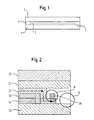
- Fig. 1 shows for clarity a schematic representation of a section through an encapsulated solar cell.
- layers 3 are applied, which decoates in the edge regions 5 and are encapsulated by a laminate layer 2.
- a layer of window glass 1 is applied over the laminate layer 2.
- a problem with such an encapsulation of a thin-film solar cell is the delamination of the thin layers in the edge region.
- Conventional decoating methods such as sandblasting or debinding with a grinding wheel, inevitably result in damage to the substrate edge and microcracks in this area. Due to the large temperature differences in an operating thin-film module and the resulting tensile stresses increases the risk of breakage, so that cracks in the edge area can eventually lead to damage to a solar cell.
- the edge deletion must therefore take place in the usually marginal area of a few millimeters to a few centimeters particularly gently.
- US 5 151 135 discloses a method of cleaning chemical, metallic and particulate contaminants from solid surfaces.
- the method comprises irradiating the surface with substantially ultraviolet laser radiation, in particular an excimer laser, wherein the laser beam may have a square spot of 0.25 cm 2 , with an optical homogenizer after US 4,733,944 is used.
- JP 10 052 780 A discloses an apparatus for laser etching.
- a laser beam is imaged over a series of mirrors, lenses and at least one gap, and another gap or diffuser plate on the workpiece.
- the invention is based on the finding that, in contrast to previously known applications, a laser ablation process can surprisingly also be used for ablation widths in the millimeter range.
- the working surface of the laser beam is extended over a suitable optical system in a range of about 1 mm 2 to 1 cm 2 (ie by several orders of magnitude more).
- a reliable delamination of thin layers on a substrate is possible when light pulses of the machining beam with pulse durations less than 100 ns and a pulse energy density in the range of 0.1 J / cm 2 to 10 J / cm 2 are generated.
- the processing beam is imaged with a substantially homogeneous power distribution.
- the invention teaches that the optical system may be so designed It must be ensured that a homogeneous distribution of power is achieved over the working area in many areas. Otherwise, no satisfactory ablation results could be achieved in the inventive expansion of the processing beam.
- a further finding of the invention is that the machining beam is moved relative to the workpiece in such a way that a surface unit of the workpiece to be abraded is subjected to a substantially constant amount of energy.
- the device used it is possible, in particular, to economically encapsulate a thin-film solar module consisting of a substrate coated with thin layers.
- the substrate is therefore initially coated over the entire surface with thin layers in the range of a few microns.
- the substrate can then be effectively stripped off in the edge regions in a first step.
- the first adjusting device can be controlled in such a way that the processing beam on the carrier material in a reciprocating motion, parallel, slightly overlapping layer strips removed.
- the cross-sectional width of the processing beam will still be less than the width of the actuallystagetragenden area, so that can be removed by such a control of the first adjusting device in an effective manner, edge layers with a few centimeters wide.
- the substrate in the case of thin-film solar cells consists of a material transparent to the processing beam, it has been found that stripping is not only possible from the layer side, but also particularly advantageously from the substrate side. Occasionally, the substrate can be delaminated even more gently in this way, but if necessary, a special tool table with suitable cutouts must be provided in order to be able to remove all desired areas.
- the structured layers usually consist of a front electrode, an absorber layer and a back electrode, wherein the back electrode must be exposed for contacting in certain areas. After exposing the return electrode, this can then be contacted by metal bands. Since in this case the substrate may not be completely stripped, this eliminates the possibility of processing from the substrate side, so that here always has to be stripped from the layer side.
- a second adjusting device for adjusting a constant machining angle between the optical axis of the processing beam and the solder of each surface unit to be removed is provided.
- the adjustment of the machining angle during the stripping of a thin-film solar module can have two effects: Firstly, by adjusting the machining angle, it is possible to optimize the ablation rate or ablation efficiency. As far as the substrate is coated with several layers, moreover, a certain selectivity of the layers to be removed can be achieved by adjusting the processing angle. In particular, in a thin-film structure according to Fig. 2 In a manner not yet completely clarified, a machining angle can be found in which the layer of the front electrode and the absorber layer could be removed, while the back electrode remained undamaged.
- the second adjusting device can also be controlled by the control unit.
- the control unit has a memory unit and an input unit, wherein in the storage unit for each type of stripping process an optimal processing angle is stored and wherein upon entering a type of stripping process in the input unit, the corresponding control signals for an optimal processing angle from the control unit be forwarded to the second actuator.
- a Angle greater than 0 °, in particular between 5 ° and 10 ° must be selected.
- the inclination of the optical axis to the incidence solder causes the layers lying below the layer to be removed to be less prone to absorb the laser beams, so that these layers remain completely free of damage.
- the so-called Brewster angle can be selected, the tangent equal to the refractive index of the ablated layer.
- the light pulses are generated by modulation of the excitation power.
- the processing parameters according to the invention with pulse durations just below 100 ns can still be provided in a cost-effective manner.
- shorter light pulses and higher powers can be achieved with the method of quality modulation.
- light pulses in the range of 10 ns can be provided with sufficient power.
- pulse durations in the range of 25 ns have also proved to be particularly advantageous.
- the method of so-called mode locking can be used to realize even shorter pulse times.
- the processing beam for mode mixing is passed over an optical fiber, so that an approximately frusto-conical power profile results as power distribution. Due to the fashion mix in the Optical fiber, the known Gaussian power profile is converted into a trapezoidal or spatially seen truncated cone shaped power profile.
- the feed rate of the relative movement and the pulse repetition rate of the light pulses are tuned such that a surface unit is no longer subjected to the processing beam as soon as the layer to be removed is removed.
- the first adjusting device can be controlled in such a way that, during the relative movement, a traversing speed in the range of 1 cm / s results and the pulse repetition frequency of the laser resonator is in the range of 50 Hz.
- a surface unit is subjected essentially only to one or at least only a few light pulses.
- the material to be removed from a surface unit should therefore be "blown out" essentially with a light pulse so that the underlying substrate is damaged as little as possible.
- the wavelength of the laser resonator must be matched to the layer to be removed such that the light pulses from the layer to be removed are substantially absorbed and not absorbed by the carrier material.
- a laser resonator of the type Nd: YAG with a wavelength of 1.064 ⁇ m has proven itself.
- a suction device for extracting the resulting dusts and vapors is provided.
- the protection on the other hand this can also prevent precipitation on the workpiece, which could affect the surface quality of the layer to be exposed.
- the first adjusting device consists of a mechanical guide, with which the processing beam is guided together with the optical system on the workpiece. In this case, therefore, the workpiece remains stationary while the optical device is movably guided. For this purpose, the processing beam is guided over an optical fiber. It is useful for understanding the invention that it is also conceivable that the first adjusting device consists of adjustable deflection mirrors, over which the processing beam is guided on the workpiece. For example, two deflection mirrors with axes of rotation lying perpendicular to one another can be used as deflecting mirrors, so that the processing beam can be moved simply over a larger plane.
- optical system is held stationary while the workpiece, for example on an xy table, is guided relative to the stationary processing beam.
- both the processing beam and the workpiece are movably guided.
- Fig. 1 shows a cross section through an encapsulated thin-film solar cell.
- the solar cell consists essentially of a substrate 4, the layers 3 applied thereto and structured, a laminate layer 2 and a layer of window glass applied thereon.
- the current-carrying layers 3 have a thickness of 0.1-5 microns and the substrate 4 is preferably made of float glass.
- the edge region 5 of the substrate 4 must not contain any current-carrying layers. The edge region 5 has therefore been stripped according to the invention.
- Fig. 2 shows a cross section through an encapsulated thin-film solar cell with layer sequence and contacting the back electrode.
- the layer sequence is divided into the back electrode 24, the absorber layer 23 and the front electrode 22.
- the layers are applied to the substrate 25 and protected by the front electrode 22 through the laminate 21.
- the laminate 21 is closed by a layer 20 of window glass.
- Fig. 2 Two areas A and B are marked which represent the different results of possible stripping processes in a thin-film solar cell.
- the light In the removal of the layers over the areas to be contacted, the light must be incident on the part of the layer side of the front electrode 22 in any case.
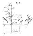
- Fig. 3 shows a first device for stripping of solar cells. Decoating takes place with a pulsed laser of the type Nd: YAG. Preferably, the laser resonator is operated with the method of quality modulation with pulse durations in the range of 25 ns.
- the processing beam is guided with the aid of a fiber optic cable 40 to an imaging optics with a focusing lens 34.
- the output 35 of the optical fiber 40 is imaged via the focusing lens 34 on the workpiece 31 in the processing area 41.
- the pulse energy density on the workpiece results in this structure from the pulse energy of the laser, the optical losses and the magnification of the optical system used.
- the necessary pulse energy density and the travel speed of the laser beam relative to the workpiece to be stripped at a given pulse frequency depend on the layer package to be removed.
- the tested laminates of thin film solar modules with pulse energy densities of the order of 1 J / cm 2 could be removed at traverse speeds of the order of 1 cm / s and a pulse frequency of 50 Hz.
- the workpiece 31 is held by a corresponding tool carrier 32, which may be, for example, a vacuum clamping table.
- the tool carrier 32 is in turn mounted on a CNC-controlled xy table 33.
- the table 33 with the tool carrier 32 and the workpiece 31 can be moved at a constant speed, so that the processing area 41 for stripping the solar cell 31 can be moved along a defined distance.
- Resulting vapors and dusts are extracted via suction devices 36, 38.
- nozzles 37, 39 are provided to protect the surface to be exposed from oxidation or other chemical processes with the atmosphere. Nitrogen has proved to be the most suitable protective gas here.
- the nozzles 37, 39 are adjusted so that in Processing area, the protective gas flows evenly over the surface of the workpiece.
- Optimum machining results are obtained when the optical axis 46 of the imaging optical unit is adjusted relative to the incidence slot 43 to an optimum machining angle to be determined for the respective application.
- tilt angles in the range of 5 ° -10 °, for example, have proven to be particularly favorable.
- Fig. 4 shows a second device for delamination of solar cells.
- the structure for mounting the solar cell 31 has been maintained compared to the first embodiment and is identified by the same reference numerals.
- a significant difference of the second device according to Fig. 4 to the first device is that the stripping according to Fig. 4 occurs in the region of the lower substrate layer.
- This application is used in all de-coating processes of solar cells, in which a transparent substrate is present and the substrate is to be completely exposed in certain areas. While fine hairline cracks in the decoating area resulted from an incidence from the layer side, the glass substrate could be decoated from the substrate side in the event of incidence of light, without it being possible to detect damage to the substrate in the light microscope.
- the optical structure otherwise resembles that in accordance with the first device, so that the processing beam with an optical waveguide 50 is likewise guided to imaging optics with a focusing lens 54.
- the focusing lens in turn forms the exit area 55 of the light guide 50 on the workpiece 31 in the processing area 51 from.
- the variant should be used with light from the substrate side.
- the methods according to the embodiments are combined in a suitable manner. For example, for the fracture sensitive edge regions of the substrate according to The second embodiment are stripped from the substrate side, since these edge regions are easily accessible for this case and thus corresponding cutouts in the tool carrier and in the clamping table are not needed.
- center regions to be stripped of special applications can again be stripped of the layer side.
Landscapes
- Engineering & Computer Science (AREA)
- Physics & Mathematics (AREA)
- Optics & Photonics (AREA)
- Plasma & Fusion (AREA)
- Mechanical Engineering (AREA)
- Laser Beam Processing (AREA)
- Photovoltaic Devices (AREA)
Applications Claiming Priority (7)
| Application Number | Priority Date | Filing Date | Title |
|---|---|---|---|
| DE19915640 | 1999-04-07 | ||
| DE19915640 | 1999-04-07 | ||
| DE19927529 | 1999-06-16 | ||
| DE19927529 | 1999-06-16 | ||
| DE19933703 | 1999-07-19 | ||
| DE19933703A DE19933703B4 (de) | 1999-04-07 | 1999-07-19 | Vorrichtung und Verfahren zum Abtragen von Schichten auf einer Solarzelle |
| PCT/EP2000/003132 WO2000060668A1 (de) | 1999-04-07 | 2000-04-07 | Vorrichtung und verfahren zum abtragen von dünnen schichten auf einem trägermaterial |
Publications (2)
| Publication Number | Publication Date |
|---|---|
| EP1166358A1 EP1166358A1 (de) | 2002-01-02 |
| EP1166358B1 true EP1166358B1 (de) | 2012-03-14 |
Family
ID=27219072
Family Applications (1)
| Application Number | Title | Priority Date | Filing Date |
|---|---|---|---|
| EP00925180A Expired - Lifetime EP1166358B1 (de) | 1999-04-07 | 2000-04-07 | Verfahren zum abtragen von dünnen schichten auf einem trägermaterial |
Country Status (6)
| Country | Link |
|---|---|
| US (1) | US6566628B2 (https=) |
| EP (1) | EP1166358B1 (https=) |
| JP (1) | JP5079942B2 (https=) |
| CN (1) | CN1211862C (https=) |
| AU (1) | AU4398700A (https=) |
| WO (1) | WO2000060668A1 (https=) |
Families Citing this family (41)
| Publication number | Priority date | Publication date | Assignee | Title |
|---|---|---|---|---|
| JP2004042140A (ja) * | 2002-07-12 | 2004-02-12 | Hitachi Zosen Corp | 薄膜除去方法及び装置 |
| NL1022231C2 (nl) * | 2002-12-20 | 2004-06-22 | Fico Bv | Werkwijze en inrichting voor het met een laserstraal bewerken van een drager voor ten minste één elektronische component. |
| KR20050094423A (ko) * | 2003-02-04 | 2005-09-27 | 아사히 가라스 가부시키가이샤 | 유리기판 표면의 이물 제거방법 |
| GB0412000D0 (en) * | 2004-05-28 | 2004-06-30 | Cambridge Display Tech Ltd | Apparatus and method for extracting debris during laser ablation |
| US7985942B2 (en) | 2004-05-28 | 2011-07-26 | Electro Scientific Industries, Inc. | Method of providing consistent quality of target material removal by lasers having different output performance characteristics |
| CN1981291B (zh) * | 2004-06-30 | 2011-06-15 | 通明国际科技有限公司 | 基于激光的用于处理目标表面材料的方法 |
| CN100591458C (zh) * | 2004-09-29 | 2010-02-24 | 三菱麻铁里亚尔株式会社 | 激光加工方法以及激光加工装置 |
| US20070107773A1 (en) | 2005-11-17 | 2007-05-17 | Palo Alto Research Center Incorporated | Bifacial cell with extruded gridline metallization |
| FR2893873B1 (fr) * | 2005-11-25 | 2008-12-12 | Air Liquide | Procede de coupage avec un laser a fibre d'acier inoxydable |
| US20070210420A1 (en) * | 2006-03-11 | 2007-09-13 | Nelson Curt L | Laser delamination of thin metal film using sacrificial polymer layer |
| US20070272666A1 (en) * | 2006-05-25 | 2007-11-29 | O'brien James N | Infrared laser wafer scribing using short pulses |
| US7928015B2 (en) | 2006-12-12 | 2011-04-19 | Palo Alto Research Center Incorporated | Solar cell fabrication using extruded dopant-bearing materials |
| DE102007015767A1 (de) * | 2007-03-30 | 2008-10-02 | Oerlikon Optics UK Ltd., Yarnton | Methode zum Laserritzen von Solarzellen |
| US7954449B2 (en) | 2007-05-08 | 2011-06-07 | Palo Alto Research Center Incorporated | Wiring-free, plumbing-free, cooled, vacuum chuck |
| EP3333280B1 (en) | 2007-09-12 | 2026-04-01 | Flisom AG | Method for manufacturing a compound film with compositional grading |
| DE102008015807A1 (de) * | 2008-03-27 | 2009-10-22 | Schott Solar Gmbh | Verfahren zur Strukturierung der Zinkoxid-Frontelektrodenschicht eines photovoltaischen Moduls |
| DE102008047675B4 (de) * | 2008-06-13 | 2014-05-15 | Ctf Solar Gmbh | Recycling-Verfahren für Dünnschichtsolarzellenmodule |
| US7999175B2 (en) | 2008-09-09 | 2011-08-16 | Palo Alto Research Center Incorporated | Interdigitated back contact silicon solar cells with laser ablated grooves |
| US9150966B2 (en) | 2008-11-14 | 2015-10-06 | Palo Alto Research Center Incorporated | Solar cell metallization using inline electroless plating |
| US20100190275A1 (en) * | 2009-01-29 | 2010-07-29 | Applied Materials, Inc. | Scribing device and method of producing a thin-film solar cell module |
| JP4472014B1 (ja) * | 2009-01-30 | 2010-06-02 | 株式会社 エスアンドデイ | 膜回収装置及び膜回収方法 |
| JP4773543B2 (ja) | 2009-04-17 | 2011-09-14 | 昭和シェル石油株式会社 | エッジスペースを備えた太陽電池モジュール |
| JP4773544B2 (ja) | 2009-04-17 | 2011-09-14 | 昭和シェル石油株式会社 | エッジスペースを備えた太陽電池モジュールの製造方法 |
| JP5340806B2 (ja) * | 2009-05-21 | 2013-11-13 | 株式会社ディスコ | 半導体ウエーハのレーザ加工方法 |
| JP5340807B2 (ja) * | 2009-05-21 | 2013-11-13 | 株式会社ディスコ | 半導体ウエーハの加工方法 |
| JP5582796B2 (ja) * | 2010-01-22 | 2014-09-03 | 日立造船株式会社 | レーザによる薄膜除去方法 |
| DE102010032958A1 (de) * | 2010-07-30 | 2012-02-02 | Messer Cutting & Welding Gmbh | Verfahren und Vorrichtung zum thermischen Bearbeiten eines Werkstücks mittels Laserstrahl |
| KR101282053B1 (ko) * | 2010-10-13 | 2013-07-04 | 한국표준과학연구원 | 레이저 다중 선로 공정에 의한 웨이퍼 미세 가공 방법 및 장치 |
| CN102110745B (zh) * | 2010-12-20 | 2012-07-04 | 东莞宏威薄膜真空技术有限公司 | 薄膜层边缘清除装置及清除方法 |
| US8962424B2 (en) | 2011-03-03 | 2015-02-24 | Palo Alto Research Center Incorporated | N-type silicon solar cell with contact/protection structures |
| US8461481B2 (en) * | 2011-04-19 | 2013-06-11 | Primestar Solar, Inc. | Methods and apparatus for reducing variations in the laser intensity during scribing a photovoltaic device |
| CN102759863B (zh) * | 2011-04-27 | 2015-12-02 | 瑞世达科技(厦门)有限公司 | 激光光刻机 |
| CN102692447B (zh) * | 2012-06-11 | 2014-04-02 | 燕山大学 | 小型化强脉冲单轨放电烧蚀装置 |
| US20160184926A1 (en) * | 2014-12-30 | 2016-06-30 | Suss Microtec Photonic Systems Inc. | Laser ablation system including variable energy beam to minimize etch-stop material damage |
| TW201700207A (zh) * | 2015-05-14 | 2017-01-01 | 應用材料股份有限公司 | 使用具低吸收特性之雷射波長來移除透明材料的方法 |
| US10547040B2 (en) | 2016-04-14 | 2020-01-28 | Applied Materials, Inc. | Energy storage device having an interlayer between electrode and electrolyte layer |
| EP3490011A1 (de) * | 2017-11-23 | 2019-05-29 | International Solar Energy Research Center Konstanz E.V. | Verfahren zur laserablation bei der herstellung von solarzellen |
| CN108913902A (zh) * | 2018-07-17 | 2018-11-30 | 成都中建材光电材料有限公司 | 一种薄膜太阳能电池组件的激光蒸发回收处理方法 |
| CN108807602A (zh) * | 2018-07-23 | 2018-11-13 | 北京铂阳顶荣光伏科技有限公司 | 一种薄膜太阳能基板电池材料的回收装置和回收方法 |
| CN112912923B (zh) * | 2018-10-23 | 2024-12-24 | 豪夫迈·罗氏有限公司 | 基于距离的组织状态确定 |
| WO2021237095A1 (en) * | 2020-05-22 | 2021-11-25 | Bold Laser Automation, Inc. | High velocity vacuum system for laser ablation |
Citations (2)
| Publication number | Priority date | Publication date | Assignee | Title |
|---|---|---|---|---|
| JPH09108880A (ja) * | 1995-10-23 | 1997-04-28 | Alps Electric Co Ltd | レーザ加工機 |
| WO1999003157A1 (en) * | 1997-07-11 | 1999-01-21 | Fed Corporation | Laser ablation method to fabricate color organic light emitting diode displays |
Family Cites Families (24)
| Publication number | Priority date | Publication date | Assignee | Title |
|---|---|---|---|---|
| US4650524A (en) * | 1984-06-20 | 1987-03-17 | Sanyo Electric Co., Ltd | Method for dividing semiconductor film formed on a substrate into plural regions by backside energy beam irradiation |
| JPS6240986A (ja) * | 1985-08-20 | 1987-02-21 | Fuji Electric Corp Res & Dev Ltd | レ−ザ−加工方法 |
| US4705698A (en) * | 1986-10-27 | 1987-11-10 | Chronar Corporation | Isolation of semiconductor contacts |
| DE3705500A1 (de) * | 1987-02-20 | 1988-09-01 | Siemens Ag | Verfahren zur strukturierung von solarzellen mit hilfe eines lasers im pulsbetrieb |
| DE3727825A1 (de) | 1987-08-20 | 1989-03-02 | Siemens Ag | Serienverschaltetes duennschichtsolarmodul aus kristallinem silizium |
| US4806728A (en) | 1988-02-01 | 1989-02-21 | Raytheon Company | Laser process apparatus |
| JPH0364043A (ja) * | 1989-08-01 | 1991-03-19 | Sanyo Electric Co Ltd | 太陽電池 |
| US5151135A (en) * | 1989-09-15 | 1992-09-29 | Amoco Corporation | Method for cleaning surfaces using UV lasers |
| EP0482240A1 (de) | 1990-10-24 | 1992-04-29 | Siemens Solar GmbH | Verfahren zur massgenauen Bearbeitung von flachen oder leicht gewölbten Werkstücken |
| DE59103714D1 (de) * | 1991-10-07 | 1995-01-12 | Siemens Ag | Laserbearbeitungsverfahren für einen Dünnschichtaufbau. |
| JP2750293B2 (ja) * | 1994-09-26 | 1998-05-13 | トヨタ自動車株式会社 | 成形品の製造方法及び成形品 |
| JP3293401B2 (ja) * | 1995-03-20 | 2002-06-17 | トヨタ自動車株式会社 | レーザ溶接方法 |
| JP3838580B2 (ja) * | 1995-09-30 | 2006-10-25 | 大日本印刷株式会社 | イージーオープン性を有する蓋材および該蓋材を用いた容器 |
| JPH09192875A (ja) * | 1996-01-10 | 1997-07-29 | Nikon Corp | レーザ加工装置 |
| JPH09248692A (ja) * | 1996-03-18 | 1997-09-22 | Hitachi Ltd | レーザマーク装置 |
| JP3309046B2 (ja) * | 1996-04-26 | 2002-07-29 | アルプス電気株式会社 | レーザ加工機 |
| US5741370A (en) * | 1996-06-27 | 1998-04-21 | Evergreen Solar, Inc. | Solar cell modules with improved backskin and methods for forming same |
| JP3305206B2 (ja) * | 1996-08-09 | 2002-07-22 | 三菱重工業株式会社 | レーザ加工装置 |
| JPH1099978A (ja) * | 1996-09-27 | 1998-04-21 | Hitachi Ltd | レーザー加工装置 |
| JP3436858B2 (ja) * | 1997-02-27 | 2003-08-18 | シャープ株式会社 | 薄膜太陽電池の製造方法 |
| JPH10305375A (ja) * | 1997-05-08 | 1998-11-17 | Sharp Corp | レーザ加工装置および方法 |
| US5818630A (en) * | 1997-06-25 | 1998-10-06 | Imra America, Inc. | Single-mode amplifiers and compressors based on multi-mode fibers |
| NL1006827C2 (nl) * | 1997-08-22 | 1999-02-23 | Free Energy Europ B V | Werkwijze voor het vervaardigen van zonnecellen, meer in het bijzonder dunne filmzonnecellen en zonnecellen verkregen volgens een dergelijke werkwijze. |
| JP3526224B2 (ja) * | 1998-10-20 | 2004-05-10 | シャープ株式会社 | 加工方法および光学部品 |
-
2000
- 2000-04-07 WO PCT/EP2000/003132 patent/WO2000060668A1/de not_active Ceased
- 2000-04-07 EP EP00925180A patent/EP1166358B1/de not_active Expired - Lifetime
- 2000-04-07 AU AU43987/00A patent/AU4398700A/en not_active Abandoned
- 2000-04-07 JP JP2000610068A patent/JP5079942B2/ja not_active Expired - Lifetime
- 2000-04-07 CN CNB008059772A patent/CN1211862C/zh not_active Expired - Lifetime
-
2001
- 2001-10-05 US US09/972,491 patent/US6566628B2/en not_active Expired - Lifetime
Patent Citations (2)
| Publication number | Priority date | Publication date | Assignee | Title |
|---|---|---|---|---|
| JPH09108880A (ja) * | 1995-10-23 | 1997-04-28 | Alps Electric Co Ltd | レーザ加工機 |
| WO1999003157A1 (en) * | 1997-07-11 | 1999-01-21 | Fed Corporation | Laser ablation method to fabricate color organic light emitting diode displays |
Also Published As
| Publication number | Publication date |
|---|---|
| JP2002540950A (ja) | 2002-12-03 |
| CN1211862C (zh) | 2005-07-20 |
| US6566628B2 (en) | 2003-05-20 |
| JP5079942B2 (ja) | 2012-11-21 |
| WO2000060668A1 (de) | 2000-10-12 |
| AU4398700A (en) | 2000-10-23 |
| CN1346517A (zh) | 2002-04-24 |
| US20020074318A1 (en) | 2002-06-20 |
| EP1166358A1 (de) | 2002-01-02 |
Similar Documents
| Publication | Publication Date | Title |
|---|---|---|
| EP1166358B1 (de) | Verfahren zum abtragen von dünnen schichten auf einem trägermaterial | |
| EP0536431B1 (de) | Laserbearbeitungsverfahren für einen Dünnschichtaufbau | |
| DE19933703B4 (de) | Vorrichtung und Verfahren zum Abtragen von Schichten auf einer Solarzelle | |
| DE60006127T2 (de) | Schaltungsvereinzelungssystem und verfahren | |
| DE69928488T2 (de) | Laserbearbeitung von einer Dünnschicht | |
| DE602004012999T2 (de) | Fokussierung eines optischen strahles auf zwei fokusse | |
| DE102014213775A1 (de) | Verfahren und Vorrichtung zum laserbasierten Bearbeiten von flächigen, kristallinen Substraten, insbesondere von Halbleitersubstraten | |
| WO2015132008A1 (de) | Verfahren zum schneiden einer laminierten, ultradünnen glasschicht | |
| EP1871566B1 (de) | Verfahren zum feinpolieren/-strukturieren wärmeempflindlicher dielektrischer materialien mittels laserstrahlung | |
| EP1747081A1 (de) | Verfahren und vorrichtung zum durchtrennen von halbleitermaterialien | |
| EP2083445A1 (de) | Verfahren zur Herstellung eines photovoltaischen Moduls | |
| DE102009021273A1 (de) | Verfahren und Vorrichtung zur Herstellung eines photovoltaischen Dünnschichtmoduls | |
| EP2520394B1 (de) | Vorrichtung und Verfahren zum Randentschichten und Kerben beschichteter Substrate mit zwei von der gleichen Seite auf das beschichtete transparente Substrat einwirkenden Laserquellen | |
| DE102011103481B4 (de) | Selektives Abtragen dünner Schichten mittels gepulster Laserstrahlung zur Dünnschichtstrukturierung | |
| DE3508469A1 (de) | Verfahren zum strukturieren von auf einem transparenten substrat aufgebrachten schichtfolgen | |
| DE10326505B4 (de) | Laserritzen von Dünnschichthalbleiterbauelementen | |
| DE102008038118A1 (de) | Verfahren und Anlagen zum Entschichten mit Laserstrahlen | |
| DE19964443B4 (de) | Vorrichtung zum Abtragen von Schichten auf einem Werkstück | |
| DE102009059193A1 (de) | Anlage und Verfahren zur Dotierung von Halbleitermaterialien | |
| DE19730028C2 (de) | Verfahren zum Trennen und Bearbeiten von auf einem Halbleitersubstrat im Verband hergestellten Halbleiterchips aus A III - B V- Verbindungshalbleitern unter Verwendung eines Excimer-Lasers | |
| EP2105241A2 (de) | Verfahren zur Strukturierung der Zinkoxid-Frontelektrodenschicht eines photovoltaischen Moduls | |
| DE102016210844A1 (de) | Vorrichtung und Verfahren zum Abtragen einer Schicht | |
| DE102012104230A1 (de) | Verfahren und Vorrichtung zum Einbringen von Strukturlinien in Dünnschicht-Photovoltaikmodule | |
| DE69503693T2 (de) | Verfahren zur Bearbeitung von oxidischen Materialien mittels eines Laserstrahls | |
| WO2010097064A2 (de) | Laserkristallisation durch bestrahlung |
Legal Events
| Date | Code | Title | Description |
|---|---|---|---|
| PUAI | Public reference made under article 153(3) epc to a published international application that has entered the european phase |
Free format text: ORIGINAL CODE: 0009012 |
|
| 17P | Request for examination filed |
Effective date: 20011017 |
|
| AK | Designated contracting states |
Kind code of ref document: A1 Designated state(s): AT BE CH CY DE DK ES FI FR GB GR IE IT LI LU MC NL PT SE |
|
| AX | Request for extension of the european patent |
Free format text: AL;LT;LV;MK;RO;SI |
|
| RAP1 | Party data changed (applicant data changed or rights of an application transferred) |
Owner name: SHELL SOLAR GMBH |
|
| RBV | Designated contracting states (corrected) |
Designated state(s): DE ES FI FR GB IT |
|
| RAP1 | Party data changed (applicant data changed or rights of an application transferred) |
Owner name: SHELL ERNEUERBARE ENERGIEN GMBH |
|
| 17Q | First examination report despatched |
Effective date: 20070823 |
|
| RAP1 | Party data changed (applicant data changed or rights of an application transferred) |
Owner name: SAINT-GOBAIN GLASS FRANCE S.A. |
|
| RTI1 | Title (correction) |
Free format text: METHOD FOR REMOVING THIN LAYERS ON A SUPPORT MATERIAL |
|
| GRAP | Despatch of communication of intention to grant a patent |
Free format text: ORIGINAL CODE: EPIDOSNIGR1 |
|
| GRAS | Grant fee paid |
Free format text: ORIGINAL CODE: EPIDOSNIGR3 |
|
| GRAA | (expected) grant |
Free format text: ORIGINAL CODE: 0009210 |
|
| AK | Designated contracting states |
Kind code of ref document: B1 Designated state(s): DE ES FI FR GB IT |
|
| REG | Reference to a national code |
Ref country code: GB Ref legal event code: FG4D Free format text: NOT ENGLISH |
|
| REG | Reference to a national code |
Ref country code: DE Ref legal event code: R096 Ref document number: 50016213 Country of ref document: DE Effective date: 20120516 |
|
| PLBE | No opposition filed within time limit |
Free format text: ORIGINAL CODE: 0009261 |
|
| STAA | Information on the status of an ep patent application or granted ep patent |
Free format text: STATUS: NO OPPOSITION FILED WITHIN TIME LIMIT |
|
| 26N | No opposition filed |
Effective date: 20121217 |
|
| REG | Reference to a national code |
Ref country code: DE Ref legal event code: R097 Ref document number: 50016213 Country of ref document: DE Effective date: 20121217 |
|
| PG25 | Lapsed in a contracting state [announced via postgrant information from national office to epo] |
Ref country code: ES Free format text: LAPSE BECAUSE OF FAILURE TO SUBMIT A TRANSLATION OF THE DESCRIPTION OR TO PAY THE FEE WITHIN THE PRESCRIBED TIME-LIMIT Effective date: 20120625 |
|
| PGFP | Annual fee paid to national office [announced via postgrant information from national office to epo] |
Ref country code: FI Payment date: 20150421 Year of fee payment: 16 |
|
| REG | Reference to a national code |
Ref country code: FR Ref legal event code: PLFP Year of fee payment: 17 |
|
| PG25 | Lapsed in a contracting state [announced via postgrant information from national office to epo] |
Ref country code: FI Free format text: LAPSE BECAUSE OF NON-PAYMENT OF DUE FEES Effective date: 20160407 |
|
| REG | Reference to a national code |
Ref country code: FR Ref legal event code: PLFP Year of fee payment: 18 |
|
| REG | Reference to a national code |
Ref country code: FR Ref legal event code: PLFP Year of fee payment: 19 |
|
| PGFP | Annual fee paid to national office [announced via postgrant information from national office to epo] |
Ref country code: IT Payment date: 20190419 Year of fee payment: 20 |
|
| PGFP | Annual fee paid to national office [announced via postgrant information from national office to epo] |
Ref country code: FR Payment date: 20190426 Year of fee payment: 20 |
|
| REG | Reference to a national code |
Ref country code: DE Ref legal event code: R082 Ref document number: 50016213 Country of ref document: DE Representative=s name: SPLANEMANN PATENTANWAELTE PARTNERSCHAFT MBB, DE Ref country code: DE Ref legal event code: R081 Ref document number: 50016213 Country of ref document: DE Owner name: (CNBM) BENGBU DESIGN & RESEARCH INSTITUTE FOR , CN Free format text: FORMER OWNER: SAINT-GOBAIN GLASS FRANCE S.A., COURBEVOIE, FR |
|
| PGFP | Annual fee paid to national office [announced via postgrant information from national office to epo] |
Ref country code: GB Payment date: 20190429 Year of fee payment: 20 Ref country code: DE Payment date: 20190628 Year of fee payment: 20 |
|
| REG | Reference to a national code |
Ref country code: GB Ref legal event code: 732E Free format text: REGISTERED BETWEEN 20191219 AND 20191224 |
|
| REG | Reference to a national code |
Ref country code: DE Ref legal event code: R071 Ref document number: 50016213 Country of ref document: DE |
|
| REG | Reference to a national code |
Ref country code: GB Ref legal event code: PE20 Expiry date: 20200406 |
|
| PG25 | Lapsed in a contracting state [announced via postgrant information from national office to epo] |
Ref country code: GB Free format text: LAPSE BECAUSE OF EXPIRATION OF PROTECTION Effective date: 20200406 |