EP1151892A2 - Fahrzeug mit einer Hochspannungsstromversorgung und Verfahren zum Starten eines solchen Fahrzeugs - Google Patents
Fahrzeug mit einer Hochspannungsstromversorgung und Verfahren zum Starten eines solchen Fahrzeugs Download PDFInfo
- Publication number
- EP1151892A2 EP1151892A2 EP01110393A EP01110393A EP1151892A2 EP 1151892 A2 EP1151892 A2 EP 1151892A2 EP 01110393 A EP01110393 A EP 01110393A EP 01110393 A EP01110393 A EP 01110393A EP 1151892 A2 EP1151892 A2 EP 1151892A2
- Authority
- EP
- European Patent Office
- Prior art keywords
- voltage
- battery
- low voltage
- power source
- vehicle
- Prior art date
- Legal status (The legal status is an assumption and is not a legal conclusion. Google has not performed a legal analysis and makes no representation as to the accuracy of the status listed.)
- Granted
Links
Images


Classifications
-
- B—PERFORMING OPERATIONS; TRANSPORTING
- B60—VEHICLES IN GENERAL
- B60L—PROPULSION OF ELECTRICALLY-PROPELLED VEHICLES; SUPPLYING ELECTRIC POWER FOR AUXILIARY EQUIPMENT OF ELECTRICALLY-PROPELLED VEHICLES; ELECTRODYNAMIC BRAKE SYSTEMS FOR VEHICLES IN GENERAL; MAGNETIC SUSPENSION OR LEVITATION FOR VEHICLES; MONITORING OPERATING VARIABLES OF ELECTRICALLY-PROPELLED VEHICLES; ELECTRIC SAFETY DEVICES FOR ELECTRICALLY-PROPELLED VEHICLES
- B60L58/00—Methods or circuit arrangements for monitoring or controlling batteries or fuel cells, specially adapted for electric vehicles
- B60L58/10—Methods or circuit arrangements for monitoring or controlling batteries or fuel cells, specially adapted for electric vehicles for monitoring or controlling batteries
- B60L58/12—Methods or circuit arrangements for monitoring or controlling batteries or fuel cells, specially adapted for electric vehicles for monitoring or controlling batteries responding to state of charge [SoC]
-
- B—PERFORMING OPERATIONS; TRANSPORTING
- B60—VEHICLES IN GENERAL
- B60K—ARRANGEMENT OR MOUNTING OF PROPULSION UNITS OR OF TRANSMISSIONS IN VEHICLES; ARRANGEMENT OR MOUNTING OF PLURAL DIVERSE PRIME-MOVERS IN VEHICLES; AUXILIARY DRIVES FOR VEHICLES; INSTRUMENTATION OR DASHBOARDS FOR VEHICLES; ARRANGEMENTS IN CONNECTION WITH COOLING, AIR INTAKE, GAS EXHAUST OR FUEL SUPPLY OF PROPULSION UNITS IN VEHICLES
- B60K6/00—Arrangement or mounting of plural diverse prime-movers for mutual or common propulsion, e.g. hybrid propulsion systems comprising electric motors and internal combustion engines ; Control systems therefor, i.e. systems controlling two or more prime movers, or controlling one of these prime movers and any of the transmission, drive or drive units Informative references: mechanical gearings with secondary electric drive F16H3/72; arrangements for handling mechanical energy structurally associated with the dynamo-electric machine H02K7/00; machines comprising structurally interrelated motor and generator parts H02K51/00; dynamo-electric machines not otherwise provided for in H02K see H02K99/00
- B60K6/20—Arrangement or mounting of plural diverse prime-movers for mutual or common propulsion, e.g. hybrid propulsion systems comprising electric motors and internal combustion engines ; Control systems therefor, i.e. systems controlling two or more prime movers, or controlling one of these prime movers and any of the transmission, drive or drive units Informative references: mechanical gearings with secondary electric drive F16H3/72; arrangements for handling mechanical energy structurally associated with the dynamo-electric machine H02K7/00; machines comprising structurally interrelated motor and generator parts H02K51/00; dynamo-electric machines not otherwise provided for in H02K see H02K99/00 the prime-movers consisting of electric motors and internal combustion engines, e.g. HEVs
- B60K6/42—Arrangement or mounting of plural diverse prime-movers for mutual or common propulsion, e.g. hybrid propulsion systems comprising electric motors and internal combustion engines ; Control systems therefor, i.e. systems controlling two or more prime movers, or controlling one of these prime movers and any of the transmission, drive or drive units Informative references: mechanical gearings with secondary electric drive F16H3/72; arrangements for handling mechanical energy structurally associated with the dynamo-electric machine H02K7/00; machines comprising structurally interrelated motor and generator parts H02K51/00; dynamo-electric machines not otherwise provided for in H02K see H02K99/00 the prime-movers consisting of electric motors and internal combustion engines, e.g. HEVs characterised by the architecture of the hybrid electric vehicle
- B60K6/44—Series-parallel type
- B60K6/445—Differential gearing distribution type
-
- B—PERFORMING OPERATIONS; TRANSPORTING
- B60—VEHICLES IN GENERAL
- B60L—PROPULSION OF ELECTRICALLY-PROPELLED VEHICLES; SUPPLYING ELECTRIC POWER FOR AUXILIARY EQUIPMENT OF ELECTRICALLY-PROPELLED VEHICLES; ELECTRODYNAMIC BRAKE SYSTEMS FOR VEHICLES IN GENERAL; MAGNETIC SUSPENSION OR LEVITATION FOR VEHICLES; MONITORING OPERATING VARIABLES OF ELECTRICALLY-PROPELLED VEHICLES; ELECTRIC SAFETY DEVICES FOR ELECTRICALLY-PROPELLED VEHICLES
- B60L3/00—Electric devices on electrically-propelled vehicles for safety purposes; Monitoring operating variables, e.g. speed, deceleration or energy consumption
- B60L3/0023—Detecting, eliminating, remedying or compensating for drive train abnormalities, e.g. failures within the drive train
- B60L3/0053—Detecting, eliminating, remedying or compensating for drive train abnormalities, e.g. failures within the drive train relating to fuel cells
-
- B—PERFORMING OPERATIONS; TRANSPORTING
- B60—VEHICLES IN GENERAL
- B60L—PROPULSION OF ELECTRICALLY-PROPELLED VEHICLES; SUPPLYING ELECTRIC POWER FOR AUXILIARY EQUIPMENT OF ELECTRICALLY-PROPELLED VEHICLES; ELECTRODYNAMIC BRAKE SYSTEMS FOR VEHICLES IN GENERAL; MAGNETIC SUSPENSION OR LEVITATION FOR VEHICLES; MONITORING OPERATING VARIABLES OF ELECTRICALLY-PROPELLED VEHICLES; ELECTRIC SAFETY DEVICES FOR ELECTRICALLY-PROPELLED VEHICLES
- B60L3/00—Electric devices on electrically-propelled vehicles for safety purposes; Monitoring operating variables, e.g. speed, deceleration or energy consumption
- B60L3/0023—Detecting, eliminating, remedying or compensating for drive train abnormalities, e.g. failures within the drive train
- B60L3/0084—Detecting, eliminating, remedying or compensating for drive train abnormalities, e.g. failures within the drive train relating to control modules
-
- B—PERFORMING OPERATIONS; TRANSPORTING
- B60—VEHICLES IN GENERAL
- B60L—PROPULSION OF ELECTRICALLY-PROPELLED VEHICLES; SUPPLYING ELECTRIC POWER FOR AUXILIARY EQUIPMENT OF ELECTRICALLY-PROPELLED VEHICLES; ELECTRODYNAMIC BRAKE SYSTEMS FOR VEHICLES IN GENERAL; MAGNETIC SUSPENSION OR LEVITATION FOR VEHICLES; MONITORING OPERATING VARIABLES OF ELECTRICALLY-PROPELLED VEHICLES; ELECTRIC SAFETY DEVICES FOR ELECTRICALLY-PROPELLED VEHICLES
- B60L3/00—Electric devices on electrically-propelled vehicles for safety purposes; Monitoring operating variables, e.g. speed, deceleration or energy consumption
- B60L3/04—Cutting off the power supply under fault conditions
-
- B—PERFORMING OPERATIONS; TRANSPORTING
- B60—VEHICLES IN GENERAL
- B60L—PROPULSION OF ELECTRICALLY-PROPELLED VEHICLES; SUPPLYING ELECTRIC POWER FOR AUXILIARY EQUIPMENT OF ELECTRICALLY-PROPELLED VEHICLES; ELECTRODYNAMIC BRAKE SYSTEMS FOR VEHICLES IN GENERAL; MAGNETIC SUSPENSION OR LEVITATION FOR VEHICLES; MONITORING OPERATING VARIABLES OF ELECTRICALLY-PROPELLED VEHICLES; ELECTRIC SAFETY DEVICES FOR ELECTRICALLY-PROPELLED VEHICLES
- B60L3/00—Electric devices on electrically-propelled vehicles for safety purposes; Monitoring operating variables, e.g. speed, deceleration or energy consumption
- B60L3/12—Recording operating variables ; Monitoring of operating variables
-
- B—PERFORMING OPERATIONS; TRANSPORTING
- B60—VEHICLES IN GENERAL
- B60L—PROPULSION OF ELECTRICALLY-PROPELLED VEHICLES; SUPPLYING ELECTRIC POWER FOR AUXILIARY EQUIPMENT OF ELECTRICALLY-PROPELLED VEHICLES; ELECTRODYNAMIC BRAKE SYSTEMS FOR VEHICLES IN GENERAL; MAGNETIC SUSPENSION OR LEVITATION FOR VEHICLES; MONITORING OPERATING VARIABLES OF ELECTRICALLY-PROPELLED VEHICLES; ELECTRIC SAFETY DEVICES FOR ELECTRICALLY-PROPELLED VEHICLES
- B60L50/00—Electric propulsion with power supplied within the vehicle
- B60L50/10—Electric propulsion with power supplied within the vehicle using propulsion power supplied by engine-driven generators, e.g. generators driven by combustion engines
- B60L50/16—Electric propulsion with power supplied within the vehicle using propulsion power supplied by engine-driven generators, e.g. generators driven by combustion engines with provision for separate direct mechanical propulsion
-
- B—PERFORMING OPERATIONS; TRANSPORTING
- B60—VEHICLES IN GENERAL
- B60L—PROPULSION OF ELECTRICALLY-PROPELLED VEHICLES; SUPPLYING ELECTRIC POWER FOR AUXILIARY EQUIPMENT OF ELECTRICALLY-PROPELLED VEHICLES; ELECTRODYNAMIC BRAKE SYSTEMS FOR VEHICLES IN GENERAL; MAGNETIC SUSPENSION OR LEVITATION FOR VEHICLES; MONITORING OPERATING VARIABLES OF ELECTRICALLY-PROPELLED VEHICLES; ELECTRIC SAFETY DEVICES FOR ELECTRICALLY-PROPELLED VEHICLES
- B60L50/00—Electric propulsion with power supplied within the vehicle
- B60L50/50—Electric propulsion with power supplied within the vehicle using propulsion power supplied by batteries or fuel cells
- B60L50/60—Electric propulsion with power supplied within the vehicle using propulsion power supplied by batteries or fuel cells using power supplied by batteries
- B60L50/61—Electric propulsion with power supplied within the vehicle using propulsion power supplied by batteries or fuel cells using power supplied by batteries by batteries charged by engine-driven generators, e.g. series hybrid electric vehicles
-
- B—PERFORMING OPERATIONS; TRANSPORTING
- B60—VEHICLES IN GENERAL
- B60L—PROPULSION OF ELECTRICALLY-PROPELLED VEHICLES; SUPPLYING ELECTRIC POWER FOR AUXILIARY EQUIPMENT OF ELECTRICALLY-PROPELLED VEHICLES; ELECTRODYNAMIC BRAKE SYSTEMS FOR VEHICLES IN GENERAL; MAGNETIC SUSPENSION OR LEVITATION FOR VEHICLES; MONITORING OPERATING VARIABLES OF ELECTRICALLY-PROPELLED VEHICLES; ELECTRIC SAFETY DEVICES FOR ELECTRICALLY-PROPELLED VEHICLES
- B60L58/00—Methods or circuit arrangements for monitoring or controlling batteries or fuel cells, specially adapted for electric vehicles
- B60L58/10—Methods or circuit arrangements for monitoring or controlling batteries or fuel cells, specially adapted for electric vehicles for monitoring or controlling batteries
- B60L58/18—Methods or circuit arrangements for monitoring or controlling batteries or fuel cells, specially adapted for electric vehicles for monitoring or controlling batteries of two or more battery modules
- B60L58/20—Methods or circuit arrangements for monitoring or controlling batteries or fuel cells, specially adapted for electric vehicles for monitoring or controlling batteries of two or more battery modules having different nominal voltages
-
- B—PERFORMING OPERATIONS; TRANSPORTING
- B60—VEHICLES IN GENERAL
- B60L—PROPULSION OF ELECTRICALLY-PROPELLED VEHICLES; SUPPLYING ELECTRIC POWER FOR AUXILIARY EQUIPMENT OF ELECTRICALLY-PROPELLED VEHICLES; ELECTRODYNAMIC BRAKE SYSTEMS FOR VEHICLES IN GENERAL; MAGNETIC SUSPENSION OR LEVITATION FOR VEHICLES; MONITORING OPERATING VARIABLES OF ELECTRICALLY-PROPELLED VEHICLES; ELECTRIC SAFETY DEVICES FOR ELECTRICALLY-PROPELLED VEHICLES
- B60L7/00—Electrodynamic brake systems for vehicles in general
- B60L7/10—Dynamic electric regenerative braking
- B60L7/14—Dynamic electric regenerative braking for vehicles propelled by ac motors
-
- B—PERFORMING OPERATIONS; TRANSPORTING
- B60—VEHICLES IN GENERAL
- B60W—CONJOINT CONTROL OF VEHICLE SUB-UNITS OF DIFFERENT TYPE OR DIFFERENT FUNCTION; CONTROL SYSTEMS SPECIALLY ADAPTED FOR HYBRID VEHICLES; ROAD VEHICLE DRIVE CONTROL SYSTEMS FOR PURPOSES NOT RELATED TO THE CONTROL OF A PARTICULAR SUB-UNIT
- B60W10/00—Conjoint control of vehicle sub-units of different type or different function
- B60W10/04—Conjoint control of vehicle sub-units of different type or different function including control of propulsion units
- B60W10/08—Conjoint control of vehicle sub-units of different type or different function including control of propulsion units including control of electric propulsion units, e.g. motors or generators
-
- B—PERFORMING OPERATIONS; TRANSPORTING
- B60—VEHICLES IN GENERAL
- B60W—CONJOINT CONTROL OF VEHICLE SUB-UNITS OF DIFFERENT TYPE OR DIFFERENT FUNCTION; CONTROL SYSTEMS SPECIALLY ADAPTED FOR HYBRID VEHICLES; ROAD VEHICLE DRIVE CONTROL SYSTEMS FOR PURPOSES NOT RELATED TO THE CONTROL OF A PARTICULAR SUB-UNIT
- B60W10/00—Conjoint control of vehicle sub-units of different type or different function
- B60W10/24—Conjoint control of vehicle sub-units of different type or different function including control of energy storage means
- B60W10/26—Conjoint control of vehicle sub-units of different type or different function including control of energy storage means for electrical energy, e.g. batteries or capacitors
-
- B—PERFORMING OPERATIONS; TRANSPORTING
- B60—VEHICLES IN GENERAL
- B60W—CONJOINT CONTROL OF VEHICLE SUB-UNITS OF DIFFERENT TYPE OR DIFFERENT FUNCTION; CONTROL SYSTEMS SPECIALLY ADAPTED FOR HYBRID VEHICLES; ROAD VEHICLE DRIVE CONTROL SYSTEMS FOR PURPOSES NOT RELATED TO THE CONTROL OF A PARTICULAR SUB-UNIT
- B60W10/00—Conjoint control of vehicle sub-units of different type or different function
- B60W10/30—Conjoint control of vehicle sub-units of different type or different function including control of auxiliary equipment, e.g. air-conditioning compressors or oil pumps
-
- B—PERFORMING OPERATIONS; TRANSPORTING
- B60—VEHICLES IN GENERAL
- B60W—CONJOINT CONTROL OF VEHICLE SUB-UNITS OF DIFFERENT TYPE OR DIFFERENT FUNCTION; CONTROL SYSTEMS SPECIALLY ADAPTED FOR HYBRID VEHICLES; ROAD VEHICLE DRIVE CONTROL SYSTEMS FOR PURPOSES NOT RELATED TO THE CONTROL OF A PARTICULAR SUB-UNIT
- B60W20/00—Control systems specially adapted for hybrid vehicles
- B60W20/10—Controlling the power contribution of each of the prime movers to meet required power demand
-
- B—PERFORMING OPERATIONS; TRANSPORTING
- B60—VEHICLES IN GENERAL
- B60L—PROPULSION OF ELECTRICALLY-PROPELLED VEHICLES; SUPPLYING ELECTRIC POWER FOR AUXILIARY EQUIPMENT OF ELECTRICALLY-PROPELLED VEHICLES; ELECTRODYNAMIC BRAKE SYSTEMS FOR VEHICLES IN GENERAL; MAGNETIC SUSPENSION OR LEVITATION FOR VEHICLES; MONITORING OPERATING VARIABLES OF ELECTRICALLY-PROPELLED VEHICLES; ELECTRIC SAFETY DEVICES FOR ELECTRICALLY-PROPELLED VEHICLES
- B60L2210/00—Converter types
- B60L2210/10—DC to DC converters
- B60L2210/12—Buck converters
-
- B—PERFORMING OPERATIONS; TRANSPORTING
- B60—VEHICLES IN GENERAL
- B60L—PROPULSION OF ELECTRICALLY-PROPELLED VEHICLES; SUPPLYING ELECTRIC POWER FOR AUXILIARY EQUIPMENT OF ELECTRICALLY-PROPELLED VEHICLES; ELECTRODYNAMIC BRAKE SYSTEMS FOR VEHICLES IN GENERAL; MAGNETIC SUSPENSION OR LEVITATION FOR VEHICLES; MONITORING OPERATING VARIABLES OF ELECTRICALLY-PROPELLED VEHICLES; ELECTRIC SAFETY DEVICES FOR ELECTRICALLY-PROPELLED VEHICLES
- B60L2210/00—Converter types
- B60L2210/40—DC to AC converters
-
- B—PERFORMING OPERATIONS; TRANSPORTING
- B60—VEHICLES IN GENERAL
- B60L—PROPULSION OF ELECTRICALLY-PROPELLED VEHICLES; SUPPLYING ELECTRIC POWER FOR AUXILIARY EQUIPMENT OF ELECTRICALLY-PROPELLED VEHICLES; ELECTRODYNAMIC BRAKE SYSTEMS FOR VEHICLES IN GENERAL; MAGNETIC SUSPENSION OR LEVITATION FOR VEHICLES; MONITORING OPERATING VARIABLES OF ELECTRICALLY-PROPELLED VEHICLES; ELECTRIC SAFETY DEVICES FOR ELECTRICALLY-PROPELLED VEHICLES
- B60L2220/00—Electrical machine types; Structures or applications thereof
- B60L2220/10—Electrical machine types
- B60L2220/14—Synchronous machines
-
- B—PERFORMING OPERATIONS; TRANSPORTING
- B60—VEHICLES IN GENERAL
- B60L—PROPULSION OF ELECTRICALLY-PROPELLED VEHICLES; SUPPLYING ELECTRIC POWER FOR AUXILIARY EQUIPMENT OF ELECTRICALLY-PROPELLED VEHICLES; ELECTRODYNAMIC BRAKE SYSTEMS FOR VEHICLES IN GENERAL; MAGNETIC SUSPENSION OR LEVITATION FOR VEHICLES; MONITORING OPERATING VARIABLES OF ELECTRICALLY-PROPELLED VEHICLES; ELECTRIC SAFETY DEVICES FOR ELECTRICALLY-PROPELLED VEHICLES
- B60L2240/00—Control parameters of input or output; Target parameters
- B60L2240/40—Drive Train control parameters
- B60L2240/42—Drive Train control parameters related to electric machines
- B60L2240/421—Speed
-
- B—PERFORMING OPERATIONS; TRANSPORTING
- B60—VEHICLES IN GENERAL
- B60L—PROPULSION OF ELECTRICALLY-PROPELLED VEHICLES; SUPPLYING ELECTRIC POWER FOR AUXILIARY EQUIPMENT OF ELECTRICALLY-PROPELLED VEHICLES; ELECTRODYNAMIC BRAKE SYSTEMS FOR VEHICLES IN GENERAL; MAGNETIC SUSPENSION OR LEVITATION FOR VEHICLES; MONITORING OPERATING VARIABLES OF ELECTRICALLY-PROPELLED VEHICLES; ELECTRIC SAFETY DEVICES FOR ELECTRICALLY-PROPELLED VEHICLES
- B60L2240/00—Control parameters of input or output; Target parameters
- B60L2240/40—Drive Train control parameters
- B60L2240/44—Drive Train control parameters related to combustion engines
- B60L2240/443—Torque
-
- B—PERFORMING OPERATIONS; TRANSPORTING
- B60—VEHICLES IN GENERAL
- B60L—PROPULSION OF ELECTRICALLY-PROPELLED VEHICLES; SUPPLYING ELECTRIC POWER FOR AUXILIARY EQUIPMENT OF ELECTRICALLY-PROPELLED VEHICLES; ELECTRODYNAMIC BRAKE SYSTEMS FOR VEHICLES IN GENERAL; MAGNETIC SUSPENSION OR LEVITATION FOR VEHICLES; MONITORING OPERATING VARIABLES OF ELECTRICALLY-PROPELLED VEHICLES; ELECTRIC SAFETY DEVICES FOR ELECTRICALLY-PROPELLED VEHICLES
- B60L2250/00—Driver interactions
- B60L2250/10—Driver interactions by alarm
-
- B—PERFORMING OPERATIONS; TRANSPORTING
- B60—VEHICLES IN GENERAL
- B60L—PROPULSION OF ELECTRICALLY-PROPELLED VEHICLES; SUPPLYING ELECTRIC POWER FOR AUXILIARY EQUIPMENT OF ELECTRICALLY-PROPELLED VEHICLES; ELECTRODYNAMIC BRAKE SYSTEMS FOR VEHICLES IN GENERAL; MAGNETIC SUSPENSION OR LEVITATION FOR VEHICLES; MONITORING OPERATING VARIABLES OF ELECTRICALLY-PROPELLED VEHICLES; ELECTRIC SAFETY DEVICES FOR ELECTRICALLY-PROPELLED VEHICLES
- B60L2250/00—Driver interactions
- B60L2250/16—Driver interactions by display
-
- B—PERFORMING OPERATIONS; TRANSPORTING
- B60—VEHICLES IN GENERAL
- B60W—CONJOINT CONTROL OF VEHICLE SUB-UNITS OF DIFFERENT TYPE OR DIFFERENT FUNCTION; CONTROL SYSTEMS SPECIALLY ADAPTED FOR HYBRID VEHICLES; ROAD VEHICLE DRIVE CONTROL SYSTEMS FOR PURPOSES NOT RELATED TO THE CONTROL OF A PARTICULAR SUB-UNIT
- B60W20/00—Control systems specially adapted for hybrid vehicles
-
- B—PERFORMING OPERATIONS; TRANSPORTING
- B60—VEHICLES IN GENERAL
- B60W—CONJOINT CONTROL OF VEHICLE SUB-UNITS OF DIFFERENT TYPE OR DIFFERENT FUNCTION; CONTROL SYSTEMS SPECIALLY ADAPTED FOR HYBRID VEHICLES; ROAD VEHICLE DRIVE CONTROL SYSTEMS FOR PURPOSES NOT RELATED TO THE CONTROL OF A PARTICULAR SUB-UNIT
- B60W2510/00—Input parameters relating to a particular sub-units
- B60W2510/24—Energy storage means
- B60W2510/242—Energy storage means for electrical energy
- B60W2510/244—Charge state
-
- Y—GENERAL TAGGING OF NEW TECHNOLOGICAL DEVELOPMENTS; GENERAL TAGGING OF CROSS-SECTIONAL TECHNOLOGIES SPANNING OVER SEVERAL SECTIONS OF THE IPC; TECHNICAL SUBJECTS COVERED BY FORMER USPC CROSS-REFERENCE ART COLLECTIONS [XRACs] AND DIGESTS
- Y02—TECHNOLOGIES OR APPLICATIONS FOR MITIGATION OR ADAPTATION AGAINST CLIMATE CHANGE
- Y02T—CLIMATE CHANGE MITIGATION TECHNOLOGIES RELATED TO TRANSPORTATION
- Y02T10/00—Road transport of goods or passengers
- Y02T10/60—Other road transportation technologies with climate change mitigation effect
- Y02T10/62—Hybrid vehicles
-
- Y—GENERAL TAGGING OF NEW TECHNOLOGICAL DEVELOPMENTS; GENERAL TAGGING OF CROSS-SECTIONAL TECHNOLOGIES SPANNING OVER SEVERAL SECTIONS OF THE IPC; TECHNICAL SUBJECTS COVERED BY FORMER USPC CROSS-REFERENCE ART COLLECTIONS [XRACs] AND DIGESTS
- Y02—TECHNOLOGIES OR APPLICATIONS FOR MITIGATION OR ADAPTATION AGAINST CLIMATE CHANGE
- Y02T—CLIMATE CHANGE MITIGATION TECHNOLOGIES RELATED TO TRANSPORTATION
- Y02T10/00—Road transport of goods or passengers
- Y02T10/60—Other road transportation technologies with climate change mitigation effect
- Y02T10/64—Electric machine technologies in electromobility
-
- Y—GENERAL TAGGING OF NEW TECHNOLOGICAL DEVELOPMENTS; GENERAL TAGGING OF CROSS-SECTIONAL TECHNOLOGIES SPANNING OVER SEVERAL SECTIONS OF THE IPC; TECHNICAL SUBJECTS COVERED BY FORMER USPC CROSS-REFERENCE ART COLLECTIONS [XRACs] AND DIGESTS
- Y02—TECHNOLOGIES OR APPLICATIONS FOR MITIGATION OR ADAPTATION AGAINST CLIMATE CHANGE
- Y02T—CLIMATE CHANGE MITIGATION TECHNOLOGIES RELATED TO TRANSPORTATION
- Y02T10/00—Road transport of goods or passengers
- Y02T10/60—Other road transportation technologies with climate change mitigation effect
- Y02T10/70—Energy storage systems for electromobility, e.g. batteries
-
- Y—GENERAL TAGGING OF NEW TECHNOLOGICAL DEVELOPMENTS; GENERAL TAGGING OF CROSS-SECTIONAL TECHNOLOGIES SPANNING OVER SEVERAL SECTIONS OF THE IPC; TECHNICAL SUBJECTS COVERED BY FORMER USPC CROSS-REFERENCE ART COLLECTIONS [XRACs] AND DIGESTS
- Y02—TECHNOLOGIES OR APPLICATIONS FOR MITIGATION OR ADAPTATION AGAINST CLIMATE CHANGE
- Y02T—CLIMATE CHANGE MITIGATION TECHNOLOGIES RELATED TO TRANSPORTATION
- Y02T10/00—Road transport of goods or passengers
- Y02T10/60—Other road transportation technologies with climate change mitigation effect
- Y02T10/7072—Electromobility specific charging systems or methods for batteries, ultracapacitors, supercapacitors or double-layer capacitors
-
- Y—GENERAL TAGGING OF NEW TECHNOLOGICAL DEVELOPMENTS; GENERAL TAGGING OF CROSS-SECTIONAL TECHNOLOGIES SPANNING OVER SEVERAL SECTIONS OF THE IPC; TECHNICAL SUBJECTS COVERED BY FORMER USPC CROSS-REFERENCE ART COLLECTIONS [XRACs] AND DIGESTS
- Y02—TECHNOLOGIES OR APPLICATIONS FOR MITIGATION OR ADAPTATION AGAINST CLIMATE CHANGE
- Y02T—CLIMATE CHANGE MITIGATION TECHNOLOGIES RELATED TO TRANSPORTATION
- Y02T10/00—Road transport of goods or passengers
- Y02T10/60—Other road transportation technologies with climate change mitigation effect
- Y02T10/72—Electric energy management in electromobility
-
- Y—GENERAL TAGGING OF NEW TECHNOLOGICAL DEVELOPMENTS; GENERAL TAGGING OF CROSS-SECTIONAL TECHNOLOGIES SPANNING OVER SEVERAL SECTIONS OF THE IPC; TECHNICAL SUBJECTS COVERED BY FORMER USPC CROSS-REFERENCE ART COLLECTIONS [XRACs] AND DIGESTS
- Y02—TECHNOLOGIES OR APPLICATIONS FOR MITIGATION OR ADAPTATION AGAINST CLIMATE CHANGE
- Y02T—CLIMATE CHANGE MITIGATION TECHNOLOGIES RELATED TO TRANSPORTATION
- Y02T10/00—Road transport of goods or passengers
- Y02T10/80—Technologies aiming to reduce greenhouse gasses emissions common to all road transportation technologies
- Y02T10/92—Energy efficient charging or discharging systems for batteries, ultracapacitors, supercapacitors or double-layer capacitors specially adapted for vehicles
-
- Y—GENERAL TAGGING OF NEW TECHNOLOGICAL DEVELOPMENTS; GENERAL TAGGING OF CROSS-SECTIONAL TECHNOLOGIES SPANNING OVER SEVERAL SECTIONS OF THE IPC; TECHNICAL SUBJECTS COVERED BY FORMER USPC CROSS-REFERENCE ART COLLECTIONS [XRACs] AND DIGESTS
- Y02—TECHNOLOGIES OR APPLICATIONS FOR MITIGATION OR ADAPTATION AGAINST CLIMATE CHANGE
- Y02T—CLIMATE CHANGE MITIGATION TECHNOLOGIES RELATED TO TRANSPORTATION
- Y02T90/00—Enabling technologies or technologies with a potential or indirect contribution to GHG emissions mitigation
- Y02T90/40—Application of hydrogen technology to transportation, e.g. using fuel cells
-
- Y—GENERAL TAGGING OF NEW TECHNOLOGICAL DEVELOPMENTS; GENERAL TAGGING OF CROSS-SECTIONAL TECHNOLOGIES SPANNING OVER SEVERAL SECTIONS OF THE IPC; TECHNICAL SUBJECTS COVERED BY FORMER USPC CROSS-REFERENCE ART COLLECTIONS [XRACs] AND DIGESTS
- Y10—TECHNICAL SUBJECTS COVERED BY FORMER USPC
- Y10S—TECHNICAL SUBJECTS COVERED BY FORMER USPC CROSS-REFERENCE ART COLLECTIONS [XRACs] AND DIGESTS
- Y10S903/00—Hybrid electric vehicles, HEVS
- Y10S903/902—Prime movers comprising electrical and internal combustion motors
- Y10S903/903—Prime movers comprising electrical and internal combustion motors having energy storing means, e.g. battery, capacitor
Definitions
- the present invention relates to a vehicle that utilizes electrical energy of a high voltage power source system, a power source system controller mounted on an apparatus that utilizes the electrical energy of the high voltage power source system, and a method of controlling a power source system. More specifically the invention pertains to a technique that utilizes a converter to convert the electrical energy of a high voltage battery into a low voltage and supply the converted low voltage and accordingly enables application of the electrical energy of a high voltage power source system including the high voltage battery.
- Typical examples of such vehicles include special vehicles that have a high voltage battery mounted thereon and carry out various works with the electric power of the high voltage battery, electric vehicles that run with the energy of a battery, and hybrid vehicles that have an internal combustion engine and a battery mounted thereon and use the power of the internal combustion engine in combination with the power of the battery.
- These vehicles generally have two batteries, that is, a high voltage battery that stores high voltage electrical energy used for driving and a low voltage battery that stores low voltage electrical energy used for controlling drives of the vehicle and regulating auxiliary machinery mounted on the vehicle.
- the low voltage battery While the low voltage battery is used only as the auxiliary machinery battery in conventional vehicles driven with only the power of the internal combustion engine, the low voltage battery functions as the power source for controlling a high voltage power source system including the high voltage battery in addition to the function as the auxiliary machinery battery in these recently proposed vehicles. Namely the low voltage battery is of the greater importance with an increase of its loading.
- the prior art electric vehicle In order to ensure supply of electrical energy to the low voltage battery, the prior art electric vehicle has a converter circuit that converts the electrical energy of the high voltage power source system into a low voltage and charges the low voltage battery with the converted low voltage electrical energy.
- the voltage drop of the low voltage battery is inevitable, due to the continuously driven, large electric loading like headlights and the natural discharge from the battery in the inactive state over a long term.
- the proposed safety measures by taking into account the importance of the low voltage battery inhibit the system of the electric vehicle from being activated when the voltage of the low voltage battery is lower than a minimum reference voltage. While the voltage of the low voltage battery is lower than a predetermined level, the voltage of the power line for a controller that takes charge of control operations may fluctuated even with the use of a stabilizing power source unit.
- the prior art vehicle and the prior art power source controller mounted on an apparatus thus uniformly inhibit its activation when the voltage of the lower voltage battery is lower than the predetermined level.
- the method of uniformly inhibiting the activation undesirably lowers the convenience in use of the prior art vehicle and the prior art power source controller mounted on the apparatus.
- the loading applied to the low voltage battery has been increasing significantly.
- a simple increase in storage capacity with the increasing load has limitations, since it undesirably makes the low voltage battery bulky and heavy.
- the voltage of the low voltage battery that is subject to heavy loading may thus be deviated from a normal range and lowered to or below the minimum reference voltage.
- the prior art technique inhibits the power supply to the controller that takes charge of control operations relating to drives of the vehicle, thus prohibiting the vehicle from being activated.
- a simple decrease in minimum reference voltage undesirably lowers the safety factor of the whole system and is thus not adoptable.
- the low voltage battery is also generally used as the power source for driving an apparatus that establishes the high voltage power source line, for example, a relay that connects the output of the high voltage battery with the power line of the high voltage power source system.
- a relay that connects the output of the high voltage battery with the power line of the high voltage power source system.
- the extreme drop in voltage of the low voltage battery makes the operations of such an apparatus unstable. Under the condition of the lowered voltage of the low voltage power source system, the contact of the relay that switches on and off the high voltage has weak working force. This may result in welding the contact. It is thus impractical to simply decrease the lower limit voltage of the low voltage battery that allows a start of the vehicle or the apparatus.
- the object of the present invention is thus to provide a technique that brings out the best performance of a low voltage battery, while ensuring safety of a whole system.
- the technique allows a start of the vehicle while guaranteeing the normal operation of the whole system of the vehicle.
- a vehicle that utilizes electrical energy of a high voltage power source system including a high voltage battery.
- the vehicle includes: a control unit that carries out controls related to driving of the vehicle; a low voltage power source circuit that supplies electrical energy of a low voltage power source system including a low voltage battery to the control unit; a battery voltage measurement unit that measures a voltage level of the low voltage battery; a converter unit that converts the electrical energy of the high voltage power source system into a low voltage and charges the low voltage battery with the converted low voltage electrical energy; and a recovery unit that, when the observed voltage of the low voltage battery is lower than a preset minimum reference voltage at the time of a requirement to start the vehicle, activates the converter unit to recover the voltage of the low voltage battery to the preset minimum reference voltage, prior to a permission to operate the control unit.
- the converter unit in response to a requirement to start the vehicle, the converter unit converts the voltage of the high voltage battery into a low voltage, charges the low voltage battery with the converted low voltage electrical energy, and thereby recovers the voltage of the low voltage battery to the preset minimum reference voltage, prior to a permission to operate the control unit.
- This arrangement ensures a start of the vehicle even when the voltage of the low voltage battery is in a specific range that is determined to be insufficient for starting the vehicle in the prior art arrangement.
- the vehicle further includes a connection unit that is actuated by part of the control unit with a power supply from the low voltage power source system and connects the high voltage battery with the high voltage power source system including the converter unit.
- a connection unit that is actuated by part of the control unit with a power supply from the low voltage power source system and connects the high voltage battery with the high voltage power source system including the converter unit.
- This configuration enables the converter unit to be controlled together with the other devices of the high voltage power source system.
- one applicable structure may inhibit the operation of the recovery unit when the observed voltage of the low voltage battery is lower than an operation inhibiting reference voltage.
- the operation inhibiting reference voltage corresponds to a lower limit voltage that guarantees the normal operation of the connection unit.
- This arrangement effectively prevents the process for recovering the voltage of the low voltage battery from being carried out while the operation of the connection unit, which connects the high voltage battery with the high voltage power source system, is rather unstable. This accordingly further enhances the reliability of the vehicle.
- Activation of the recovery unit represents the fact that the voltage of the low voltage battery once falls into the insufficient level to permit the operation of the control unit. It is accordingly preferable that the vehicle further includes an information unit that informs a driver of the activation of the recovery unit.
- the information unit informs the driver of the occurrence of the unexpected voltage drop of the low voltage battery and enables the driver to take some measures against the unexpected voltage drop of the low voltage battery, for example, charging the low voltage battery or inspecting the whole system.
- the vehicle further includes a storage unit that registers the activation of the recovery unit in the form of a record and outputs the registered record in response to an external requirement.
- a storage unit that registers the activation of the recovery unit in the form of a record and outputs the registered record in response to an external requirement.
- the high voltage battery mounted on the vehicle may have a diversity of applications. For example, when the vehicle has a motor that outputs power required for driving the vehicle, the high voltage battery may be used as an energy source of driving the motor. The high voltage battery may be used as the power source of various power-driven apparatuses mounted on the vehicle.
- the vehicle may further includes : an engine that outputs power by means of combustion of a fuel; a generator that generates electric power with at least the output power of the engine; and a charging circuit that charges the high voltage battery with the electric power generated by the generator.
- an engine that outputs power by means of combustion of a fuel
- a generator that generates electric power with at least the output power of the engine
- a charging circuit that charges the high voltage battery with the electric power generated by the generator.
- the present invention is also directed to a power source system controller mounted on an apparatus that utilizes electrical energy of a high voltage power source system including a high voltage battery.
- the power source system controller includes: a low voltage power source circuit that supplies electrical energy of a low voltage power source system including a low voltage battery to a control unit that takes charge of controlling the apparatus; a battery voltage measurement unit that measures a voltage level of the low voltage battery; a converter unit that converts the electrical energy of the high voltage power source system into a low voltage and charges the low voltage battery with the converted low voltage electrical energy; and a recovery unit that, when the observed voltage of the low voltage battery is lower than a preset minimum reference voltage at the time of a requirement to start the apparatus, activates the converter unit to recover the voltage of the low voltage battery to the preset minimum reference voltage, prior to a permission to operate the control unit.
- the converter unit when the voltage of the low voltage battery is lower than the preset minimum reference voltage at the time of a requirement to start the apparatus, the converter unit is activated to recover the voltage of the low voltage battery to the preset minimum reference voltage.
- This arrangement ensures a start of the apparatus even when the voltage of the low voltage battery is in a specific range that is determined to be insufficient for starting the apparatus in the prior art arrangement.
- the power source system controller may have an information unit that informs a user of the activation of the recovery unit.
- the present invention is accordingly directed to a method of controlling a power source system in an apparatus that utilizes electrical energy of a high voltage power source system including a high voltage battery.
- the method includes the steps of: supplying electrical energy of a low voltage power source system including a low voltage battery to a control unit that takes charge of controlling the apparatus; in response to a decrease in observed voltage of the low voltage battery, converting the electrical energy of the high voltage power source system into a low voltage and charging the low voltage battery with the converted low voltage electrical energy; and when the observed voltage of the low voltage battery is lower than a preset minimum reference voltage at the time of a requirement to start the apparatus, recovering the voltage of the low voltage battery to the preset minimum reference voltage, prior to a permission to operate the control unit.
- this method recovers the voltage of the low voltage battery to the preset minimum reference voltage.
- This arrangement ensures a start of the apparatus even when the voltage of the low voltage battery is in a specific range that is determined to be insufficient for starting the apparatus in the prior art arrangement.
- the present invention is also directed to a method of controlling a start of a vehicle, which includes a converter that converts electrical energy of a high voltage battery into a low voltage and supplies the converted low voltage and utilizes electrical energy of a high voltage power source system including the high voltage battery.
- the method includes the steps of: in response to a requirement to start the vehicle, comparing an observed voltage of a low voltage battery with a preset minimum reference voltage required to establish a low voltage power source system including the low voltage battery; and when the observed voltage of the low voltage battery is lower than the preset minimum reference voltage, activating the converter to recover the voltage of the low voltage battery to the preset minimum reference voltage, prior to starting the vehicle.
- this method activates the converter unit included in the vehicle to recover the voltage of the low voltage battery to the preset minimum reference voltage.
- This arrangement ensures a start of the apparatus even when the voltage of the low voltage battery is in a specific range that is determined to be insufficient for starting the vehicle in the prior art arrangement.
- the method of controlling a start of the vehicle may further include the steps of: setting in advance an operation inhibiting reference voltage, which is lower than the minimum reference voltage and represents a threshold value ensuring a normal operation of an apparatus that establishes a power source of the high voltage power source system; and when the observed voltage of the low voltage battery is lower than the operation inhibiting reference voltage at the time of the requirement to start the vehicle, inhibiting output from the high voltage battery to the high voltage power source system including the converter.
- This application clearly specifies the conditions for allowing the start of the vehicle and the conditions for inhibiting the start of the vehicle, based on the observed voltage of the low voltage battery, thus enabling the guaranteed safety to be compatible with the permission to start the vehicle.
- Fig. 1 schematically illustrates the general structure of a hybrid vehicle in a first embodiment of the present invention.
- the hybrid vehicle has three prime movers, that is, one engine 150 and two motor generators MG1 and MG2.
- the motor generator represents the prime mover functioning as both a motor and a generator.
- the motor generators are simply referred to as the motors.
- the hybrid vehicle is under the control of a control system 200.
- the control system 200 includes a main ECU 210, a brake ECU 220, a battery ECU 230, and an engine ECU 240. Each of these ECUs is constructed as an integral unit, where a plurality of circuit elements including a microcomputer, an input interface, and an output interface are arranged on one identical circuit board.
- the main ECU 210 includes a motor controller 260 and a master controller 270.
- the master controller 270 functions to determine a variety of control-relating quantities, for example, distribution of the output from the three prime movers 150, MG1, and MG2.
- the control system 200 and auxiliary machinery including a diversity of sensors (discussed below) work with a supply of electric power from a 12[V] auxiliary machinery battery 198.
- the auxiliary machinery battery 198 corresponds to the low voltage battery of the present invention.
- a relay 197 is connected to the output of the auxiliary machinery battery 198.
- a 12[V] power is supplied to low voltage equipment, for example, the main ECU 210, via the relay 197.
- the supply voltage given to the low voltage equipment is hereinafter referred to as the source voltage Vcc.
- the relay 197 is directly activated by a signal IG transmitted from an ignition sensor 169.
- the engine 150 is an ordinary gasoline engine that explosively combusts gasoline as fuel and rotates a crankshaft 156 with the combustion energy.
- the engine ECU 240 controls operations of the engine 150.
- the engine ECU 240 regulates the quantity of fuel injection into the engine 150 and other required quantities in response to instructions transmitted from the master controller 270.
- the motors MG1 and MG2 are constructed as synchronous motors, and respectively include rotors 132 and 142 with a plurality of permanent magnets mounted on outer circumferential faces thereof and stators 133 and 143 with three-phase coils 131 and 141 wound thereon to form revolving magnetic fields.
- the stators 133 and 142 are fixed to a casing 119.
- the three-phase coils 131 and 141 wound on the stators 133 and 143 of the motors MG1 and MG2 are respectively connected to a high voltage (HV) battery 194 via driving circuits 191 and 192.
- HV high voltage
- the HV battery 194 (approximately DC 300[V] in this embodiment) includes a large number of cell modules arranged in series and is connected to a high voltage power source system including the driving circuits 191 and 192 via a system main relay SMR, which is subjected to on-off regulation of the master controller 270.
- the system main relay SMR is closed to allow the supply of electric power to the high voltage power source system only which the master controller 270 finds no abnormality in the control system.
- Each of the driving circuits 191 and 192 is constructed as a transistor inverter including a pair of transistors for each phase as switching elements.
- the driving circuits 191 and 192 are controlled by the motor controller 260.
- the transistors in the driving circuit 191 or in the driving circuit 192 are switched on in response to a control signal transmitted from the motor controller 260, the electric current runs between the HV battery 194 and the motor MG1 or the motor MG2.
- Each of the motors MG1 and MG2 may function as the motor that receives a supply of electric power from the HV battery 194 to be driven and rotated (hereinafter this state of operation is referred to as the power operation).
- the motor MG1 or MG2 may function as the generator that causes an electromotive force to be generated between both ends of the three-phase coils 131 or 141 and charges the battery HV 194 with the generated electric power (hereinafter this state of operation is referred to as the regenerative operation).
- the HV battery 194 and the motors MG1 and MG2 are also connected to the auxiliary machinery battery 198 via a converter 252. This arrangement enables the high voltage electrical energy generated by the motors MG1 and MG2 or accumulated in the HV battery 194 to be converted into a low voltage of DC 12[V] and charges the auxiliary machinery battery 198 with the converted low voltage electrical energy.
- the rotating shafts of the engine 150 and the motors MG1 and MG2 are mechanically linked with one another via a planetary gear 120.
- the planetary gear 120 includes a sun gear 121, a ring gear 122, and a planetary carrier 124 with a planetary pinion gear 123.
- the crankshaft 156 of the engine 150 is coupled with a planetary carrier shaft 127 via a damper 130.
- the damper 130 is provided to absorb torsional vibrations arising on the crankshaft 156.
- the rotor 132 of the motor MG1 is linked with a sun gear shaft 125, whereas the rotor 142 of the motor MG2 is linked with a ring gear shaft 126.
- the rotation of the ring gear 122 is transmitted to an axle 112 and wheels 116R and 116L via a chain belt 129 and a differential gear 114.
- the control system 200 utilizes a diversity of sensors to attain the control of the whole hybrid vehicle.
- sensors include an accelerator sensor 165 that measures the step-on amount of an accelerator pedal by the driver, a gearshift position sensor 167 that detects the position of a gearshift lever, a brake sensor 163 that measures the step-on pressure of a brake pedal by the driver, an HV battery sensor 196 that detects the current charging state of the HV battery 194 (for example, a state of charge or charge level SOC and a voltage VH), a speed sensor 144-that measures the revolving speed of the motor MG2, and an ignition sensor 169 that detects a driver's turning motion of an ignition key.
- an accelerator sensor 165 that measures the step-on amount of an accelerator pedal by the driver
- gearshift position sensor 167 that detects the position of a gearshift lever
- a brake sensor 163 that measures the step-on pressure of a brake pedal by the driver
- HV battery sensor 196 that detects the current charging state of the HV battery
- brake sensor 163 and the ignition sensor 169 are connected to the brake ECU 220, while the accelerator sensor 165 and the gearshift position sensor 167 are connected to the ECU 210.
- the respective control units commonly use the pieces of information representing the observed and detected results of these sensors via communication lines.
- the ring gear shaft 126 is mechanically linked with the axle 112 via the chain belt 129, so that the ratio of the revolving speed of the ring gear shaft 126 to that of the axle 112 is fixed.
- the speed sensor 144 disposed on the ring gear shaft 126 accordingly measures the revolving speed of the axle 112 as well as the revolving speed of the motor MG2.
- the revolving speed of the residual rotating shaft is automatically determined.
- Nc, Ns, and Nr respectively denote the revolving speed of the planetary carrier shaft 127, the revolving speed of the sun gear shaft 125, and the revolving speed of the ring gear shaft 126
- Tc, Ts, and Tr respectively denote the torque of the planetary carrier shaft 127, the torque of the sun gear shaft 125, and the torque of the ring gear shaft 126.
- the functions of the planetary gear 120 enable the hybrid vehicle of the embodiment to run in- a variety of conditions. For example, in the state of a drive at a relatively low speed immediately after the start of the hybrid vehicle, the motor MG2 carries out the power operation to transmit the power to the axle 112 and drive the hybrid vehicle, while the engine 150 is at a stop or at an idle.
- the control system 200 causes the motor MG1 to carry out the power operation and motors and starts the engine 150 with the torque output through the power operation of the motor MG1. At this moment, the reactive torque of the motor MG1 is output to the ring gear 122 via the planetary gear 120.
- the output of the engine 150 is set substantially equal to a required power of the axle 112 (that is, the revolving speed x torque of the axle 112).
- a required power of the axle 112 that is, the revolving speed x torque of the axle 112
- part of the-output of the engine 150 is transmitted directly to the axle 112 via the ring gear shaft 126, while the residual power is regenerated as electric power by the first motor MG1.
- the second motor MG2 utilizes the regenerated electric power to produce a torque for rotating the ring gear shaft 126.
- the axle 112 is accordingly driven at a desired revolving speed and a desired torque.
- the second motor MG2 supplements the insufficient torque.
- the electric power obtained by the regenerative operation of the first motor MG1 and the electric power accumulated in the HV battery 194 are used for such supplement.
- the control system 200 controls the operations of the two motors MG1 and MG2 according to the required power to be output from the axle 112.
- the hybrid vehicle of the embodiment may go back in the active state of the engine 150. While the engine 150 is driven, the planetary carrier shaft 127 rotates in the same direction as that in the case of the forward drive. In this state, when the first motor MG1 is controlled to rotate the sun gear shaft 125 at a higher revolving speed than the revolving speed of the planetary carrier shaft 127, the rotating direction of the ring gear shaft 126 is inverted to the direction for the rearward drive as clearly understood from Equation (1) given above.
- the control system 200 makes the second motor MG2 rotated in the direction for the rearward drive and regulates the output torque, thus enabling the hybrid vehicle to go back.
- the planetary carrier 124 and the sun gear 121 may be rotated while the ring gear 122 is at a stop.
- the engine 150 is accordingly driven while the vehicle is at a stop.
- the engine 150 is driven and causes the first motor MG1 to carry out the regenerative operation and charge the HV battery 194.
- the power operation of the first motor MG1 in the stationary state of the vehicle on the other hand, motors and starts the engine 150 with the output torque.
- Fig. 2 is a block diagram illustrating the detailed configuration of the control system 200 in this embodiment.
- the master controller 270 includes a master control CPU 272 and a power source control circuit 274.
- the motor controller 260 includes a main motor control CPU 262 and two motor control CPUs 264 and 266 that respectively control the two motors MG1 and MG2.
- Each of the CPUs is constructed as a one-chip microcomputer including a CPU, a ROM, a RAM, an input port, and an output port (not shown).
- the master control CPU 272 functions to determine the control-relating quantities, for example, the distribution of the revolving speeds and the torques of the three prime movers 150, MG1, and MG2 and transmit a diversity of required values to the other CPUs and ECUs, so as to control the operations of the respective prime movers.
- accelerator position signals AP1 and AP2 representing the accelerator travel or position
- gearshift position signals SP1 and SP2 representing the gearshift position are directly connected to an input port of the master control CPU 272.
- the master control CPU 272 also receives the ignition signal IG that represents an ignition-related operation and is transmitted'from the ignition sensor 169 and a brake signal BP transmitted from the brake sensor 163 via the brake ECU 220.
- Both the accelerator sensor 165 and the gearshift position sensor 167 have a dual structure, that is, include two sensor elements.
- the master control CPU 272 accordingly receives the two accelerator position signals AP1 and AP2 and the two gearshift position signals SP1 and SP2.
- Indicators and lamps provided on an inner panel are connected to an output port of the master control CPU 272.
- a diagnosis lamp 291 is shown as a typical example.
- the master control CPU 272 controls its output port to directly light these indicators and lamps.
- the power source control circuit 274 takes charge of controlling the power source system.
- the power source control circuit 274 mainly has the function of a monitoring circuit that monitors abnormality in the master control CPU 272, and receives a signal WDP2 transmitted from the master control CPU 272.
- the engine ECU 240 controls the engine 150 according to a required engine output PEreq given by the master control CPU 272.
- the engine ECU 240 feeds a revolving speed REVen of the engine 150 back to the master control CPU 272.
- the main motor control CPU 262 transmits required electric currents Ilreq and I2req to the two motor control CPUs 264 and 266, based on required torques T1req and T2req of the two motors MG1 and MG2 given by the master control CPU 272.
- the motor control CPUs 264 and 266 respectively control the driving circuits 191 and 192 according to the required electric currents Ilreq and I2req, so as to drive the motors MG1 and MG2.
- the speed sensors of the motors MG1 and MG2 feed revolving speeds REV1 and REV2 of the motors MG1 and MG2 back to the main motor control CPU 262.
- the master control CPU 272 receives the revolving speeds REV1 and REV2 of the motors MG1 and MG2 as well as a value of electric current IB supplied from the HV battery 194 to the driving circuits 191 and 192, which are fed back from the main motor control CPU 262.
- the two control CPUs 262 and 272 are connected to an abnormality record registration circuit 280 via bidirectional communication lines 214 and 216 to read and write data.
- bidirectional communication line 212 interposed between the master control CPU 272 and the main motor control CPU 262 to transmit a variety of data including verification of the validity of the processing.
- the battery ECU 230 monitors the state of charge or charge level SOC of the HV battery 194 and supplies a value representing the current voltage of the HV battery 194 as well as a required value of charging CHreq of the HV battery 194, when required, to the master control CPU 272.
- the master control CPU 272 determines the output of each prime mover by taking into account the required value of charging CHreq. In the case of a requirement for charging, the master control CPU 272 causes the engine 150 to output a greater power than the value required for the drive and distributes part of the output power to the charging operation by means of the first motor MG1.
- the brake ECU 220 carries out control to balance a hydraulic brake (not shown) with the regenerative brake by the second motor MG2. This is because the second motor MG2 carries out the regenerative operation to charge the HV battery 194 in the course of braking the hybrid vehicle of the embodiment.
- the brake ECU 220 transmits a required regenerative power REGreq to the master control CPU 272, based on a brake pressure BP measured by the brake sensor 163.
- the master control CPU 272 specifies the operations of the motors MG1 and MG2 in response to the required regenerative power REGreq and feeds an actual regenerative power REGprac back to the brake ECU 220.
- the brake ECU 220 regulates the amount of braking by the hydraulic brake to an adequate value, based on the observed brake pressure BP and the difference between the required regenerative power REGreq and the actual regenerative power REGprac.
- the master control CPU 272 determines the outputs of the respective prime movers 150, MG1, and MG2 and transmits the required values to the ECU 240 and the CPUs 264 and 266, which take in charge of the actual controls.
- the ECU 240 and the CPUs 264 and 266 control the respective prime movers in response to the required values.
- the hybrid vehicle is accordingly driven with the adequate power output from the axle 112 according to the driving state.
- the brake ECU 220 cooperates with the master control CPU 272 to regulate the operations of the respective prime movers and the hydraulic brake. This arrangement attains the desirable braking operation that does not make the driver uneasy or uncomfortable, while allowing regeneration of electric power.
- the master controller 270 in the main ECU 210 or more specifically the master control CPU 272 functions to monitor operations of the auxiliary machinery battery 198 and the converter 252.
- the low voltage power source Vcc is supplied as shown in Fig. 2.
- the master control CPU 272 starts the series of processing in response to the supply of the low voltage power source Vcc.
- the master control CPU 272 is connected with the converter 252 that converts the high voltage direct current of the HV battery 194 into low voltage direct current and with a voltage sensor 199 that is mounted on the auxiliary machinery battery 198 to measure the voltage of the auxiliary machinery battery 198 and output a measurement signal VCE.
- the ignition sensor 169 outputs the starting requirement signal IG in response to a turning motion of the ignition key.
- the starting requirement signal IG switches the relay 197 on to allow supply of the low voltage power source Vcc.
- the master control CPU 272 receives the supply of the low voltage power source Vcc, switches on and off the system main relay SMR according to the voltage VCE of the auxiliary machinery battery 198, and controls the operations of the converter 252 when required. This series of the processing will be discussed later in detail.
- An input port of the abnormality record registration circuit 280 receives the reset signals RES1 and RES2 transmitted between the master control CPU 272 and the main motor control CPU 262.
- the abnormality record registration circuit 280 registers the input reset signals RES1 and RES2 into an internal EEPROM 282. Namely the abnormality record registration circuit 280 has the function of monitoring generation of the reset signal and registering the generation record in response to a reset of the master control CPU 272 or the main motor control CPU 262.
- the respective ECUs, controllers, and CPUs work in the above manner in the hybrid vehicle of the embodiment. Such control operations are, however, on the premise that the HV battery 194 and the auxiliary machinery battery 198 ensure the normal power supply.
- the structure of the embodiment controls the power supply from these batteries according to the procedure discussed below.
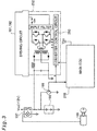
- Fig. 3 is a circuit diagram illustrating the internal structure of the converter 252 including the connections with the auxiliary machinery battery 198, the relay 197, and the main ECU 210.
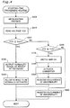
- Fig. 4 is a flowchart showing a series of processing executed by the master control CPU 272 in the main ECU 210.
- the converter 252 first smoothes the high voltage of the HV battery 194 and the driving circuits 191 and 192 by means of an input filter, converts the smoothed high voltage into alternating current in its transistor bridge circuit, and converts the high voltage alternating current into a low voltage by means of a transformer TR.
- the converted low voltage alternating current is subjected to rectifying and smoothing processes to eventually charge the auxiliary machinery battery 198.
- a converter control circuit 250 monitors the voltage VCE of the auxiliary machinery battery 198 measured by the voltage sensor 199 and controls the transistor bridge circuit to make the terminal voltage of the auxiliary machinery battery 198 constant.
- the terminal voltage of the auxiliary machinery battery 198 accordingly has a fixed value, regardless of the revolving speed of the engine 150.
- the converter control circuit 250 receives a control signal from the master control CPU 272 and causes the converter 252 to carry out the power conversion from the high voltage power source system to the low voltage power source system in response to the control signal at the high level.
- the master control CPU 272 receives the voltage signal VCE transmitted from the voltage sensor 199 mounted on the auxiliary machinery battery 198.
- The-relay 197 has a contact disposed in the power line of the auxiliary machinery battery 198. The voltage of the auxiliary machinery battery 198 is applied via the contact as the power source voltage Vcc for the electronic equipment including the main ECU 210.
- the master control CPU 272 In response to the supply of the power source voltage Vcc via the relay 197 in ON position, the master control CPU 272 starts the processing routine shown in the flowchart of Fig. 4.
- the master control CPU 272 first carries out a predetermined initialization process at step S300.
- the master control CPU 272 reads the voltage signal VCE of the voltage sensor 199 at step S310.
- the voltage signal VCE is subsequently compared with a preset minimum reference voltage Vmin at step S320.
- a specific value that establishes the low voltage power source Vcc and enables all-the ECUs to be normally activated is set to the minimum reference voltage Vmin.
- the minimum reference voltage Vmin is set equal to 10.5 V.
- the master control CPU 272 determines that there is no abnormality in the power source system and outputs a 'normality' signal, which represents the 'normal' state, as the result of diagnosis at step S330.
- the master control CPU 272 may output this signal independently or may alternatively output this signal after verification of the validity of the processing in the other ECUs.
- the master control CPU 272 starts an ordinary vehicle starting control specified in advance at step S340.
- the voltage VCE of the auxiliary machinery battery 198 is further compared with an operation inhibiting reference voltage Vinh, which is lower than the minimum reference voltage Vmin, at step S350.
- a specific value corresponding to a threshold value that ensures the normal operation of the system main relay SMR working with the low voltage power source is set to the operation inhibiting reference voltage Vinh.
- the operation inhibiting reference voltage Vinh is set equal to 8.5 V.
- the converter 252 works normally when the voltage of the auxiliary machinery battery 198 is not lower than the operation inhibiting reference voltage Vinh. This is because the operation guaranteed voltage of the converter 252 used in this embodiment is 8 V.
- the master control CPU 272 determines that the voltage of the auxiliary machinery battery 198 is too low to normally actuate the system main relay SMR, flashes the diagnosis lamp 291, and registers the occurrence of abnormality in the abnormality record registration circuit 280 at step S360. The program then goes to NEXT and exits from this processing routine.
- the master control CPU 272 may not function normally. In such cases, a power source monitoring circuit incorporated in each ECU keeps the ECU in the reset state. This arrangement prevents the master control CPU 272 from outputting any wrong signal to the converter control circuit 250.
- the master control CPU 272 switches the system main relay SMR on at step S370.
- the system main relay SMR closes its contact and allows the electric power output from the HV battery 194 to be supplied to the high voltage power line.
- the converter 252 accordingly receives the supply of electric power to be activated.
- the 'normality' signal output at step S330 as the result of diagnosis has not yet been output, so that the motor controller 260 does not actuate the motor MG1 or MG2.
- the master control CPU 272 After the system main relay SMR is switched on, the master control CPU 272 outputs the control signal to the converter control circuit 250 of the converter 252 and activates the converter 252 at step S380.
- the converter 252 accordingly carries out DC-DC conversion with the HV battery 194 as the power source and charges the auxiliary machinery battery 198.
- the procedure of the embodiment switches the system main relay SMR on, regardless of the voltage of the HV battery 194.
- the master control CPU 272 causes the battery ECU 230 to measure the voltage of the HV battery 194, prior to driving the system main relay SMR. In the case where the observed voltage of the HV battery 194 is insufficient, the procedure does not switch the system main relay SMR on, but registers the occurrence of abnormality in the abnormality record registration circuit 280.
- the procedure turns the system main relay SMR on and uses the converter 252 to charge the auxiliary machinery battery 198.
- the voltage VCE of the auxiliary machinery battery 198 is still lower than the expected range of the normal working voltage.
- the procedure accordingly detects the occurrence of abnormality, lights the diagnosis lamp 291 on, and registers the occurrence of abnormality in the abnormality record registration circuit 280 at step S390.
- the record of the occurrence of abnormality may be read from the abnormality record registration circuit 280 in a maintenance mode.
- the program then goes to NEXT and exits from this processing routine.
- the voltage VCE of the auxiliary machinery battery 198 increases to exceed the minimum reference voltage Vmin.
- the processing routine shown in the flowchart of Fig. 4 is repeatedly executed at preset intervals. With an increase in voltage VCE of the auxiliary machinery battery 198, the decision at step S320 eventually gives an affirmative answer.
- the 'normality' signal is accordingly output as the result of the diagnosis at step S330. All the ECUs start predetermined processes at once in response to the output of the 'normality' signal. This activates the vehicle and enables the driver to drive the vehicle.
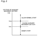
- Fig. 5 shows the three primary control procedures related to the magnitude of the voltage VCE of the auxiliary machinery battery 198.
- the hybrid vehicle of the embodiment constructed and controlled as discussed above does not immediately fall into the starting unable state. Even under such conditions, when it is allowed to convert the electric power of the HV battery 194 in the high voltage power source system into a low voltage by means of the converter 252 and supplement the voltage drop of the auxiliary machinery battery 198 (to or above 144 [V]), the converter 252 is immediately activated to supply the electrical energy to the low voltage power source system, thereby allowing the hybrid vehicle to start.
- the arrangement of the embodiment ensures a start of the hybrid vehicle, except when the terminal voltage of the auxiliary machinery battery 198 is lowered to or below the operation inhibiting voltage level (8.5 [V]) that represents the threshold value ensuring the normal operation of the system main relay SMR, which is one of the equipment for establishing the high voltage power source system.
- This arrangement significantly reduces the frequency of unsuccessful start due to the voltage drop of the auxiliary machinery battery 198.
- the master control CPU 272 even when the auxiliary machinery battery 198 is charged by means of the converter 252 to recover its voltage to the allowable level for starting the vehicle, the master control CPU 272 still registers the occurrence of abnormality in the abnormality record registration circuit 280 and flashes the diagnosis lamp 291 according to the requirements.
- This arrangement informs the driver of the occurrence of abnormality, that is, the unexpected voltage drop of the auxiliary machinery battery 198 and enables the driver to take any required measures, for example, maintenance of the vehicle.
- the technique of the present invention may be attained by another application, which is described below as a second embodiment of the present invention.
- the structure of the second embodiment uses the power source circuit to monitor the voltage of the auxiliary machinery battery 198 and compare the observed voltage VCE of the auxiliary machinery battery 198 with the minimum reference voltage Vmin and with the operation inhibiting reference voltage Vinh.
- the battery ECU 230 continuously monitors the voltage of the auxiliary machinery battery 198 and carries out the comparison with regard to the observed voltage VCE of the auxiliary machinery battery 198 in response to a starting requirement.
- VCE ⁇ Vinh the relay 197 is switched on to activate all the ECUs with the supply of the low voltage power source Vcc.
- the master control CPU 272 receives a flag F transmitted from the battery ECU 230.
- the flag F is set equal to 1 when Vinh ⁇ VCE ⁇ Vmin, and otherwise equal to 0 by the battery ECU 230.
- the master control CPU 272 executes a starting-time processing routine shown in the flowchart of Fig. 6.
- the master control CPU 272 caries out an initialization process and receives the flag F from the battery ECU 230, which is continuously active, through communications at step S410.
- the master control CPU 272 then reads a signal transmitted from the HV battery sensor 196 and measures a terminal voltage VH of the HV battery 194 at step S420.
- the observed terminal voltage VH is compared with a predetermined threshold value V0 at step S430.
- the predetermined threshold value V0 represents a voltage sufficient for charging the auxiliary machinery battery 198 by means of the converter 252.
- the chargeable or unchargeable decision depends upon the performance of the converter 252.
- the output of the converter 252 is stabilized at 14 [V] when the terminal voltage of the HV battery 194 is not lower than 144 [V]. This value is accordingly set to the predetermined threshold value V0.
- the master control CPU 272 switches on the system main relay SMR at step S440 and determines whether or not the value of the flag F received through communications is equal to one at step S450.
- the master control CPU 272 determines that the voltage of the auxiliary machinery battery 198 has been lower than the minimum reference value Vmin, registers the information representing the fact in the abnormality record registration circuit 280, and lights the diagnosis lamp 291 on at step S460.
- the master control CPU 272 then causes the whole master controller 270 to carry out normal starting operations at step S470.
- the master control CPU 272 keeps the system main relay SMR off at step S480 and carries out a high voltage abnormality process at step S490.
- the high voltage abnormality process registers the voltage drop in the abnormality record registration circuit 280.
- the process may additionally determine whether or not the HV battery 194 is chargeable by driving the engine 150. If chargeable, the process causes the engine ECU 240 to actuate the engine 150 and uses the motors MG1 and MG2 as the generators to charge the HV battery 194.
- the technique of the second embodiment enables the hybrid vehicle to start even when the voltage of the auxiliary machinery battery 198 is lower than the minimum reference voltage Vmin.
- the technique of the second embodiment additionally determines whether or not the auxiliary machinery battery 198 is chargeable by means of the converter 252 by taking into account the observed voltage of the HV battery 194.
- the converter 252 is not activated to charge the auxiliary machinery battery 198.
- the battery ECU 230 continuously monitors the voltage of the auxiliary machinery battery 198.
- this arrangement enables the driver to be warned at the earlier stage by alarm beeping or alarm light flashing.
- An applicable arrangement may even automatically turn off the light after confirming that the vehicle is at a stop.
- the technique of the present invention sets two reference voltages, that is, a minimum reference voltage and an operation inhibiting reference voltage, as the criteria for detecting the conditions of power supply of a low voltage power source system including a low voltage battery.
- the operation inhibiting reference voltage is lower than the minimum reference voltage and represents a threshold value ensuring the normal operation of an apparatus that establishes the power source of a high voltage power source system.
- a converter is activated to charge the low voltage battery, so as to recover the power source voltage of the low voltage battery to the minimum reference voltage.
- the whole system of, for example, a vehicle or an apparatus then functions normally.
- operation of the whole system is inhibited. This arrangement brings outs the best performance of the low voltage battery while assuring safety of the whole system.
Applications Claiming Priority (2)
| Application Number | Priority Date | Filing Date | Title |
|---|---|---|---|
| JP2000133297 | 2000-05-02 | ||
| JP2000133297A JP3381708B2 (ja) | 2000-05-02 | 2000-05-02 | 車両、電源系制御装置、電源系を制御する方法および車両の始動時制御方法 |
Publications (3)
| Publication Number | Publication Date |
|---|---|
| EP1151892A2 true EP1151892A2 (de) | 2001-11-07 |
| EP1151892A3 EP1151892A3 (de) | 2003-07-02 |
| EP1151892B1 EP1151892B1 (de) | 2015-07-29 |
Family
ID=18641819
Family Applications (1)
| Application Number | Title | Priority Date | Filing Date |
|---|---|---|---|
| EP01110393.4A Expired - Lifetime EP1151892B1 (de) | 2000-05-02 | 2001-04-26 | Fahrzeug mit einer Hochspannungsstromversorgung und Verfahren zum Starten eines solchen Fahrzeugs |
Country Status (3)
| Country | Link |
|---|---|
| US (1) | US6522960B2 (de) |
| EP (1) | EP1151892B1 (de) |
| JP (1) | JP3381708B2 (de) |
Cited By (21)
| Publication number | Priority date | Publication date | Assignee | Title |
|---|---|---|---|---|
| EP1369285A1 (de) * | 2002-06-05 | 2003-12-10 | Peugeot Citroen Automobiles SA | Verfahren und Vorrichtung zum Anlassen einer Brennkraftmaschine eines seriellen Hybridfahrzeugs |
| WO2006072815A2 (en) * | 2004-09-08 | 2006-07-13 | Eaton Corporation | Battery control system for hybrid vehicle and method for controlling a hybrid vehicle battery |
| WO2007057757A1 (en) * | 2005-11-21 | 2007-05-24 | Toyota Jidosha Kabushiki Kaisha | Power supply controller |
| EP1832464A2 (de) * | 2006-03-08 | 2007-09-12 | Denso Corporation | Umprogrammiersystem und elektronische Steuereinheit für ein Hybridfahrzeug |
| EP1834830A1 (de) * | 2006-03-17 | 2007-09-19 | Yamaha Hatsudoki Kabushiki Kaisha | Stromversorgung für elektrische Fahrzeuge |
| US7478692B2 (en) | 2003-11-05 | 2009-01-20 | Yamaha Hatsudoki Kabushiki Kaisha | Electric vehicle |
| WO2009036208A1 (en) | 2007-09-11 | 2009-03-19 | Hydro-Gear Limited Partnership | Control systems and methods for electric drive utility vehicles |
| US7527111B2 (en) | 2005-06-23 | 2009-05-05 | Yamaha Hatsudoki Kabushiki Kaisha | Driving device for hybrid vehicle, and hybrid vehicle incorporating the same |
| DE102009028965A1 (de) | 2009-08-28 | 2011-03-03 | Robert Bosch Gmbh | Schaltung zum Betreiben eines Hilfsaggregat für den Start von Verbrennungsmaschinen |
| US7973499B2 (en) | 2006-06-01 | 2011-07-05 | Takeuchi Mfg. Co., Ltd. | Working vehicle |
| US7990105B2 (en) | 2006-03-17 | 2011-08-02 | Yamaha Hatsudoki Kabushiki Kaisha | Power supply device for a vehicle |
| US8002062B2 (en) | 2005-03-16 | 2011-08-23 | Yamaha Hatsudoki Kabushiki Kaisha | Drive unit for hybrid vehicle |
| US8055399B2 (en) | 2008-10-23 | 2011-11-08 | Hydro-Gear Limited Partnership | Control systems and methods for electric motors of utility vehicles |
| EP2055592A3 (de) * | 2007-11-04 | 2012-05-09 | GM Global Technology Operations LLC | Verfahren zum externen Laden eines Antriebsstrangs |
| US8207693B2 (en) | 2007-09-11 | 2012-06-26 | Hydro-Gear Limited Partnership | Controller assemblies for electric drive utility vehicles |
| US9073539B1 (en) | 2010-06-22 | 2015-07-07 | Hydro-Gear Limited Partnership | Auxiliary battery powered brake release assembly |
| EP2902244A3 (de) * | 2013-11-26 | 2016-01-20 | Ford Global Technologies, LLC | Verfahren zur Steuerung eines Mild-Hybrid-Elektrofahrzeugs |
| EP2823367A4 (de) * | 2012-03-07 | 2016-06-29 | Int Truck Intellectual Prop Co | Bordnetzzustandskontrolle für ein fahrzeug |
| EP3272573A3 (de) * | 2016-06-28 | 2018-04-11 | Toyota Motor Engineering & Manufacturing North America, Inc. | Mehrpunkt-notfall-responder-isolationssystem |
| US10804815B1 (en) | 2019-07-18 | 2020-10-13 | Ford Global Technologies, Llc | DC/AC inverter system supplied by integrated power networks to increase output power with robust auto stop control |
| FR3116498A1 (fr) * | 2020-11-24 | 2022-05-27 | Psa Automobiles Sa | Procede utilisant un compteur d’etat d’une batterie. |
Families Citing this family (67)
| Publication number | Priority date | Publication date | Assignee | Title |
|---|---|---|---|---|
| US7145263B2 (en) * | 2001-10-30 | 2006-12-05 | Lear Corporation | Automatic headrest adjustment control system for a vehicle seat assembly |
| AT500328B1 (de) * | 2002-02-07 | 2010-03-15 | Elin Ebg Traction Gmbh | Fahrzeug mit einem elektrischen antrieb und verfahren zum betrieb eines solchen fahrzeuges |
| JP4042467B2 (ja) * | 2002-05-13 | 2008-02-06 | トヨタ自動車株式会社 | 信号処理装置 |
| US6952160B1 (en) * | 2002-08-07 | 2005-10-04 | Ford Global Technologies, Llc | Method and apparatus, for identifying the location of pressure sensors in a tire pressure monitoring system |
| US7245033B2 (en) * | 2002-11-21 | 2007-07-17 | Energy & Engine Technology Corporation | Auxiliary heating and air conditioning unit for a diesel powered transport vehicle |
| JP3661689B2 (ja) * | 2003-03-11 | 2005-06-15 | トヨタ自動車株式会社 | モータ駆動装置、それを備えるハイブリッド車駆動装置、モータ駆動装置の制御をコンピュータに実行させるプログラムを記録したコンピュータ読取り可能な記録媒体 |
| DE10312481A1 (de) * | 2003-03-20 | 2004-10-14 | Lucas Automotive Gmbh | Verfahren und System zur Früherkennung eines Ausfalls eines elektrisch gesteuerten Bremssystems |
| JP2004320877A (ja) * | 2003-04-15 | 2004-11-11 | Toyota Motor Corp | 駆動装置用の電力装置およびこれを備える自動車並びに電力装置の制御方法 |
| JP2005027467A (ja) * | 2003-07-04 | 2005-01-27 | Honda Motor Co Ltd | ハイブリッド車両の制御装置 |
| EP1671409A2 (de) * | 2003-10-08 | 2006-06-21 | Energy & Engine Technology Corporation | Verfahren und system zur verwaltung der batterieleistung |
| US7449793B2 (en) * | 2004-02-18 | 2008-11-11 | Bluwav Systems, Llc | Portable range extender with autonomous control of starting and stopping operations |
| JP4539114B2 (ja) * | 2004-02-25 | 2010-09-08 | トヨタ自動車株式会社 | 駆動システムおよびこれを搭載した自動車 |
| KR100605820B1 (ko) * | 2004-03-22 | 2006-08-01 | 삼성전자주식회사 | 피디에이 기능과 폰 기능을 구비한 피디에이폰에서사용자데이터 보호방법 |
| JP4438595B2 (ja) * | 2004-10-18 | 2010-03-24 | トヨタ自動車株式会社 | 車両の制御装置 |
| JP4239949B2 (ja) * | 2004-10-26 | 2009-03-18 | トヨタ自動車株式会社 | ハイブリッド制御システム |
| JP4379412B2 (ja) * | 2005-12-05 | 2009-12-09 | トヨタ自動車株式会社 | パワーステアリング用電源制御装置 |
| US8365852B2 (en) * | 2005-12-21 | 2013-02-05 | Ford Global Technologies, Llc | Power supply system and method for powering a vehicle |
| US7970518B2 (en) * | 2005-12-22 | 2011-06-28 | Caterpillar Inc. | Method and system for keyless machine operation |
| US8100210B2 (en) * | 2006-02-07 | 2012-01-24 | Takeuchi Mfg. Co., Ltd | Electrically driven industrial vehicle |
| US8111036B2 (en) * | 2006-03-27 | 2012-02-07 | Stephen George Rosenstock | System for electrically connecting and disconnecting a vehicle generator from a vehicle storage unit |
| JP4538427B2 (ja) * | 2006-06-01 | 2010-09-08 | 株式会社竹内製作所 | 作業用車両 |
| JP4284334B2 (ja) * | 2006-06-01 | 2009-06-24 | 株式会社竹内製作所 | 作業用車両 |
| JP4245624B2 (ja) | 2006-09-20 | 2009-03-25 | トヨタ自動車株式会社 | ハイブリッド車両の電源制御装置および電源制御方法 |
| JP4952229B2 (ja) * | 2006-12-18 | 2012-06-13 | トヨタ自動車株式会社 | 電源回路の制御装置 |
| JP4734268B2 (ja) * | 2007-02-13 | 2011-07-27 | プライムアースEvエナジー株式会社 | 放電システム、および電動車両 |
| JP2008201301A (ja) * | 2007-02-21 | 2008-09-04 | Toyota Motor Corp | 駆動システムおよびこれを搭載する自動車 |
| JP4811301B2 (ja) * | 2007-03-06 | 2011-11-09 | トヨタ自動車株式会社 | 二次電池の入出力制御装置、および車両 |
| JP5036416B2 (ja) * | 2007-06-15 | 2012-09-26 | トヨタ自動車株式会社 | 電源システムおよびそれを備えた車両、ならびに充放電制御方法 |
| JP4812699B2 (ja) * | 2007-06-21 | 2011-11-09 | 日立オートモティブシステムズ株式会社 | 電源制御装置 |
| US9067483B2 (en) * | 2008-10-21 | 2015-06-30 | Maurice W. Raynor | Electric vechicle drive mechanism for driving multiple alternators |
| US8319472B2 (en) | 2009-01-19 | 2012-11-27 | GM Global Technology Operations LLC | Method and system for internally jump-starting an engine |
| US8099936B2 (en) * | 2009-01-27 | 2012-01-24 | Textron Innovations Inc. | Electrically powered flail mower |
| JP5310640B2 (ja) * | 2010-04-20 | 2013-10-09 | トヨタ自動車株式会社 | 駆動装置 |
| JP5484192B2 (ja) * | 2010-05-20 | 2014-05-07 | 本田技研工業株式会社 | 電動車両の始動制御装置 |
| JP5504117B2 (ja) * | 2010-09-28 | 2014-05-28 | 本田技研工業株式会社 | 電気自動車の制御装置 |
| KR101189292B1 (ko) * | 2010-11-30 | 2012-10-09 | 현대자동차주식회사 | Isg 차량의 배터리 센서 비활성화 안내 장치 및 방법 |
| US8742615B2 (en) | 2011-01-14 | 2014-06-03 | GM Global Technology Operations LLC | Method and apparatus for electric power management in a vehicle |
| JP5561206B2 (ja) * | 2011-02-25 | 2014-07-30 | 株式会社デンソー | バッテリの充電制御装置 |
| KR101229441B1 (ko) * | 2011-03-18 | 2013-02-06 | 주식회사 만도 | 배터리 충전 장치 |
| KR101273060B1 (ko) * | 2011-03-28 | 2013-06-10 | 기아자동차주식회사 | 전기차량의 보조배터리 관리방법 |
| JP2013090464A (ja) * | 2011-10-19 | 2013-05-13 | Toyota Motor Corp | 車両 |
| JP2013158174A (ja) * | 2012-01-31 | 2013-08-15 | Toyota Motor Corp | 車速制御装置およびそれを搭載した車両 |
| JP2013165623A (ja) * | 2012-02-13 | 2013-08-22 | Denso Corp | 電力変換装置 |
| JP5906786B2 (ja) * | 2012-02-15 | 2016-04-20 | いすゞ自動車株式会社 | 自動車用電源システム、車両、及び車両の電気供給方法 |
| JP5887982B2 (ja) * | 2012-02-15 | 2016-03-16 | いすゞ自動車株式会社 | 自動車用電源システム、車両、及び車両の電気供給方法 |
| JP5982902B2 (ja) * | 2012-03-15 | 2016-08-31 | 日産自動車株式会社 | 車両の制御装置 |
| US11084485B2 (en) * | 2012-07-24 | 2021-08-10 | Magna Steyr Fahrzeugtechnik Ag & Co Kg | Method for operating a hybrid vehicle |
| JP5830449B2 (ja) * | 2012-08-30 | 2015-12-09 | 日立オートモティブシステムズ株式会社 | 電動車駆動システム |
| JP5974108B2 (ja) * | 2012-10-01 | 2016-08-23 | 日立オートモティブシステムズ株式会社 | 電動車両の制御装置 |
| JP5729401B2 (ja) * | 2013-02-01 | 2015-06-03 | トヨタ自動車株式会社 | 電動車両 |
| KR101500119B1 (ko) | 2013-08-09 | 2015-03-06 | 현대자동차주식회사 | 하이브리드 차량의 저전압 직류변환장치 제어 방법 |
| JP5850017B2 (ja) | 2013-10-15 | 2016-02-03 | 株式会社デンソー | バッテリ監視装置 |
| US10343545B2 (en) | 2016-01-15 | 2019-07-09 | Trumpet Holdings, Inc. | Systems and methods for separating batteries |
| WO2018016087A1 (ja) * | 2016-07-22 | 2018-01-25 | 新電元工業株式会社 | ハイブリッド車両用電力供給装置、ハイブリッド車両用電力供給システム、および、ハイブリッド車両用電力供給装置の制御方法 |
| JP6807018B2 (ja) * | 2016-10-03 | 2021-01-06 | 株式会社Gsユアサ | 車両用の蓄電装置、及び車両 |
| US10396647B2 (en) * | 2016-10-10 | 2019-08-27 | Mando Corporation | Converter controlling device for hybrid vehicle and converter controlling method for hybrid vehicle |
| TWI621552B (zh) * | 2016-12-02 | 2018-04-21 | 姚立和 | 電動車緊急啓動裝置 |
| KR102463704B1 (ko) * | 2016-12-16 | 2022-11-07 | 현대자동차주식회사 | 차량의 시동 제어 장치 및 방법 |
| JP6737197B2 (ja) * | 2017-02-08 | 2020-08-05 | トヨタ自動車株式会社 | 電源システム |
| US9834206B1 (en) * | 2017-03-29 | 2017-12-05 | Ford Global Technologies, Llc | Fault-tolerant operation of hybrid electric vehicle |
| CN108656976B (zh) * | 2017-04-01 | 2021-04-13 | 北京海博思创科技股份有限公司 | 电池管理系统 |
| JP6822456B2 (ja) * | 2017-09-22 | 2021-01-27 | 株式会社デンソー | 車両電源システム、および電源制御装置 |
| CN109306930A (zh) * | 2018-09-12 | 2019-02-05 | 中国航发湖南动力机械研究所 | 发动机起动装置及发动机系统 |
| JP7373114B2 (ja) * | 2019-05-28 | 2023-11-02 | マツダ株式会社 | 車両用電源制御装置 |
| US11225211B1 (en) | 2020-08-25 | 2022-01-18 | Fca Us Llc | Vehicle power supply backup |
| FR3119893B1 (fr) * | 2021-02-18 | 2024-03-29 | Psa Automobiles Sa | Surveillance de l’état d’une batterie de servitude d’un véhicule à gmp mhev |
| DE102021113931A1 (de) | 2021-05-28 | 2022-12-01 | Elringklinger Ag | Kontrollvorrichtung für einen Brennstoffzellen-elektrischen Antrieb |
Citations (1)
| Publication number | Priority date | Publication date | Assignee | Title |
|---|---|---|---|---|
| US5798629A (en) | 1995-06-07 | 1998-08-25 | Nissan Motor Co., Ltd. | Apparatus for diagnosing low voltage battery |
Family Cites Families (9)
| Publication number | Priority date | Publication date | Assignee | Title |
|---|---|---|---|---|
| JPS6485502A (en) | 1987-09-24 | 1989-03-30 | Toyota Motor Corp | Controller for electric automobile |
| JP3039119B2 (ja) * | 1992-03-31 | 2000-05-08 | 日産自動車株式会社 | 車両用電源装置 |
| JP3491714B2 (ja) * | 1995-06-14 | 2004-01-26 | 本田技研工業株式会社 | 電動車の電池過放電防止装置 |
| JP3245334B2 (ja) * | 1995-08-03 | 2002-01-15 | 本田技研工業株式会社 | 電動車両の電源制御装置 |
| JP3524661B2 (ja) * | 1995-12-08 | 2004-05-10 | 本田技研工業株式会社 | 電動車両の電源制御装置 |
| US6081098A (en) * | 1997-11-03 | 2000-06-27 | Midtronics, Inc. | Method and apparatus for charging a battery |
| JP3294532B2 (ja) | 1997-06-19 | 2002-06-24 | 株式会社デンソー | ハイブリッド車制御装置 |
| JPH11136801A (ja) * | 1997-10-24 | 1999-05-21 | Denso Corp | 複数バッテリ型電気自動車用駆動装置 |
| JP3450220B2 (ja) * | 1999-04-16 | 2003-09-22 | 三菱電機株式会社 | 車両用電源装置 |
-
2000
- 2000-05-02 JP JP2000133297A patent/JP3381708B2/ja not_active Expired - Lifetime
-
2001
- 2001-04-13 US US09/833,582 patent/US6522960B2/en not_active Expired - Lifetime
- 2001-04-26 EP EP01110393.4A patent/EP1151892B1/de not_active Expired - Lifetime
Patent Citations (1)
| Publication number | Priority date | Publication date | Assignee | Title |
|---|---|---|---|---|
| US5798629A (en) | 1995-06-07 | 1998-08-25 | Nissan Motor Co., Ltd. | Apparatus for diagnosing low voltage battery |
Cited By (43)
| Publication number | Priority date | Publication date | Assignee | Title |
|---|---|---|---|---|
| FR2840654A1 (fr) * | 2002-06-05 | 2003-12-12 | Peugeot Citroen Automobiles Sa | Procede et dispositif de demarrage d'un moteur thermique dans un vehicule hybride serie |
| EP1369285A1 (de) * | 2002-06-05 | 2003-12-10 | Peugeot Citroen Automobiles SA | Verfahren und Vorrichtung zum Anlassen einer Brennkraftmaschine eines seriellen Hybridfahrzeugs |
| US7478692B2 (en) | 2003-11-05 | 2009-01-20 | Yamaha Hatsudoki Kabushiki Kaisha | Electric vehicle |
| US7489101B2 (en) | 2004-09-08 | 2009-02-10 | Eaton Corporation | Battery control system for hybrid vehicle and method for controlling a hybrid vehicle battery |
| WO2006072815A2 (en) * | 2004-09-08 | 2006-07-13 | Eaton Corporation | Battery control system for hybrid vehicle and method for controlling a hybrid vehicle battery |
| WO2006072815A3 (en) * | 2004-09-08 | 2006-09-21 | Eaton Corp | Battery control system for hybrid vehicle and method for controlling a hybrid vehicle battery |
| CN101052544B (zh) * | 2004-09-08 | 2014-06-18 | 易通公司 | 混合动力车辆的电池控制系统和控制混合动力车辆电池的方法 |
| US8002062B2 (en) | 2005-03-16 | 2011-08-23 | Yamaha Hatsudoki Kabushiki Kaisha | Drive unit for hybrid vehicle |
| US7527111B2 (en) | 2005-06-23 | 2009-05-05 | Yamaha Hatsudoki Kabushiki Kaisha | Driving device for hybrid vehicle, and hybrid vehicle incorporating the same |
| WO2007057757A1 (en) * | 2005-11-21 | 2007-05-24 | Toyota Jidosha Kabushiki Kaisha | Power supply controller |
| EP1832464A3 (de) * | 2006-03-08 | 2008-10-15 | Denso Corporation | Umprogrammiersystem und elektronische Steuereinheit für ein Hybridfahrzeug |
| EP1832464A2 (de) * | 2006-03-08 | 2007-09-12 | Denso Corporation | Umprogrammiersystem und elektronische Steuereinheit für ein Hybridfahrzeug |
| EP1834830A1 (de) * | 2006-03-17 | 2007-09-19 | Yamaha Hatsudoki Kabushiki Kaisha | Stromversorgung für elektrische Fahrzeuge |
| US7667342B2 (en) | 2006-03-17 | 2010-02-23 | Yamaha Hatsudoki Kabushiki Kaisha | Power supply for a vehicle |
| US7990105B2 (en) | 2006-03-17 | 2011-08-02 | Yamaha Hatsudoki Kabushiki Kaisha | Power supply device for a vehicle |
| US7973499B2 (en) | 2006-06-01 | 2011-07-05 | Takeuchi Mfg. Co., Ltd. | Working vehicle |
| US8207693B2 (en) | 2007-09-11 | 2012-06-26 | Hydro-Gear Limited Partnership | Controller assemblies for electric drive utility vehicles |
| US8668036B2 (en) | 2007-09-11 | 2014-03-11 | Hydro-Gear Limited Partnership | Control systems and methods for electric drive utility vehicles |
| US10440880B2 (en) | 2007-09-11 | 2019-10-15 | Hydro-Gear Limited Partnership | Control systems and methods for electric drive utility vehicles |
| US9409578B2 (en) | 2007-09-11 | 2016-08-09 | Hydro-Gear Limited Partnership | Electric drive vehicle control system |
| US8234026B2 (en) | 2007-09-11 | 2012-07-31 | Hydro-Gear Limited Partnership | Electric drive vehicle control system |
| US8849490B2 (en) | 2007-09-11 | 2014-09-30 | Hydro-Gear Limited Partnership | Electric drive vehicle control system |
| US8450953B2 (en) | 2007-09-11 | 2013-05-28 | Hydro-Gear Limited Partnership | Controller assemblies for electric drive utility vehicles |
| WO2009036208A1 (en) | 2007-09-11 | 2009-03-19 | Hydro-Gear Limited Partnership | Control systems and methods for electric drive utility vehicles |
| EP2055592A3 (de) * | 2007-11-04 | 2012-05-09 | GM Global Technology Operations LLC | Verfahren zum externen Laden eines Antriebsstrangs |
| US9408343B2 (en) | 2008-10-23 | 2016-08-09 | Hydro-Gear Limited Partnership | Control systems and methods for electric motors of utility vehicles |
| US8548694B2 (en) | 2008-10-23 | 2013-10-01 | Hydro-Gear Limited Partnership | Control systems and methods for electric motors of utility vehicles |
| US8296003B2 (en) | 2008-10-23 | 2012-10-23 | Hydro-Gear Limited Partnership | Control systems and methods for electric motors of utility vehicles |
| US8965630B2 (en) | 2008-10-23 | 2015-02-24 | Hydro-Gear Limited Partnership | Control systems and methods for electric motors of utility vehicles |
| US8055399B2 (en) | 2008-10-23 | 2011-11-08 | Hydro-Gear Limited Partnership | Control systems and methods for electric motors of utility vehicles |
| EP2346709A4 (de) * | 2008-10-23 | 2015-07-22 | Hydro Gear Ltd Partnership | Steuersysteme und verfahren für nutzfahrzeuge mit elektromotoren |
| DE102009028965A1 (de) | 2009-08-28 | 2011-03-03 | Robert Bosch Gmbh | Schaltung zum Betreiben eines Hilfsaggregat für den Start von Verbrennungsmaschinen |
| US9190869B2 (en) | 2009-08-28 | 2015-11-17 | Robert Bosch Gmbh | Circuit for operating an auxiliary unit for starting internal combustion engines |
| WO2011023438A1 (de) | 2009-08-28 | 2011-03-03 | Robert Bosch Gmbh | Schaltung zum betreiben eines hilfsaggregat für den start von verbrennungsmaschinen |
| US9073539B1 (en) | 2010-06-22 | 2015-07-07 | Hydro-Gear Limited Partnership | Auxiliary battery powered brake release assembly |
| EP2823367A4 (de) * | 2012-03-07 | 2016-06-29 | Int Truck Intellectual Prop Co | Bordnetzzustandskontrolle für ein fahrzeug |
| EP2902244A3 (de) * | 2013-11-26 | 2016-01-20 | Ford Global Technologies, LLC | Verfahren zur Steuerung eines Mild-Hybrid-Elektrofahrzeugs |
| RU2676923C2 (ru) * | 2013-11-26 | 2019-01-11 | Форд Глобал Технолоджис, ЛЛК | Способ управления гибридной силовой установкой транспортного средства и транспортное средство |
| EP3272573A3 (de) * | 2016-06-28 | 2018-04-11 | Toyota Motor Engineering & Manufacturing North America, Inc. | Mehrpunkt-notfall-responder-isolationssystem |
| US10086705B2 (en) | 2016-06-28 | 2018-10-02 | Toyota Motor Engineering & Manufacturing North America, Inc. | Multipoint emergency responder safety isolation system |
| US10804815B1 (en) | 2019-07-18 | 2020-10-13 | Ford Global Technologies, Llc | DC/AC inverter system supplied by integrated power networks to increase output power with robust auto stop control |
| FR3116498A1 (fr) * | 2020-11-24 | 2022-05-27 | Psa Automobiles Sa | Procede utilisant un compteur d’etat d’une batterie. |
| WO2022112671A1 (fr) * | 2020-11-24 | 2022-06-02 | Psa Automobiles Sa | Procede utilisant un compteur d'etat d'une batterie |
Also Published As
| Publication number | Publication date |
|---|---|
| EP1151892B1 (de) | 2015-07-29 |
| US20010041952A1 (en) | 2001-11-15 |
| US6522960B2 (en) | 2003-02-18 |
| EP1151892A3 (de) | 2003-07-02 |
| JP2001320807A (ja) | 2001-11-16 |
| JP3381708B2 (ja) | 2003-03-04 |
Similar Documents
| Publication | Publication Date | Title |
|---|---|---|
| EP1151892B1 (de) | Fahrzeug mit einer Hochspannungsstromversorgung und Verfahren zum Starten eines solchen Fahrzeugs | |
| JP3736300B2 (ja) | 自動車、およびその電源装置 | |
| JP3304777B2 (ja) | 電動車両 | |
| US8476865B2 (en) | Control device and method for charge control | |
| US6727676B2 (en) | Control device for hybrid vehicle | |
| JP3568840B2 (ja) | ハイブリッド車両の制御装置 | |
| US5714851A (en) | Serial hybrid drive arrangement for a motor vehicle | |
| EP3046198A1 (de) | Elektrisches energiespeichersystem | |
| US20090315518A1 (en) | Power supply device and vehicle | |
| US11325500B2 (en) | On-board electrical network for a motor vehicle | |
| JP2000023307A (ja) | ハイブリッド車両のバッテリー制御装置 | |
| US10483841B2 (en) | Motor vehicle | |
| JP2004003453A (ja) | 動力出力装置およびこれを備える自動車 | |
| US10730509B2 (en) | Fail-safe method for parallel hybrid electric vehicle | |
| KR100844729B1 (ko) | 하이브리드 차량의 비상 구동 장치 및 방법 | |
| JP2002176704A (ja) | 二電源系を有するハイブリッド自動車の駆動装置 | |
| US10099680B2 (en) | Hybrid vehicle | |
| JP2000324615A (ja) | 動力出力装置およびそれを搭載したハイブリッド車両並びに動力出力装置の制御方法 | |
| JP7373113B2 (ja) | 車両用電源制御装置 | |
| JP2005532777A (ja) | 熱機関と少なくとも一つの電気機械とを含むモータビークル(自動車)のための動力伝達方法および装置 | |
| JP3044962B2 (ja) | エンジン駆動発電機付電気自動車のモータ制御装置 | |
| US20190193564A1 (en) | Electrically driven vehicle | |
| JP4285638B2 (ja) | 車両の充電制御装置 | |
| JPH09271102A (ja) | 電動車両 | |
| JP2005022561A (ja) | 車両の充電制御装置 |
Legal Events
| Date | Code | Title | Description |
|---|---|---|---|
| PUAI | Public reference made under article 153(3) epc to a published international application that has entered the european phase |
Free format text: ORIGINAL CODE: 0009012 |
|
| 17P | Request for examination filed |
Effective date: 20010426 |
|
| AK | Designated contracting states |
Kind code of ref document: A2 Designated state(s): AT BE CH CY DE DK ES FI FR GB GR IE IT LI LU MC NL PT SE TR |
|
| AX | Request for extension of the european patent |
Free format text: AL;LT;LV;MK;RO;SI |
|
| PUAL | Search report despatched |
Free format text: ORIGINAL CODE: 0009013 |
|
| AK | Designated contracting states |
Designated state(s): AT BE CH CY DE DK ES FI FR GB GR IE IT LI LU MC NL PT SE TR |
|
| AX | Request for extension of the european patent |
Extension state: AL LT LV MK RO SI |
|
| AKX | Designation fees paid |
Designated state(s): DE FR GB |
|
| 17Q | First examination report despatched |
Effective date: 20090703 |
|
| RAP1 | Party data changed (applicant data changed or rights of an application transferred) |
Owner name: TOYOTA JIDOSHA KABUSHIKI KAISHA |
|
| GRAP | Despatch of communication of intention to grant a patent |
Free format text: ORIGINAL CODE: EPIDOSNIGR1 |
|
| INTG | Intention to grant announced |
Effective date: 20150213 |
|
| RIN1 | Information on inventor provided before grant (corrected) |
Inventor name: NADA, MITSUHIRO |
|
| GRAS | Grant fee paid |
Free format text: ORIGINAL CODE: EPIDOSNIGR3 |
|
| GRAA | (expected) grant |
Free format text: ORIGINAL CODE: 0009210 |
|
| AK | Designated contracting states |
Kind code of ref document: B1 Designated state(s): DE FR GB |
|
| REG | Reference to a national code |
Ref country code: GB Ref legal event code: FG4D |
|
| REG | Reference to a national code |
Ref country code: DE Ref legal event code: R096 Ref document number: 60149476 Country of ref document: DE |
|
| REG | Reference to a national code |
Ref country code: DE Ref legal event code: R084 Ref document number: 60149476 Country of ref document: DE |
|
| REG | Reference to a national code |
Ref country code: GB Ref legal event code: 746 Effective date: 20160120 |
|
| REG | Reference to a national code |
Ref country code: FR Ref legal event code: PLFP Year of fee payment: 16 |
|
| REG | Reference to a national code |
Ref country code: DE Ref legal event code: R097 Ref document number: 60149476 Country of ref document: DE |
|
| PLBE | No opposition filed within time limit |
Free format text: ORIGINAL CODE: 0009261 |
|
| STAA | Information on the status of an ep patent application or granted ep patent |
Free format text: STATUS: NO OPPOSITION FILED WITHIN TIME LIMIT |
|
| 26N | No opposition filed |
Effective date: 20160502 |
|
| REG | Reference to a national code |
Ref country code: FR Ref legal event code: PLFP Year of fee payment: 17 |
|
| REG | Reference to a national code |
Ref country code: FR Ref legal event code: PLFP Year of fee payment: 18 |
|
| PGFP | Annual fee paid to national office [announced via postgrant information from national office to epo] |
Ref country code: FR Payment date: 20200312 Year of fee payment: 20 |
|
| PGFP | Annual fee paid to national office [announced via postgrant information from national office to epo] |
Ref country code: DE Payment date: 20200415 Year of fee payment: 20 |
|
| PGFP | Annual fee paid to national office [announced via postgrant information from national office to epo] |
Ref country code: GB Payment date: 20200416 Year of fee payment: 20 |
|
| REG | Reference to a national code |
Ref country code: DE Ref legal event code: R071 Ref document number: 60149476 Country of ref document: DE |
|
| REG | Reference to a national code |
Ref country code: GB Ref legal event code: PE20 Expiry date: 20210425 |
|
| PG25 | Lapsed in a contracting state [announced via postgrant information from national office to epo] |
Ref country code: GB Free format text: LAPSE BECAUSE OF EXPIRATION OF PROTECTION Effective date: 20210425 |