EP1142916B1 - Gasphasenpolymerisationsverfahren mit Direktkühlsystem - Google Patents
Gasphasenpolymerisationsverfahren mit Direktkühlsystem Download PDFInfo
- Publication number
- EP1142916B1 EP1142916B1 EP01108292A EP01108292A EP1142916B1 EP 1142916 B1 EP1142916 B1 EP 1142916B1 EP 01108292 A EP01108292 A EP 01108292A EP 01108292 A EP01108292 A EP 01108292A EP 1142916 B1 EP1142916 B1 EP 1142916B1
- Authority
- EP
- European Patent Office
- Prior art keywords
- gas
- fluidized
- phase polymerization
- coolant
- fluidizing gas
- Prior art date
- Legal status (The legal status is an assumption and is not a legal conclusion. Google has not performed a legal analysis and makes no representation as to the accuracy of the status listed.)
- Expired - Lifetime
Links
- 238000001816 cooling Methods 0.000 title claims description 90
- 238000000034 method Methods 0.000 title claims description 45
- 238000012685 gas phase polymerization Methods 0.000 title claims description 32
- 239000002826 coolant Substances 0.000 claims description 43
- 239000007788 liquid Substances 0.000 claims description 31
- 238000006243 chemical reaction Methods 0.000 claims description 25
- 238000006116 polymerization reaction Methods 0.000 claims description 25
- 239000000178 monomer Substances 0.000 claims description 17
- 239000000110 cooling liquid Substances 0.000 claims description 14
- 239000000203 mixture Substances 0.000 claims description 12
- 239000012530 fluid Substances 0.000 claims description 9
- 239000003054 catalyst Substances 0.000 claims description 8
- 229920000098 polyolefin Polymers 0.000 claims description 8
- VLKZOEOYAKHREP-UHFFFAOYSA-N n-Hexane Chemical compound CCCCCC VLKZOEOYAKHREP-UHFFFAOYSA-N 0.000 claims description 6
- VGGSQFUCUMXWEO-UHFFFAOYSA-N Ethene Chemical compound C=C VGGSQFUCUMXWEO-UHFFFAOYSA-N 0.000 claims description 5
- 239000005977 Ethylene Substances 0.000 claims description 5
- OFBQJSOFQDEBGM-UHFFFAOYSA-N Pentane Chemical compound CCCCC OFBQJSOFQDEBGM-UHFFFAOYSA-N 0.000 claims description 5
- 238000004519 manufacturing process Methods 0.000 claims description 5
- -1 polyethylene Polymers 0.000 claims description 5
- 239000004698 Polyethylene Substances 0.000 claims description 4
- 229920000573 polyethylene Polymers 0.000 claims description 4
- 238000011144 upstream manufacturing Methods 0.000 claims description 4
- 238000012856 packing Methods 0.000 claims description 3
- 125000000753 cycloalkyl group Chemical group 0.000 claims description 2
- 229920006395 saturated elastomer Polymers 0.000 claims description 2
- 125000004432 carbon atom Chemical group C* 0.000 claims 3
- 238000000746 purification Methods 0.000 claims 3
- 239000012716 precipitator Substances 0.000 claims 2
- 239000007795 chemical reaction product Substances 0.000 claims 1
- 239000000047 product Substances 0.000 claims 1
- 239000004711 α-olefin Substances 0.000 claims 1
- 239000007789 gas Substances 0.000 description 104
- 229920000642 polymer Polymers 0.000 description 15
- 238000000926 separation method Methods 0.000 description 9
- 238000012546 transfer Methods 0.000 description 9
- 239000000428 dust Substances 0.000 description 8
- 239000002245 particle Substances 0.000 description 8
- 150000001336 alkenes Chemical class 0.000 description 4
- 230000015572 biosynthetic process Effects 0.000 description 4
- 238000009835 boiling Methods 0.000 description 4
- 238000004140 cleaning Methods 0.000 description 4
- 230000008021 deposition Effects 0.000 description 4
- 238000009833 condensation Methods 0.000 description 3
- 230000005494 condensation Effects 0.000 description 3
- 239000002216 antistatic agent Substances 0.000 description 2
- 238000000576 coating method Methods 0.000 description 2
- 239000000498 cooling water Substances 0.000 description 2
- 238000013461 design Methods 0.000 description 2
- 238000009826 distribution Methods 0.000 description 2
- 230000000694 effects Effects 0.000 description 2
- 229920001971 elastomer Polymers 0.000 description 2
- 230000017525 heat dissipation Effects 0.000 description 2
- 238000002347 injection Methods 0.000 description 2
- 239000007924 injection Substances 0.000 description 2
- 239000000463 material Substances 0.000 description 2
- 238000010327 methods by industry Methods 0.000 description 2
- 239000000843 powder Substances 0.000 description 2
- 238000012545 processing Methods 0.000 description 2
- 239000005060 rubber Substances 0.000 description 2
- 239000007787 solid Substances 0.000 description 2
- 239000000126 substance Substances 0.000 description 2
- 238000005406 washing Methods 0.000 description 2
- UFHFLCQGNIYNRP-UHFFFAOYSA-N Hydrogen Chemical compound [H][H] UFHFLCQGNIYNRP-UHFFFAOYSA-N 0.000 description 1
- 239000000654 additive Substances 0.000 description 1
- 230000000996 additive effect Effects 0.000 description 1
- 150000001335 aliphatic alkanes Chemical class 0.000 description 1
- CWNKMHIETKEBCA-UHFFFAOYSA-N alpha-Ethylaminohexanophenone Chemical compound CCCCC(NCC)C(=O)C1=CC=CC=C1 CWNKMHIETKEBCA-UHFFFAOYSA-N 0.000 description 1
- 239000001273 butane Substances 0.000 description 1
- 239000012159 carrier gas Substances 0.000 description 1
- 239000003426 co-catalyst Substances 0.000 description 1
- 239000012809 cooling fluid Substances 0.000 description 1
- 150000001924 cycloalkanes Chemical class 0.000 description 1
- 238000000354 decomposition reaction Methods 0.000 description 1
- 230000001419 dependent effect Effects 0.000 description 1
- 230000000994 depressogenic effect Effects 0.000 description 1
- 239000000539 dimer Substances 0.000 description 1
- 230000005611 electricity Effects 0.000 description 1
- 238000001704 evaporation Methods 0.000 description 1
- 239000004744 fabric Substances 0.000 description 1
- 238000011010 flushing procedure Methods 0.000 description 1
- 239000001257 hydrogen Substances 0.000 description 1
- 229910052739 hydrogen Inorganic materials 0.000 description 1
- 238000002844 melting Methods 0.000 description 1
- 230000008018 melting Effects 0.000 description 1
- 238000012986 modification Methods 0.000 description 1
- 230000004048 modification Effects 0.000 description 1
- IJDNQMDRQITEOD-UHFFFAOYSA-N n-butane Chemical compound CCCC IJDNQMDRQITEOD-UHFFFAOYSA-N 0.000 description 1
- 238000005191 phase separation Methods 0.000 description 1
- 230000000704 physical effect Effects 0.000 description 1
- 230000000379 polymerizing effect Effects 0.000 description 1
- QQONPFPTGQHPMA-UHFFFAOYSA-N propylene Natural products CC=C QQONPFPTGQHPMA-UHFFFAOYSA-N 0.000 description 1
- 125000004805 propylene group Chemical group [H]C([H])([H])C([H])([*:1])C([H])([H])[*:2] 0.000 description 1
- 239000000376 reactant Substances 0.000 description 1
- 230000017986 regulation of heat dissipation Effects 0.000 description 1
- 239000000243 solution Substances 0.000 description 1
- 239000000725 suspension Substances 0.000 description 1
- 239000013638 trimer Substances 0.000 description 1
Images



Classifications
-
- C—CHEMISTRY; METALLURGY
- C08—ORGANIC MACROMOLECULAR COMPOUNDS; THEIR PREPARATION OR CHEMICAL WORKING-UP; COMPOSITIONS BASED THEREON
- C08F—MACROMOLECULAR COMPOUNDS OBTAINED BY REACTIONS ONLY INVOLVING CARBON-TO-CARBON UNSATURATED BONDS
- C08F2/00—Processes of polymerisation
- C08F2/34—Polymerisation in gaseous state
-
- B—PERFORMING OPERATIONS; TRANSPORTING
- B01—PHYSICAL OR CHEMICAL PROCESSES OR APPARATUS IN GENERAL
- B01J—CHEMICAL OR PHYSICAL PROCESSES, e.g. CATALYSIS OR COLLOID CHEMISTRY; THEIR RELEVANT APPARATUS
- B01J8/00—Chemical or physical processes in general, conducted in the presence of fluids and solid particles; Apparatus for such processes
- B01J8/18—Chemical or physical processes in general, conducted in the presence of fluids and solid particles; Apparatus for such processes with fluidised particles
- B01J8/1836—Heating and cooling the reactor
-
- B—PERFORMING OPERATIONS; TRANSPORTING
- B01—PHYSICAL OR CHEMICAL PROCESSES OR APPARATUS IN GENERAL
- B01J—CHEMICAL OR PHYSICAL PROCESSES, e.g. CATALYSIS OR COLLOID CHEMISTRY; THEIR RELEVANT APPARATUS
- B01J8/00—Chemical or physical processes in general, conducted in the presence of fluids and solid particles; Apparatus for such processes
- B01J8/005—Separating solid material from the gas/liquid stream
- B01J8/0055—Separating solid material from the gas/liquid stream using cyclones
-
- B—PERFORMING OPERATIONS; TRANSPORTING
- B01—PHYSICAL OR CHEMICAL PROCESSES OR APPARATUS IN GENERAL
- B01J—CHEMICAL OR PHYSICAL PROCESSES, e.g. CATALYSIS OR COLLOID CHEMISTRY; THEIR RELEVANT APPARATUS
- B01J8/00—Chemical or physical processes in general, conducted in the presence of fluids and solid particles; Apparatus for such processes
- B01J8/005—Separating solid material from the gas/liquid stream
- B01J8/006—Separating solid material from the gas/liquid stream by filtration
-
- C—CHEMISTRY; METALLURGY
- C08—ORGANIC MACROMOLECULAR COMPOUNDS; THEIR PREPARATION OR CHEMICAL WORKING-UP; COMPOSITIONS BASED THEREON
- C08F—MACROMOLECULAR COMPOUNDS OBTAINED BY REACTIONS ONLY INVOLVING CARBON-TO-CARBON UNSATURATED BONDS
- C08F10/00—Homopolymers and copolymers of unsaturated aliphatic hydrocarbons having only one carbon-to-carbon double bond
-
- B—PERFORMING OPERATIONS; TRANSPORTING
- B01—PHYSICAL OR CHEMICAL PROCESSES OR APPARATUS IN GENERAL
- B01J—CHEMICAL OR PHYSICAL PROCESSES, e.g. CATALYSIS OR COLLOID CHEMISTRY; THEIR RELEVANT APPARATUS
- B01J2208/00—Processes carried out in the presence of solid particles; Reactors therefor
- B01J2208/00008—Controlling the process
- B01J2208/00017—Controlling the temperature
- B01J2208/00106—Controlling the temperature by indirect heat exchange
- B01J2208/00168—Controlling the temperature by indirect heat exchange with heat exchange elements outside the bed of solid particles
- B01J2208/00256—Controlling the temperature by indirect heat exchange with heat exchange elements outside the bed of solid particles in a heat exchanger for the heat exchange medium separate from the reactor
-
- B—PERFORMING OPERATIONS; TRANSPORTING
- B01—PHYSICAL OR CHEMICAL PROCESSES OR APPARATUS IN GENERAL
- B01J—CHEMICAL OR PHYSICAL PROCESSES, e.g. CATALYSIS OR COLLOID CHEMISTRY; THEIR RELEVANT APPARATUS
- B01J2208/00—Processes carried out in the presence of solid particles; Reactors therefor
- B01J2208/00008—Controlling the process
- B01J2208/00017—Controlling the temperature
- B01J2208/00106—Controlling the temperature by indirect heat exchange
- B01J2208/00265—Part of all of the reactants being heated or cooled outside the reactor while recycling
- B01J2208/00274—Part of all of the reactants being heated or cooled outside the reactor while recycling involving reactant vapours
-
- B—PERFORMING OPERATIONS; TRANSPORTING
- B01—PHYSICAL OR CHEMICAL PROCESSES OR APPARATUS IN GENERAL
- B01J—CHEMICAL OR PHYSICAL PROCESSES, e.g. CATALYSIS OR COLLOID CHEMISTRY; THEIR RELEVANT APPARATUS
- B01J2208/00—Processes carried out in the presence of solid particles; Reactors therefor
- B01J2208/00008—Controlling the process
- B01J2208/00017—Controlling the temperature
- B01J2208/00327—Controlling the temperature by direct heat exchange
- B01J2208/00336—Controlling the temperature by direct heat exchange adding a temperature modifying medium to the reactants
- B01J2208/00353—Non-cryogenic fluids
Definitions
- the present invention relates to a gas phase polymerization plant and a gas phase polymerization process for Production of polyolefins, preferably polyethylene, in which the fluid monomeric component, preferably ethylene, and optionally one or more comonomers in the polymerization zone at least one fluidized bed reactor in the presence one or more catalysts under reaction conditions polymerized, the fluidizing gas for removal of the polymerization or heat of reaction is circulated and the polymerization product deducted from the cycle as well as the corresponding Amount of monomers and optionally comonomers is supplied in addition.
- the fluid monomeric component preferably ethylene
- optionally one or more comonomers in the polymerization zone at least one fluidized bed reactor in the presence one or more catalysts under reaction conditions polymerized
- the fluidizing gas for removal of the polymerization or heat of reaction is circulated and the polymerization product deducted from the cycle as well as the corresponding Amount of monomers and optionally comonomers is supplied in addition.
- Gas phase polymerization processes are economical processes for the polymerisation of olefins, such as ethylene and propylene or for the copolymerisation of olefins with C 3 -C 8 olefins.
- Such gas phase polymerisation processes can be carried out either as a gas phase fluidized bed process or as a stirred gas phase process.
- Such processes are described for example in EP-A-0 475 603, EP-A-0 089 691 and EP-A-0 571 826.
- the bed consisting of polymerizing polymer particles from below is kept in suspension by a gas mixture.
- the released heat of polymerization or reaction is the the aforementioned gas mixture discharged from the reactor.
- the vortex gas is in a heat exchange zone outside the reactor cooled by indirect cooling and i.a. through a gas distribution plate returned to the reactor (cycle gas or Swirl gas).
- Gas phase fluidized bed process for the production of polyolefins are usually in a vertical cylindrical reactor carried out at elevated pressure and temperature.
- gas phase fluidized bed polymerization of Ethylene at an internal reactor pressure of approx. 25 bar and at a Temperature of approx. 110 ° C.
- the monomer supplied with the fluidizing gas is with the help of a catalyst and optionally cocatalysts and various Auxiliaries in the fluidized bed reactor to the corresponding polyolefins implemented, a mostly powdery polymerization product is obtained.
- the polymer particles in powder form which in the essentially form the fluidized bed, i.a. by means of continuous or discontinuous opening of an opening discharged from the fluidized bed reactor.
- the (extensive) Gas and powder are separated in one or more separation systems at lower pressure.
- the fluidized bed reactor i.a. a disengagement zone at the top and additional or optionally several downstream stages to to avoid or reduce the entrainment of particles.
- Cooling of the circulating fluidized gas described Several devices and methods are known in the prior art Cooling of the circulating fluidized gas described.
- the aforementioned The process and devices have in common that cooling by means of indirect heat exchange, for example on conventional ones Heat exchangers, such as tube bundle heat exchangers, he follows.
- the corresponding cooling devices for the Indirect heat exchange is referred to below as a return gas cooler designated.
- JP 070/620/09-A and in JP 09/497/03-A are devices for indirect cooling of the Reactor wall, for example a pipe through which cooling water flows described.
- the return gas was reduced to one by means of indirect cooling Recycle gas temperature that is slightly above the dew point of the recycle gas lies, cooled.
- the dew point represents that temperature at which the (back) gas begins to condense.
- One of Reasons why the return gas is always at a temperature short was cooled above the dew point based on the assumption that the Introducing liquid into a gas phase fluidized bed reactor inevitable for the formation of clumps and / or clogging or clogging the distributor plate.
- the circulating gas also produces a certain amount Amount of finely divided polymer entrained from the reactor and transferred to the cycle gas system.
- a gas phase polymerization process for Production of polyolefins preferably polyethylene, in which the fluid monomeric component, preferably ethylene, and optionally one or more comonomers in the polymerization zone at least one fluidized bed reactor in the presence one or more catalysts under reaction conditions polymerized, the fluidizing gas for removal of the polymerization or heat of reaction is circulated and the polymerization product is withdrawn from the reactor and the appropriate amount of monomers and optionally comonomers in addition and if necessary further auxiliary substances, such as molecular weight regulators, Antistatic agents etc.
- the cleaning device integrated in the cooling device can if necessary, be designed so that they also the cooling device represents.
- the direct cooling device is the polymerization zone downstream of the fluidized bed reactor and is preferred arranged outside the fluidized bed reactor.
- the fluidizing gas a coolant cooler relative to the fluidizing gas, preferably a coolant, brought into direct contact.
- the through cooled the direct contact with the colder liquid flow Gas flow is, if necessary after passing a droplet separation, back to the reactor by means of a conveyor fed.
- the aforementioned conveyor device can be the inventive direct cooling device may also be connected upstream.
- the direct cooling device according to the invention proves to be advantageous also when used in polymerization plants that in addition to at least one fluidized bed reactor, at least one further upstream and / or downstream polymerization reactor, For example, have a loop reactor, because of the particularly effective heat transfer in the invention Sufficient heat dissipation even in such systems is guaranteed.
- gas phase polymerization process is in in a preferred embodiment the use of 2 to 10, preferably from 2 to 5 fluidized bed reactors and / or polymerization reactor intended. Use is particularly preferred of 3, 4, 5, 6, 7, 8 or 9 fluidized bed reactors.
- a direct cooling device may include a container in which one or more layers of one or more Distribute the coolant through nozzles or other allotment devices this using internals, such as packing, Baffles or contact trays, for example sieve trays, which better gas / liquid contact can happen and where appropriate also between the positions of the nozzles or Allotment trays for collecting the coolant care and so an advantageous fine adjustment of the liquid load with the gas load and thus ultimately the Allow heat dissipation, with the direct cooling devices both in cocurrent as well as in countercurrent and in crosscurrent or a combination of these principles can be operated.
- internals such as packing, Baffles or contact trays, for example sieve trays, which better gas / liquid contact can happen and where appropriate also between the positions of the nozzles or Allotment trays for collecting the coolant care and so an advantageous fine adjustment of the liquid load with the gas load and thus ultimately the Allow heat dissipation, with the direct cooling devices both in cocurrent as well as in countercurrent and in crosscurrent or
- the cooling liquid used according to the invention for direct cooling comprises an inert and / or unsaturated component.
- the Cooling liquid can also comprise monomers and / or comonomers, such as. Hexen, and / or derived from the monomers and comonomers Subsequent products, for example dimers, trimers and / or Contain oligomers.
- the coolant can also be in the Reaction system available or the reactor together with one Reaction component to be supplied fluid. It can also be used as a Cooling fluid acting fluid is also a necessary one for the reaction Additive.
- the cooling liquid correspond to the condensate of the fluidizing gas.
- direct cooling devices are preferably saturated branched, unbranched or cyclic hydrocarbons, particularly preferably hexane. Coolants according to the invention or coolant components are also still lower-boiling substances, such as butane or Pentane. According to the invention, the heat exchange fluid can also be high be boiling, for example higher alkanes or cycloalkanes.
- composition of those leaving the direct cooling device Components ultimately depend on the physical properties the fluidizing gas and the existing cooling liquid, according to the physical conditions, such as pressure, temperature and Phase equilibrium behavior and according to the process engineering Cooling conditions (i.e. phase behavior, Mass and heat transfer ratios etc.).
- the one or more monomers or comonomers contains, under reaction conditions in the presence of a or several catalysts or cocatalysts continuously passed through a fluidized bed reactor.
- the gaseous stream hereinafter referred to as fluidizing gas, the unreacted, Contains gaseous monomer from the fluidized bed reactor dissipated, compressed, then by means of direct Cooled cooling device and returned to the reactor or first cooled by direct cooling, then compressed and returned to the reactor.
- the product comes out of the reactor subtracted and there is the corresponding amount of replacement monomers or comonomers the recycle stream before entering the fluidized bed reactor or the fluidized bed reactor directly added.
- the temperature of the fluidizing gas inside the reactor must be kept at a temperature that is not just below the decomposition temperatures of the polymeric product and of the catalyst, but also below the softening point or melting point of the resulting polymeric product particles, otherwise polymer lumps will form, that can not be continuously removed and also for Blockage of the reactor.
- the fluidizing gas to be recycled is in a direct Cooling device cooled to the required temperature.
- the fluidizing gas is directly or before entering Cooler compressed, and then in the cooler brought into direct contact with the coolant.
- the conventional in the stand indirectly working cooling devices described in the art for example, tube bundle heat exchangers.
- the cooler according to the invention can be used both in cross flow and in cocurrent as well as in countercurrent and with a combination of the aforementioned Principles are operated.
- the invention Cooling device injectors, collecting trays, baffles, Contact shelves and / or packs include a very fine coordination of the liquid load with the gas load enable. According to the direct cooling of the fluidizing gas also in a liquid compressor, e.g. in a liquid jet compressor respectively.
- a method is made available at where the heated fluidizing gas is cooled by direct cooling and the gaseous cooled fluidized bed fluid in the fluidized bed reactor is returned. Furthermore, is according to the invention provided that the heated fluidizing gas, if necessary, to below the dew point is cooled. That in the direct cooling device optionally formed two-phase mixture of the fluidizing gas can the fluidized bed reactor, optionally under extensive phase separation, at one or more locations below and / or above the fluidized bed and / or at the level of the fluidized bed are supplied so as to remove heat or cool to control the reactor in a targeted manner. In a preferred embodiment the condensate that forms is removed from the coolant, with which the direct cooling is operated or mixes with this, the resulting balance sheet Excess, if necessary after separation of solid Particles, all or part of the fluidized bed reactor fed becomes.
- condensate which may result from Cooling liquid and condensed fluidizing gas, in one or different points of the reactor, for example is injected, and so due to the additional Evaporative cooling to maintain the desired reaction temperature contributes. Furthermore, the invention provides that coolant if necessary to maintain the quantity balance is fed.
- the gas phase polymerization process according to the invention provides furthermore, a device ready for the formation of polymer coatings in the vortex or cycle gas line of gas phase polymerization reactors after passage of this device largely prevented and thus the running time of such systems clearly extended.
- the direct cooling device also acts as Washing device or dust washer. That fed to the cooling device heated fluidizing gas typically contains portions of solid dusts discharged to the reactor, which in the invention direct cooling device by means of (e.g. sprayed) coolant deposited and washed out become. The deposited dust can be removed by if necessary, a part of the condensed fluidizing gas cooling liquid Eject mixture from the direct cooling device. In this way, the reactor can optionally downstream dust separation is eliminated.
- the reactor disengagement zone which is usually a pear-shaped extension represents the cylindrical part of the fluidized bed reactor, ent geometricimmer.
- Figure 1 is a non-inventive embodiment of the Gas phase polymerization process shown schematically.
- the polymerization of takes place in the fluidized bed reactor (1) Polyolefins in such a way that a gas flow from below into the reactor occurs and the polymer formed in the fluidized Condition holds;
- the polymer is formed by adding one or several catalysts or co-catalysts, which can be supplied by the addition device (2).
- Addition devices (2) can optionally further components, such as antistatic agents, comonomers, hydrogen etc., are fed.
- the addition of the aforementioned components can also possibly in the gas stream to be recycled before entry done in the reactor.
- the powdery polymer is generally by opening a or continuously or discontinuously several closure members (3) in a vessel with lower pressure carried out from where it then goes to further processing stages.
- the temperature of the emerging fluidizing gas flow is 80 ° C to 115 ° C at a pressure of 10 to 25 bar, preferably 18 to 22 bar.
- This gas flow (so-called circulating gas) is now cooled by the fact that he according to the invention in a direct Cooling device or in a contact apparatus (5) with a relative cooler liquid flow to the gas flow (so-called coolant) is brought into contact, the one from this heat exchanger escaping liquid flow in turn via an indirect Heat exchanger (6) cooled down again and the contact apparatus (5) is supplied.
- a pump device (7) ensures the circulation of the liquid flow.
- the one through direct contact is cooled with the colder liquid stream, if necessary after passing a droplet separation (8), by means of a conveyor (9) fed back to the reactor.
- the filter (14) can be used to remove any deposits Retain dust as well as the injector or to protect the nozzles. If necessary, the reactor Condensed electricity to be supplied by indirect heat exchange additionally cooled (not shown).
- the direct cooling device or the contact device (5) can therefore, for example, from a slim container exist in which one or more layers of one or more Distribute the coolant nozzles, also between the Layers of the nozzle catcher plates ensure that the liquid is collected and so a fine coordination of the liquid load with the Allow gas pollution.
- direct cooling are also possible, for example Liquid-loaded co-current or counter-current columns with bottoms or packs.
- the direct cooling device can also have a droplet separation (8) consisting, for example from the fabric and inclined plate separators known in the art.
- FIG. 2 shows an embodiment preferred according to the invention.
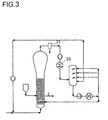
- FIG. 3 shows an exemplary embodiment not according to the invention schematically shown, which essentially that in Figure 1 corresponds to the illustrated example.
- the one leaving the fluid bed reactor Gas becomes - after a fine dust separation if necessary (31), for example with the aid of a cyclone or filter and is via a conventional heat exchanger (33), that is, indirect heat exchanger, the direct cooling device fed as described in Example 1.
- FIG. 4 shows a further preferred exemplary embodiment of the schematically illustrated method according to the invention, which on Modifications described below to those in the previous ones Examples of exemplary embodiments explained.
- the Gas leaving the fluidized bed reactor (1) is fed into the direct cooler out, here the contact apparatus (5) in direct current is operated, which means that both the fluidizing gas and the coolant flow from top to bottom while being intimate get in touch with each other.
- a causes particularly efficient heat and mass transfer.
- the coolant in the contact apparatus in one or more Levels (41) can be distributed and it can also be done using an or the cooling liquid of the individual liquid feeds collected at the respective levels and separately derived, e.g. especially at the level of gas entry where in addition to the cooling of the gas also an extensive Wash out any dust entrained in the reactor can be done.
- the excess coolant in the reactor can be i.e. in different levels (42) below and / or above of the fluidized bed and / or injected at the level of the fluidized bed become.
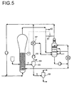
- the exemplary embodiment shown in FIG. 5 also includes a direct cooling device similar to that procedures described in Example 1.
- the direct cooling device or the contact device of the direct cooling (5) is here as Counterflow apparatus with a level nozzle and a sprinkler Pack with catch floor shown.
- one is simplified drawn temperature and start-up control, designed as bypass control (51) around the direct heat exchange.
- the reaction system is shown to the extent that the discharge of the polymer via one or more closure members (3) in a first separation stage (55) arrives.
- the separated gas stream there the so-called carrier gas is from the one prevailing there Pressure that is significantly lower than that of the reactor, for example at 5 to 11 bar, by means of the delivery (56) back to reactor pressure brought.
- the gas flow can then be via an indirect heat exchanger (57) are pre-cooled and the cooled gas to the Internal reactor to be fed back current or that possible condensate in the direct cooling device be initiated.
- the polymer is turned from the deposition (55) into an area low pressure, namely the deposition (58), at 1 to 5 bar continuously or discontinuously with some gas discharged.
- the gas flow released in this separation is subtracted, possibly together with one supplied at (58) Flushing gas stream or the like.
- the polymer leaves the deposition for further processing. If necessary, the deposition (55) also removes an exhaust gas stream at (59), as well as e.g. at (60), if necessary, a further exhaust gas stream can be dissipated.
Landscapes
- Chemical & Material Sciences (AREA)
- Organic Chemistry (AREA)
- Chemical Kinetics & Catalysis (AREA)
- Health & Medical Sciences (AREA)
- Medicinal Chemistry (AREA)
- Polymers & Plastics (AREA)
- Engineering & Computer Science (AREA)
- Combustion & Propulsion (AREA)
- Polymerisation Methods In General (AREA)
Applications Claiming Priority (2)
| Application Number | Priority Date | Filing Date | Title |
|---|---|---|---|
| DE10016625A DE10016625A1 (de) | 2000-04-04 | 2000-04-04 | Gasphasenpolymerisationsverfahren mit Direktkühlsystem |
| DE10016625 | 2000-04-04 |
Publications (2)
| Publication Number | Publication Date |
|---|---|
| EP1142916A1 EP1142916A1 (de) | 2001-10-10 |
| EP1142916B1 true EP1142916B1 (de) | 2004-08-11 |
Family
ID=7637486
Family Applications (1)
| Application Number | Title | Priority Date | Filing Date |
|---|---|---|---|
| EP01108292A Expired - Lifetime EP1142916B1 (de) | 2000-04-04 | 2001-04-02 | Gasphasenpolymerisationsverfahren mit Direktkühlsystem |
Country Status (5)
| Country | Link |
|---|---|
| US (1) | US6472482B1 (cg-RX-API-DMAC7.html) |
| EP (1) | EP1142916B1 (cg-RX-API-DMAC7.html) |
| JP (1) | JP2002020405A (cg-RX-API-DMAC7.html) |
| KR (1) | KR20010095305A (cg-RX-API-DMAC7.html) |
| DE (2) | DE10016625A1 (cg-RX-API-DMAC7.html) |
Families Citing this family (12)
| Publication number | Priority date | Publication date | Assignee | Title |
|---|---|---|---|---|
| EP1651679B1 (en) | 2003-08-07 | 2014-06-18 | Westlake Longview Corporation | Polymerization process and associated apparatus |
| US7253239B2 (en) * | 2004-10-29 | 2007-08-07 | Westlake Longview Corporation | Method for preventing or inhibiting fouling in a gas-phase polyolefin polymerization process |
| CN100460051C (zh) * | 2005-11-17 | 2009-02-11 | 沈阳化工研究院 | 双环流复合式反应装置 |
| EP2222725B1 (en) * | 2007-12-27 | 2019-06-19 | Univation Technologies, LLC | Systems and methods for removing entrained particulates from gas streams |
| KR100968772B1 (ko) * | 2008-01-08 | 2010-07-08 | 대림산업 주식회사 | 올레핀의 중합방법 |
| KR200451727Y1 (ko) * | 2008-06-09 | 2011-01-07 | 이윤우 | 복합식 블라스트 기계 |
| MY190683A (en) | 2014-01-31 | 2022-05-10 | Exxonmobil Chemical Patents Inc | Fluid separation systems and methods |
| KR101969581B1 (ko) | 2016-11-17 | 2019-08-13 | 주식회사 엘지화학 | 올레핀계 단량체의 회수 장치 |
| US11117980B2 (en) | 2017-11-17 | 2021-09-14 | Exxonmobil Chemical Patents Inc. | Polymerization processes |
| CN111748049B (zh) * | 2019-03-27 | 2021-07-16 | 中国石油化工股份有限公司 | 一种烯烃聚合方法及系统 |
| EP3954716B1 (en) * | 2020-08-13 | 2024-01-03 | Borealis AG | Screening assembly and process for screening polymer from an effluent stream at reduced levels of polymer entrainment |
| EP4537919B1 (en) * | 2020-08-13 | 2026-05-13 | Borealis GmbH | Screening assembly and use for screening polymer from an effluent stream at reduced levels of polymer entrainment |
Family Cites Families (14)
| Publication number | Priority date | Publication date | Assignee | Title |
|---|---|---|---|---|
| BE749148A (fr) * | 1970-04-17 | 1970-10-19 | Ici Ltd | Production de copolymeres, |
| IN145649B (cg-RX-API-DMAC7.html) * | 1974-12-16 | 1985-01-05 | Standard Oil Co | |
| JPS582825B2 (ja) | 1977-11-17 | 1983-01-18 | 日本クラウンコルク株式会社 | オレフイン樹脂−金属接着構造物及びその製造方法 |
| US4543399A (en) | 1982-03-24 | 1985-09-24 | Union Carbide Corporation | Fluidized bed reaction systems |
| DZ520A1 (fr) | 1982-03-24 | 2004-09-13 | Union Carbide Corp | Procédé perfectionné pour accroitre le rendement espace temps d'une réaction de polymérisation exothermique en lit fluidisé. |
| US4588750A (en) | 1982-07-02 | 1986-05-13 | Hoffmann-La Roche Inc. | Therapeutic compositions for reducing sebum secretion |
| EP0108710A2 (de) | 1982-10-08 | 1984-05-16 | Ciba-Geigy Ag | Laminate aus Metallplatten und thermoplastischem Material |
| FR2666338B1 (fr) | 1990-08-31 | 1994-04-08 | Bp Chemicals Snc | Procede regule de polymerisation d'olefine en phase gazeuse effectue a l'aide d'un catalyseur a base d'oxyde de chrome. |
| US5352749A (en) | 1992-03-19 | 1994-10-04 | Exxon Chemical Patents, Inc. | Process for polymerizing monomers in fluidized beds |
| DE4218369A1 (de) | 1992-06-04 | 1993-12-09 | Basf Lacke & Farben | Verfahren zur Herstellung eines Metall-Kunststoffolie-Verbundes, nach diesem Verfahren hergestellter Metall-Kunststoffolie-Verbund sowie dessen Verwendung zur Herstellung von Verpackungsbehältern |
| ZA943399B (en) | 1993-05-20 | 1995-11-17 | Bp Chem Int Ltd | Polymerisation process |
| JP3180305B2 (ja) | 1993-08-27 | 2001-06-25 | 宇部興産株式会社 | オレフィンの気相重合法 |
| JPH0949703A (ja) | 1995-08-07 | 1997-02-18 | Mikuni Corp | 磁気式位置センサ |
| EP0824115A1 (en) * | 1996-08-13 | 1998-02-18 | Bp Chemicals S.N.C. | Polymerisation process |
-
2000
- 2000-04-04 DE DE10016625A patent/DE10016625A1/de not_active Withdrawn
-
2001
- 2001-04-02 DE DE50103179T patent/DE50103179D1/de not_active Expired - Lifetime
- 2001-04-02 EP EP01108292A patent/EP1142916B1/de not_active Expired - Lifetime
- 2001-04-04 KR KR1020010017872A patent/KR20010095305A/ko not_active Withdrawn
- 2001-04-04 JP JP2001105686A patent/JP2002020405A/ja active Pending
- 2001-04-04 US US09/822,218 patent/US6472482B1/en not_active Expired - Lifetime
Also Published As
| Publication number | Publication date |
|---|---|
| DE10016625A1 (de) | 2001-10-11 |
| DE50103179D1 (de) | 2004-09-16 |
| EP1142916A1 (de) | 2001-10-10 |
| KR20010095305A (ko) | 2001-11-03 |
| US6472482B1 (en) | 2002-10-29 |
| JP2002020405A (ja) | 2002-01-23 |
Similar Documents
| Publication | Publication Date | Title |
|---|---|---|
| DE60006676T2 (de) | Fluidisierte wirbelschichtpolymerisation | |
| DE69833324T2 (de) | Verfahren zur herstellung von polypropylenlegierungen | |
| DE68919138T2 (de) | Verfahren und Installation zur Polymerisierung von Olefinen im Wirbelbett-Gasphasenreaktor. | |
| DE69828222T2 (de) | Verfahren und Vorrichtung zur Herstellung von Propylen Homo- und Copolymeren | |
| DE69601126T2 (de) | Absorptionsverfahren zur verwerfung von reaktornebenprodukten und gewinnung von monomeren aus abgasströmen von olefinpolymerisationsverfahren | |
| FI112230B (fi) | Polymerointimenetelmä | |
| DE69918432T2 (de) | Kontinuierliche Entfernung von flüchtigen Stoffen in Dispersionspolymerisation | |
| DE69715027T2 (de) | Düse zur zerstäubung einer flüssigkeit in einem wirbelschicht | |
| DE69003120T2 (de) | Verfahren und Apparat für Olefinpolymerisation in der Gasphase in einem Wirbelbettreaktor. | |
| DE69601569T2 (de) | Verfahren und vorrichtung zur gasphasenpolymerisation von alpha-olefinen | |
| DE69821680T2 (de) | Verfahren zur Herstellung von Propylencopolymeren | |
| DE3025051C2 (cg-RX-API-DMAC7.html) | ||
| EP1142916A1 (de) | Gasphasenpolymerisationsverfahren mit Direktkühlsystem | |
| DE102005005506A1 (de) | Verfahren und Vorrichtung zur Polymerisation von Ethylen | |
| DE1745114B2 (de) | Verfahren zur Polymerisation von Äthylen, Propylen und/oder Butylen in der Gasphase | |
| DE2556418A1 (de) | Vorrichtung und verfahren zur dampfphasenpolymerisation von monomeren | |
| DE69119121T2 (de) | Verfahren und Vorrichtung für alpha-Olefinpolymerisation in der Gasphase | |
| DE69717737T2 (de) | Polymerisationsverfahren | |
| DE69825310T2 (de) | Verfahren und vorrichtung zur herstellung von polymeren | |
| DE69102368T2 (de) | Polymerisation in Gasphase. | |
| DE2800907A1 (de) | Verfahren zur polymerisation von aethylen in gasphase | |
| DE102009040424A1 (de) | Vorrichtung und Verfahren zur Herstellung von Polyolefin | |
| US12194398B2 (en) | Screening assembly and process for screening polymer from an effluent stream at reduced levels of polymer entrainment | |
| DE1265418B (de) | Verfahren zur Polymerisation von Olefinen | |
| DE2703167A1 (de) | Selbstabkuehlungsverfahren fuer die herstellung von polymeren und vorrichtung hierfuer |
Legal Events
| Date | Code | Title | Description |
|---|---|---|---|
| PUAI | Public reference made under article 153(3) epc to a published international application that has entered the european phase |
Free format text: ORIGINAL CODE: 0009012 |
|
| AK | Designated contracting states |
Kind code of ref document: A1 Designated state(s): DE FI FR GB IT Kind code of ref document: A1 Designated state(s): AT BE CH CY DE DK ES FI FR GB GR IE IT LI LU MC NL PT SE TR |
|
| AX | Request for extension of the european patent |
Free format text: AL;LT;LV;MK;RO;SI |
|
| 17P | Request for examination filed |
Effective date: 20020223 |
|
| AKX | Designation fees paid |
Free format text: DE FI FR GB IT |
|
| 17Q | First examination report despatched |
Effective date: 20030606 |
|
| RAP1 | Party data changed (applicant data changed or rights of an application transferred) |
Owner name: BASELL POLYOLEFINE GMBH |
|
| GRAP | Despatch of communication of intention to grant a patent |
Free format text: ORIGINAL CODE: EPIDOSNIGR1 |
|
| GRAS | Grant fee paid |
Free format text: ORIGINAL CODE: EPIDOSNIGR3 |
|
| GRAA | (expected) grant |
Free format text: ORIGINAL CODE: 0009210 |
|
| AK | Designated contracting states |
Kind code of ref document: B1 Designated state(s): DE FI FR GB IT |
|
| PG25 | Lapsed in a contracting state [announced via postgrant information from national office to epo] |
Ref country code: FI Free format text: LAPSE BECAUSE OF FAILURE TO SUBMIT A TRANSLATION OF THE DESCRIPTION OR TO PAY THE FEE WITHIN THE PRESCRIBED TIME-LIMIT Effective date: 20040811 Ref country code: GB Free format text: LAPSE BECAUSE OF FAILURE TO SUBMIT A TRANSLATION OF THE DESCRIPTION OR TO PAY THE FEE WITHIN THE PRESCRIBED TIME-LIMIT Effective date: 20040811 |
|
| REG | Reference to a national code |
Ref country code: GB Ref legal event code: FG4D Free format text: NOT ENGLISH |
|
| REF | Corresponds to: |
Ref document number: 50103179 Country of ref document: DE Date of ref document: 20040916 Kind code of ref document: P |
|
| GBV | Gb: ep patent (uk) treated as always having been void in accordance with gb section 77(7)/1977 [no translation filed] |
Effective date: 20040811 |
|
| PLBE | No opposition filed within time limit |
Free format text: ORIGINAL CODE: 0009261 |
|
| STAA | Information on the status of an ep patent application or granted ep patent |
Free format text: STATUS: NO OPPOSITION FILED WITHIN TIME LIMIT |
|
| ET | Fr: translation filed | ||
| RAP2 | Party data changed (patent owner data changed or rights of a patent transferred) |
Owner name: BASELL POLYOLEFINE GMBH |
|
| 26N | No opposition filed |
Effective date: 20050512 |
|
| PGFP | Annual fee paid to national office [announced via postgrant information from national office to epo] |
Ref country code: IT Payment date: 20140414 Year of fee payment: 14 |
|
| REG | Reference to a national code |
Ref country code: FR Ref legal event code: PLFP Year of fee payment: 15 |
|
| PGFP | Annual fee paid to national office [announced via postgrant information from national office to epo] |
Ref country code: DE Payment date: 20150429 Year of fee payment: 15 |
|
| PGFP | Annual fee paid to national office [announced via postgrant information from national office to epo] |
Ref country code: FR Payment date: 20150325 Year of fee payment: 15 |
|
| PG25 | Lapsed in a contracting state [announced via postgrant information from national office to epo] |
Ref country code: IT Free format text: LAPSE BECAUSE OF NON-PAYMENT OF DUE FEES Effective date: 20150402 |
|
| REG | Reference to a national code |
Ref country code: DE Ref legal event code: R119 Ref document number: 50103179 Country of ref document: DE |
|
| REG | Reference to a national code |
Ref country code: FR Ref legal event code: ST Effective date: 20161230 |
|
| PG25 | Lapsed in a contracting state [announced via postgrant information from national office to epo] |
Ref country code: FR Free format text: LAPSE BECAUSE OF NON-PAYMENT OF DUE FEES Effective date: 20160502 Ref country code: DE Free format text: LAPSE BECAUSE OF NON-PAYMENT OF DUE FEES Effective date: 20161101 |