EP1134114A2 - Appui-tête pour sièges de véhicules - Google Patents
Appui-tête pour sièges de véhicules Download PDFInfo
- Publication number
- EP1134114A2 EP1134114A2 EP01105525A EP01105525A EP1134114A2 EP 1134114 A2 EP1134114 A2 EP 1134114A2 EP 01105525 A EP01105525 A EP 01105525A EP 01105525 A EP01105525 A EP 01105525A EP 1134114 A2 EP1134114 A2 EP 1134114A2
- Authority
- EP
- European Patent Office
- Prior art keywords
- cushion
- gear
- holding element
- headrest
- headrest according
- Prior art date
- Legal status (The legal status is an assumption and is not a legal conclusion. Google has not performed a legal analysis and makes no representation as to the accuracy of the status listed.)
- Withdrawn
Links
Images


Classifications
-
- B—PERFORMING OPERATIONS; TRANSPORTING
- B60—VEHICLES IN GENERAL
- B60N—SEATS SPECIALLY ADAPTED FOR VEHICLES; VEHICLE PASSENGER ACCOMMODATION NOT OTHERWISE PROVIDED FOR
- B60N2/00—Seats specially adapted for vehicles; Arrangement or mounting of seats in vehicles
- B60N2/80—Head-rests
- B60N2/806—Head-rests movable or adjustable
- B60N2/865—Head-rests movable or adjustable providing a fore-and-aft movement with respect to the occupant's head
-
- B—PERFORMING OPERATIONS; TRANSPORTING
- B60—VEHICLES IN GENERAL
- B60N—SEATS SPECIALLY ADAPTED FOR VEHICLES; VEHICLE PASSENGER ACCOMMODATION NOT OTHERWISE PROVIDED FOR
- B60N2/00—Seats specially adapted for vehicles; Arrangement or mounting of seats in vehicles
- B60N2/80—Head-rests
- B60N2/806—Head-rests movable or adjustable
- B60N2/809—Head-rests movable or adjustable vertically slidable
-
- B—PERFORMING OPERATIONS; TRANSPORTING
- B60—VEHICLES IN GENERAL
- B60N—SEATS SPECIALLY ADAPTED FOR VEHICLES; VEHICLE PASSENGER ACCOMMODATION NOT OTHERWISE PROVIDED FOR
- B60N2/00—Seats specially adapted for vehicles; Arrangement or mounting of seats in vehicles
- B60N2/80—Head-rests
- B60N2/806—Head-rests movable or adjustable
- B60N2/838—Tiltable
- B60N2/853—Tiltable characterised by their adjusting mechanisms, e.g. electric motors
-
- B—PERFORMING OPERATIONS; TRANSPORTING
- B60—VEHICLES IN GENERAL
- B60N—SEATS SPECIALLY ADAPTED FOR VEHICLES; VEHICLE PASSENGER ACCOMMODATION NOT OTHERWISE PROVIDED FOR
- B60N2/00—Seats specially adapted for vehicles; Arrangement or mounting of seats in vehicles
- B60N2/80—Head-rests
- B60N2/891—Head-rests with the head-rest being comma-shaped in side view
Definitions
- the invention relates to a headrest for a seat cushion and Vehicle seat with backrest according to the preamble of Claim 1.
- the holding element has a bent, U-shaped support bracket on the one with his thighs in two in the backrest integrated guide sleeves is height adjustable and on its crossbar connecting the legs Rotating element of the swivel device carries.
- the rotating element is seated axially displaceable on the U-shaped bracket Upholstery carrier, so that the head cushion in both the Horizontal shifted as well as any horizontal Movement position by one through the crossbar of the bracket extending pivot axis is tiltable. So that can be Head cushion by adjusting the height of the bracket to the Adjust the height of the seat user and by Horizontal shift and tilt adjustment to the head of the Introduce the seated.
- the headrest can be adjusted for height adjustment.
- This interruption of the On the one hand, continuous body support can increase Tension in the back or neck muscles with longer ones Run rides, on the other hand, the headrest offers light weight possible incorrect setting of the altitude is not always the optimal protection in the event of a crash.
- Many headrests will be often adjusted to provide good neck support offer, but too low a headrest leads, in the event of a crash, the risk of a broken neck increases. With the headrest height set correctly on the other hand, the head cushion has no neck support.
- the invention has for its object a headrest to create the kind that is appropriate to the body Has shape and is adjustable in height and inclination so that the back contour of the seated person in any position Training in the neck and back of the head.
- the object of the invention is through the features of Claim 1 solved.
- the headrest according to the invention has the advantage that it is in Height and inclination is always adjustable so that it is always one continuous support of the upper body in the shoulder, Neck and head area realized.
- Headrest offers the greatest safety when it is for the Seated is comfortably adjusted.
- An incorrect setting is reduced to a minimum; because one too low
- the adjusted headrest presses on the back and signals this Seated the need to raise the headrest.
- the swivel device such that the imaginary or fictional axis of rotation when swiveling the The head cushion is always on the backrest mirror ensures the best possible support for the neck muscles.
- the offers headrest according to the invention a good support, since the Impact area is very close to the back of the head and through locking the impact forces directly via the holding element be forwarded to the backrest structure.
- the around the pivot axis of the head cushion, which is outside the Structure of the headrest, always in the area of the Leaning mirror lies, swiveling movement of the Head cushion can be carried out manually or electrically, with the longitudinally concentric circles around the axis of rotation movement of the head cushion in the swivel device with gearbox and gear ratio or with joint mechanism and Backdrop guidance is feasible.
- the head cushion is in lockable in any position. With motor Headrest pivoting can move the headrest position over Map control can be preset automatically, whereby all seat adjustment positions are taken into account. A automatic headrest positioning can also be done using Occupant position detection. The default Position can be corrected by the occupant at any time.
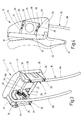
- Fig. 1 in side view Vehicle seat has a seat cushion 11, one on the seat cushion 11 pivoted backrest 12, and one in the Backrest 12 headrest 13 held adjustable in height.
- the front surface of the backrest 12 facing a seated person, the so-called backrest mirror is designated 14.
- the Height adjustment of the headrest 13 is known and in Fig. 1 marked by double arrow 15.
- the only in Fig. 1 schematically indicated headrest 13 consists of a Holding element 16, one arranged on the holding element 16 Cushion carrier 17 and one held on the cushion carrier 17 Head cushion 18 for head support of the seated person.
- the holding element 16 has a U-shaped bracket 19, the two bracket legs in the Backrest structure of the backrest 12 guided and adjustable in height can be locked in any height position.
- the stirrup legs 191 are bent in the upper area and over a cross bar 192 connected with each other.
- a swivel device 20 arranged by means of the cushion carrier 17 with it held head pad 18 by a transverse to the seat depth aligned axis of rotation 21 inclined and thus to the head of the Sedentary can be introduced.
- the swiveling of the Head cushion 18 is shown in FIG. 1 by a double arrow 22 symbolizes.
- the two pivoting end positions of the head cushion 18 are drawn out or drawn in by dashed lines.
- a shape of the headrest that is appropriate for the body Height and inclination is adjustable so that it can be in any position continuous support of the upper body of the seated person, i.e. a shoulder, neck and head support, ensures the head cushion 18 has a one-piece down piece with it
- Upholstery tongue 23 extended beyond the cushion support 17 for neck support and the contour of the front surface 24 of Head cushion 18 and cushion tongue 23 is the course of Formed back of the head and neck.
- Swivel device 20 designed so that the axis of rotation 21 to which swivels the head cushion 18 with the cushion tongue 23, outside the headrest structure is in all possible Height settings of the headrest 13 or the holding element 16 or the bracket 19 always on the backrest mirror 14th
- the upholstery cables 23 pulled down so far that they for the 95% man maximum headrest 13 (Fig. 1A) just up to the top of the backrest 12. At the lowest setting of the headrest 13 for the 5% woman (Fig. 1B) then the cushion tongue 23 is pushed over to the maximum the backrest mirror 14. In both cases, the axis of rotation 21 still in the area of the backrest mirror 14.
- Fig. 2A In the maximum height setting of the headrest 13 for the 95% man (Fig. 2A) creates a gap between the bottom edge the cushion tongue 23 'and the upper edge of the backrest 12.
- Fig. 2A In the maximum height setting of the headrest 13 for the 95% man (Fig. 2A) creates a gap between the bottom edge the cushion tongue 23 'and the upper edge of the backrest 12.
- the axis of rotation 21 of the head cushion 18 lies in two extreme positions on the backrest mirror 14.
- Each of the Swivel devices 20 causes a displacement of the Head cushion 18 on a circular arc section, which is concentric to the imaginary or fictional axis of rotation 21 on the backrest mirror 14 lies.
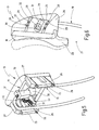
- the Swivel device 20 two in transverse distance from each other arranged sliding members 25 which are fixed to the Holding element 16 and the support bracket 19 are connected.
- each shift link 25 Above and below each shift link 25 is a lower one Slider 26 and an upper slider 27 arranged.
- the sliding members 25 - 27 support each a sliding guide 28 from each other.
- Those facing each other Sliding surfaces 29 of the sliding members 25-27 are Circular arc sections which are concentric with the axis of rotation 21.
- the sliding guides 28 have in the exemplary embodiment in FIG. 3 and 4 sliding bodies 30 inserted between the sliding surfaces 29 on. Instead of sliding bodies 30, rolling bodies can also be used be used or the sliding guides 28 as Dovetail connections are made, the Slide surfaces 29 lie directly on top of one another.
- a ring gear segment 31 attached, which is also coaxial to the axis of rotation 21.
- a gear 32 which is non-rotatable a gear shaft 33 rotatably received in the holding element 16 sits.
- the gear shaft 33 is also seated in a rotationally fixed manner Handwheel 34 which projects laterally on the outside of the holding element 16. If the handwheel 34 is rotated clockwise in FIG. 3, then the gear 32 rolls on the ring gear segment 31 and shifts this, whereby the cushion support 17 with head cushion 18 in the position shown in dashed lines in Fig. 4 is pivoted.
- the pivoting device 20 shown in FIGS. 5 and 6 is correct with the pivoting device 20 described for FIGS. 3 and 4 completely consistent with the difference that the gear shaft 33 not manually using the handwheel, 34 but by motor is rotated.
- the gear shaft 33 not manually using the handwheel, 34 but by motor is rotated.
- Electric motor 35 attached, the via an angular gear 36 Gear shaft 33 rotates.
- the cushion support 17 with head cushion 18th from the representation drawn in FIG. 6 into that in FIG. 6 Position shown in dashed lines transferred.
- head cushion 18 is still one Change made when the cushion tongue 23 ', in Correspondence with the headrest according to FIG. 2, shortened is executed so that the fictitious axis of rotation 21 about which the Head cushion 18 is rotated outside the cushion tongue 23 ' lies, but still with all height adjustments of the Headrest 13 always on the backrest mirror 14.
- pivoting devices 20 can Determining the sliding members 25 on the one hand and the Sliding members 26, 27 on the other hand on the holding element 16 and Upholstery carrier 17 are interchanged.
- the swivel device 20 has two pairs of concentric Axis of rotation 21 arranged, radially spaced from each other Tooth segments 37, 38 whose rows of teeth face each other, and two pairs of each with one of the tooth segments 37, 38 meshing gears 39, 40.
- the total of four Tooth segments 37 and 38 are fastened to the cushion support 17, while the four gears 39 and 40 are rotatable in the Holding element 16 are mounted.
- the two sit with them Tooth segments 37 meshing gears 39 and the two with the Tooth segments 38 meshing gears 40 each on one common gear shaft 41 or 42.
- On the gear shaft 42 there is also a drive gear 43 and a handwheel 44.
- the drive wheel 43 meshes with the gear 39 so that at Turning the gear shaft 42 by means of the handwheel 44 the upper one Gear 40 from gear shaft 41 and lower gear 39 is rotated by the drive wheel 43.
- the toothed segments 37, 38 around the The axis of rotation 21 pivots, whereby the cushion support 17 also moves the head cushion 18 moves in the same direction.
- the pivoting of the head cushion 18 around the imaginary Axis of rotation 21 realized by means of swivel levers, on the one hand on the cushion support 17 and on the other hand on the holding element 16 are articulated.
- the pivot device 20 has a pair of upper ones Pivot lever 45 and a pair of lower pivot lever 46 on the are arranged at a transverse distance from one another. Both Pairs of pivot levers 45, 46 are on the cushion support 17th articulated.
- the lower pair of pivot levers 46 is also on the Holding element 16 and the upper pair of swivel levers 45 on one in Holding element 16 vertically displaceable lever pivot member 47 articulated.
- the lever pivot member 47 has a toothing 48 on and meshes with a drive pinion 49, which together with a handwheel 51 sits on a pinion shaft 50, which in Holding element 16 is rotatably received. If the handwheel 51 in Fig. 9 rotated clockwise, the lever pivot member 47 moved vertically upwards, whereby the cushion support 17th with head cushion 18 via the swivel lever arrangement in the in Fig. 10 swings position shown in dashed lines.
- the in the embodiment of the headrest 13 in Fig. 11 and 12 between holding element 16 and cushion support 17th arranged swivel device 20 in turn has two in Cross-spaced pairs of pivot levers on, which are designed here as angle levers 52, 53.
- the a total of four angle levers 52, 53 are at one end Upholstery support 17 articulated, the articulation of the upper Angle lever 52 is carried out via a slot guide 54.
- the other ends of the angle levers 52, 53 are each at one Threaded sleeve 55 and 56 articulated on a threaded spindle 57 can be screwed.
- the threaded spindle 57 is on Holding element 16 rotatably received and is one Electric motor 58 set in rotation via a gear 59.
- the Threaded spindle 57 has two threaded sections opposite gradients, one each Threaded sleeve 55 or 56 in one of the threaded sections is screwable.
- the head cushion 18 is in his rear end position, as shown in Fig. 12 extended is shown, and will now be the electric motor 58 switched on, the threaded spindle 57 is rotated, and the two threaded sleeves 55, 56 screw on the Threaded spindle 57 in such a way that the distance between the threaded sleeves 55, 56 enlarged.
- the Upholstery carrier 17 pivoted forward, the Articulation points 60 and 61 on the cushion support 17 each on one Move the concentric circular path to the axis of rotation 21.
- the maximum swivel end position is dashed in Fig. 12 drawn.
- the in the embodiment of the headrest 13 shown in FIG. 13 and 14 swivel device 20 has two pairs Lever 62, 63 rotatably connected to one another in a scissor-like manner.
- the levers 62 are at their one lever end on the cushion support 17 and with its other lever end on the holding element 16 articulated.
- the levers 63 are each with a lever end Link guide 64 or 65 with the cushion support 17 or the Holding element 16 connected. Will that in its rear end swivel position standing head pads 18 gripped by hand and pulled forward, it moves through the lever kinematics with link guides 64, 65 around the imaginary pivot axis 21 in the position shown in dashed lines in FIG. 14. Through the The stiffness of the lever kinematics becomes the set one Tilt position of the head cushion 18 in any pivot position held.
Landscapes
- Engineering & Computer Science (AREA)
- Aviation & Aerospace Engineering (AREA)
- Transportation (AREA)
- Mechanical Engineering (AREA)
- Chair Legs, Seat Parts, And Backrests (AREA)
- Seats For Vehicles (AREA)
Applications Claiming Priority (2)
| Application Number | Priority Date | Filing Date | Title |
|---|---|---|---|
| DE10012973A DE10012973B4 (de) | 2000-03-16 | 2000-03-16 | Kopfstütze für einen Fahrzeugsitz |
| DE10012973 | 2000-03-16 |
Publications (2)
| Publication Number | Publication Date |
|---|---|
| EP1134114A2 true EP1134114A2 (fr) | 2001-09-19 |
| EP1134114A3 EP1134114A3 (fr) | 2002-12-11 |
Family
ID=7635059
Family Applications (1)
| Application Number | Title | Priority Date | Filing Date |
|---|---|---|---|
| EP01105525A Withdrawn EP1134114A3 (fr) | 2000-03-16 | 2001-03-06 | Appui-tête pour sièges de véhicules |
Country Status (3)
| Country | Link |
|---|---|
| US (1) | US6511130B2 (fr) |
| EP (1) | EP1134114A3 (fr) |
| DE (1) | DE10012973B4 (fr) |
Cited By (8)
| Publication number | Priority date | Publication date | Assignee | Title |
|---|---|---|---|---|
| WO2005000629A1 (fr) * | 2003-06-27 | 2005-01-06 | In Seon Son | Repose-tete/cou pour un vehicule |
| DE102013000163A1 (de) | 2013-01-09 | 2014-07-10 | Faurecia Autositze Gmbh | Sitzanordnung für ein Fahrzeug |
| DE102013104760B3 (de) * | 2013-05-08 | 2014-07-31 | Faurecia Autositze Gmbh | Fahrzeugsitz, insbesondere für ein Kraftfahrzeug |
| WO2016058581A1 (fr) * | 2014-10-16 | 2016-04-21 | Grammer Ag | Appuie-tête pour siège de véhicule automobile |
| WO2015191709A3 (fr) * | 2014-06-10 | 2016-12-29 | Zodiac Seats Us Llc | Sièges passagers de conception ergonomique monocoques et semi-monocoques |
| CN107009928A (zh) * | 2015-12-21 | 2017-08-04 | 现代岱摩斯 | 自动头枕 |
| US9783304B2 (en) | 2013-04-08 | 2017-10-10 | Singapore Technologies Aerospace Ltd. | Headrest structure, headrest cushion and passenger seat |
| WO2019238735A3 (fr) * | 2018-06-13 | 2020-03-19 | Brose Fahrzeugteile Gmbh & Co. Kg, Coburg | Dossier pour un siège de véhicule et module de tête de dossier |
Families Citing this family (74)
| Publication number | Priority date | Publication date | Assignee | Title |
|---|---|---|---|---|
| DE10047406A1 (de) * | 2000-09-26 | 2002-04-11 | Daimler Chrysler Ag | Kopfstütze |
| JP3757864B2 (ja) * | 2001-12-27 | 2006-03-22 | 日産自動車株式会社 | 車両用ヘッドレスト装置 |
| DE10224061C1 (de) * | 2002-05-31 | 2003-07-24 | Daimler Chrysler Ag | Kopfstütze für einen Fahrzeugsitz |
| NL1020975C2 (nl) * | 2002-07-02 | 2004-01-06 | Whiplash Preventie Systems Hol | Voertuigstoel met in geval van een aanrijding beweegbare hoofdsteun. |
| ITTO20020837A1 (it) * | 2002-09-24 | 2004-03-25 | Gestind Spa | Dispositivo per la movimentazione di un cuscino di un appoggiatesta, particolarmente per sedili di veicoli. |
| US7125077B2 (en) * | 2002-10-25 | 2006-10-24 | L&P Property Management Company | Seat bolster adjustment apparatus and method |
| US7052087B2 (en) * | 2002-12-09 | 2006-05-30 | L&P Property Management Company | Method and apparatus for a scissors ergonomic support |
| US6910740B2 (en) * | 2002-12-09 | 2005-06-28 | Camaco | Articulated headrestraint system |
| TW582241U (en) * | 2002-12-23 | 2004-04-01 | R-Shuen Liau | Improved structure for adjusting height and position of backrest of chair |
| DE10325472A1 (de) * | 2003-06-05 | 2004-12-30 | Keiper Gmbh & Co. Kg | Crashaktive Kopfstütze |
| JP2005013604A (ja) * | 2003-06-27 | 2005-01-20 | Aisin Seiki Co Ltd | アクティブヘッドレスト |
| FR2860461B1 (fr) * | 2003-10-07 | 2005-12-23 | Renault Sa | Ensemble de dossier de siege pour vehicule automobile |
| DE102004030319A1 (de) * | 2004-06-23 | 2006-01-12 | Faurecia Autositze Gmbh & Co. Kg | Kopfstützenanordnung für einen Fahrzeugsitz |
| US7140687B2 (en) * | 2004-11-18 | 2006-11-28 | Fisher Dynamics Corporation | Spring-loaded headrest |
| US7185950B2 (en) * | 2004-12-28 | 2007-03-06 | Fisher Dynamics Corporation | Head restraint system |
| US20060138817A1 (en) * | 2004-12-29 | 2006-06-29 | Gorman Patrick J | Energy absorbing seat recliner assembly |
| DE102005007509B3 (de) * | 2005-02-17 | 2006-10-26 | Johnson Controls Gmbh | Kopfstütze für einen Sitz, insbesondere für ein Kraftfahrzeug und Sitz mit einer erfindungsgemäßen Kopfstütze |
| US20060226686A1 (en) * | 2005-03-22 | 2006-10-12 | Shihong Yu | Spinal protection system for automotive seat |
| US20080217971A1 (en) * | 2005-10-25 | 2008-09-11 | Paluch Zbigniew A | Active Head Restraint |
| US7232187B1 (en) | 2006-03-30 | 2007-06-19 | Ford Global Technologies, Llc | Head restraint for automotive vehicle |
| US20080007105A1 (en) * | 2006-07-06 | 2008-01-10 | Denis Viger | Adjustable headrest assembly |
| US20080030061A1 (en) * | 2006-08-04 | 2008-02-07 | Srinivas Pejathaya | Multi-position adjustment mechanism |
| ES1064266Y (es) * | 2006-12-05 | 2007-05-16 | Batz S Coop | Reposacabezas para asientos de vehiculos automoviles |
| KR100833319B1 (ko) | 2007-01-04 | 2008-05-28 | 주식회사 한일씨엔에프 | 헤드레스트 전후이동장치 |
| DE102007004767A1 (de) * | 2007-01-31 | 2008-08-07 | Bayerische Motoren Werke Aktiengesellschaft | Rückenlehne für einen Fahrzeugsitz mit neigungsverstellbarem Lehnenkopf |
| FR2916423B1 (fr) * | 2007-05-23 | 2010-02-12 | Airbus | Siege avec appui-tete pivotant |
| FR2917344B1 (fr) * | 2007-06-15 | 2009-08-21 | Airbus France Sas | Appui-tete multimodal pour siege de vehicule |
| JP4957416B2 (ja) * | 2007-07-05 | 2012-06-20 | アイシン精機株式会社 | 車両用シート装置 |
| US8033603B2 (en) * | 2007-08-31 | 2011-10-11 | Clifford Bruce Meert | Vehicle seat neck protection device |
| KR101047562B1 (ko) * | 2007-12-18 | 2011-07-07 | 현대자동차주식회사 | 차량용 폴딩 헤드레스트 록킹장치 |
| JP5286861B2 (ja) * | 2008-03-19 | 2013-09-11 | アイシン精機株式会社 | 運動変換駆動装置及びその運動変換駆動装置を備えた車両用シート装置 |
| US8616625B2 (en) * | 2008-05-23 | 2013-12-31 | Johnson Controls Technology Company | Seat headrest |
| KR101054755B1 (ko) * | 2008-08-27 | 2011-08-05 | 기아자동차주식회사 | 시트백 연동형 전후 슬라이딩 헤드레스트 장치 |
| DE102008057792B4 (de) * | 2008-11-17 | 2013-08-14 | Johnson Controls Gmbh | Crashaktive Kopfstütze mit einem sperrenden Druckknopf |
| CN102387937A (zh) * | 2009-04-23 | 2012-03-21 | 李尔公司 | 具有可调节的头部保护装置组件的座椅组件 |
| DE102009020117B4 (de) * | 2009-05-06 | 2013-11-14 | Lear Corp. | Sitzanordnung und verstellbare Kopfstützenanordnung |
| DE102009040069A1 (de) * | 2009-09-04 | 2011-03-24 | Johnson Controls Gmbh | Verstellbare Kopfstütze |
| US9248766B2 (en) * | 2009-10-29 | 2016-02-02 | Toyota Jidosha Kabushiki Kaisha | Headrest stay and active headrest |
| DE102010023403B4 (de) * | 2010-06-11 | 2012-09-27 | Johnson Controls Gmbh | Kopfstütze, insbesondere für ein Kraftfahrzeug |
| DE102010044448B4 (de) * | 2010-09-06 | 2015-05-21 | Johnson Controls Gmbh | In X-Richtung verstellbare Kopfstütze und Arretierungssystem |
| DE102010045736B4 (de) | 2010-09-20 | 2022-06-30 | Adient Luxembourg Holding S.À R.L. | In X-Richtung verstellbare Kopfstütze |
| KR101089888B1 (ko) | 2010-12-02 | 2011-12-05 | 남해현 | 다기능 인체공학 헤드레스트 |
| DE102011004396B4 (de) * | 2011-02-18 | 2016-09-15 | Lear Corporation | Einziehbare Kopfstütze |
| DE102011015348B4 (de) * | 2011-03-28 | 2015-07-16 | Grammer Aktiengesellschaft | Fahrzeugsitz |
| US8801103B2 (en) * | 2011-04-18 | 2014-08-12 | Chrysler Group Llc | Rear vehicle seat automatic head rest system |
| DE102011018611B4 (de) * | 2011-04-21 | 2016-07-28 | Johnson Controls Gmbh | In X-Richtung verstellbare Kopfstütze |
| DE102011108106B4 (de) * | 2011-07-20 | 2016-11-24 | Faurecia Autositze Gmbh | Kraftfahrzeugsitz mit Massagevorrichtung |
| CN103764441B (zh) * | 2011-09-09 | 2016-08-17 | 约翰逊控股公司 | 用于车辆座椅的能调节高度和/或倾斜度的头枕 |
| JP5925575B2 (ja) * | 2012-04-23 | 2016-05-25 | 日本発條株式会社 | ヘッドレスト装置 |
| DE102012213503B3 (de) * | 2012-07-31 | 2013-10-17 | Grammer Ag | Verstellbare Kopfstütze |
| EP2698277B1 (fr) * | 2012-08-13 | 2016-03-23 | Schukra Gerätebau GmbH | Système d'appuie-tête et procédé de réglage d'un appuie-tête |
| KR101428285B1 (ko) * | 2012-12-12 | 2014-08-08 | 현대자동차주식회사 | 리어시트용 헤드레스트의 리클라이닝 장치 |
| JP6107459B2 (ja) * | 2013-06-18 | 2017-04-05 | トヨタ紡織株式会社 | 乗物用シート |
| US9333887B2 (en) * | 2014-06-26 | 2016-05-10 | Ford Global Technologies, Llc | Power articulating headrest assembly |
| KR101576377B1 (ko) * | 2014-07-01 | 2015-12-11 | 현대다이모스(주) | 헤드레스트 리클라이닝 모듈 |
| US9446687B2 (en) * | 2015-01-29 | 2016-09-20 | Ford Global Technologies, Llc | Selectable fixed and rotational seat frame assembly for a vehicle frame |
| US9511696B2 (en) | 2015-05-06 | 2016-12-06 | Daimay North America Automotive, Inc. | Rotatable headrest assembly |
| EP3380359A4 (fr) * | 2015-11-23 | 2019-10-30 | Adient Luxembourg Holding S.à r.l. | Dossier de siège avec pivot d'épaulement motorisé |
| US10399474B2 (en) * | 2016-03-02 | 2019-09-03 | Adient Luxembourg Holding S.a.r.l. | Multi-adjustable head restraint |
| US9889773B2 (en) * | 2016-04-04 | 2018-02-13 | Ford Global Technologies, Llc | Anthropomorphic upper seatback |
| US9950652B2 (en) * | 2016-04-27 | 2018-04-24 | Ford Global Technologies, Llc | Telescoping head restraint |
| JP6711134B2 (ja) * | 2016-05-24 | 2020-06-17 | トヨタ紡織株式会社 | ヘッドレスト |
| US10023090B2 (en) * | 2016-09-07 | 2018-07-17 | Ford Global Technologies, Llc | Vehicle seat with stowable headrest |
| DE102017209880A1 (de) | 2017-06-12 | 2018-12-27 | Sitech Sitztechnik Gmbh | Fahrzeugsitz mit einer multifunktionalen elektrisch ansteuerbaren Nackenstütze |
| US10384566B2 (en) * | 2017-08-25 | 2019-08-20 | Ford Global Technologies, Llc | Vehicle seat assembly |
| GB2567426B (en) | 2017-10-06 | 2020-11-04 | Jaguar Land Rover Ltd | Head restraint assembly |
| CA3093168A1 (fr) | 2018-03-06 | 2019-09-12 | Bombardier Inc. | Appuie-tete destine a un siege |
| CN110228592B (zh) | 2018-03-06 | 2022-11-18 | 庞巴迪公司 | 飞机的乘客座椅 |
| DE102018109611B4 (de) * | 2018-04-10 | 2022-04-21 | Grammer Aktiengesellschaft | Kopfstütze |
| CN108451176A (zh) * | 2018-04-13 | 2018-08-28 | 董京瑶 | 一种贴合学生背部曲线的具有背部按摩功能的学生用座椅 |
| US10493882B1 (en) * | 2018-05-29 | 2019-12-03 | Ford Global Technologies, Llc | Vehicle seatback with thoracic support actuated pillow |
| US10807719B2 (en) * | 2019-02-19 | 2020-10-20 | B/E Aerospace, Inc. | Multi-position adjustable headrest assembly |
| CN111823987A (zh) * | 2020-07-27 | 2020-10-27 | 盐城工学院 | 一种汽车座椅靠枕调节装置 |
| DE102021128756A1 (de) | 2021-11-04 | 2023-05-04 | Bayerische Motoren Werke Aktiengesellschaft | Sitz |
Citations (1)
| Publication number | Priority date | Publication date | Assignee | Title |
|---|---|---|---|---|
| DE4305909C2 (de) | 1993-02-26 | 1997-08-21 | Metallwerk Biebighaeuser Gmbh | Verstellbare Kraftfahrzeug-Kopfstütze |
Family Cites Families (22)
| Publication number | Priority date | Publication date | Assignee | Title |
|---|---|---|---|---|
| DE3404379A1 (de) * | 1984-02-08 | 1985-08-14 | C. Rob. Hammerstein Gmbh, 5650 Solingen | Kopfstuetze eines fahrzeugsitzes mit zwei an der sitzlehne befestigbaren tragholmen |
| US4693515A (en) * | 1986-10-27 | 1987-09-15 | Itt Corporation | Headrest for an automotive vehicle seat |
| US4856848A (en) * | 1988-06-30 | 1989-08-15 | General Motors Corporation | Manual headrest |
| DE3900495A1 (de) * | 1989-01-10 | 1990-07-26 | Bayerische Motoren Werke Ag | Kopfstuetze fuer einen kraftfahrzeugsitz |
| US5181763A (en) * | 1990-09-20 | 1993-01-26 | Ronald P. Dellanno | Apparatus for preventing whiplash |
| JP2587323B2 (ja) * | 1990-12-25 | 1997-03-05 | 小糸工業株式会社 | 座席用ヘッドレスト |
| DE19513777B4 (de) * | 1994-04-13 | 2004-04-15 | Pitencel, Héctor Manuel | Kopfstütze |
| NL9400588A (nl) * | 1994-04-13 | 1995-11-01 | Johannes Theodorus Marie Rasen | Stoel. |
| JP2943051B2 (ja) * | 1995-02-21 | 1999-08-30 | 池田物産株式会社 | 可動ヘッドレスト |
| DE29504287U1 (de) * | 1995-03-13 | 1995-05-11 | Bonke Christoph Dr | Individuell anpaßbare Kopfstütze für Sitze mit Rückenlehne |
| KR0131029B1 (ko) * | 1995-04-06 | 1998-04-21 | 전성원 | 각도조절이 용이한 자동차용 머리받침대 |
| DE19520893A1 (de) * | 1995-06-08 | 1996-12-12 | Fingscheidt Gmbh Friedr | Kopfstützenklappvorrichtung |
| DE19548339C2 (de) * | 1995-12-22 | 1998-05-28 | Daimler Benz Ag | Kopfstütze für einen Fahrzeugsitz |
| DE29601479U1 (de) * | 1996-01-29 | 1996-05-30 | Trw Repa Gmbh | Fahrzeugsitz |
| FR2746065B1 (fr) * | 1996-03-18 | 1998-05-22 | Appui-tete pour siege de vehicule automobile | |
| SE510735C2 (sv) * | 1996-09-06 | 1999-06-21 | Saab Automobile | Fordonsstol försedd med ett nackstöd |
| JP3758275B2 (ja) * | 1997-02-25 | 2006-03-22 | アイシン精機株式会社 | 車両用ヘッドレスト装置 |
| DE19722515C1 (de) * | 1997-05-30 | 1998-09-03 | Faure Bertrand Sitztech Gmbh | Höhenverstellbare Kopfstütze, insbesondere für Kraftfahrzeugsitze |
| US5829838A (en) * | 1997-08-11 | 1998-11-03 | General Motors Corporation | Integral automotive seatback and headrest cushion |
| DE19739131C1 (de) * | 1997-09-06 | 1998-12-10 | Daimler Benz Ag | Kopfstütze für einen Fahrzeugsitz |
| US6074011A (en) * | 1998-03-16 | 2000-06-13 | Johnson Controls Technology Company | Automatic retractable head restraint |
| JPH11262427A (ja) * | 1998-03-18 | 1999-09-28 | Ikeda Bussan Co Ltd | 可動式ヘッドレスト |
-
2000
- 2000-03-16 DE DE10012973A patent/DE10012973B4/de not_active Expired - Fee Related
-
2001
- 2001-03-06 EP EP01105525A patent/EP1134114A3/fr not_active Withdrawn
- 2001-03-16 US US09/809,434 patent/US6511130B2/en not_active Expired - Fee Related
Patent Citations (1)
| Publication number | Priority date | Publication date | Assignee | Title |
|---|---|---|---|---|
| DE4305909C2 (de) | 1993-02-26 | 1997-08-21 | Metallwerk Biebighaeuser Gmbh | Verstellbare Kraftfahrzeug-Kopfstütze |
Cited By (14)
| Publication number | Priority date | Publication date | Assignee | Title |
|---|---|---|---|---|
| WO2005000629A1 (fr) * | 2003-06-27 | 2005-01-06 | In Seon Son | Repose-tete/cou pour un vehicule |
| US9517708B2 (en) | 2013-01-09 | 2016-12-13 | Faurecia Autositze Gmbh | Seat arrangement for a vehicle |
| DE102013000163A1 (de) | 2013-01-09 | 2014-07-10 | Faurecia Autositze Gmbh | Sitzanordnung für ein Fahrzeug |
| WO2014108113A1 (fr) | 2013-01-09 | 2014-07-17 | Faurecia Autositze Gmbh | Dispositif de siège pour véhicule |
| US9783304B2 (en) | 2013-04-08 | 2017-10-10 | Singapore Technologies Aerospace Ltd. | Headrest structure, headrest cushion and passenger seat |
| WO2014180467A1 (fr) | 2013-05-08 | 2014-11-13 | Faurecia Autositze Gmbh | Siège de véhicule, notamment de véhicule automobile |
| DE102013104760B3 (de) * | 2013-05-08 | 2014-07-31 | Faurecia Autositze Gmbh | Fahrzeugsitz, insbesondere für ein Kraftfahrzeug |
| WO2015191709A3 (fr) * | 2014-06-10 | 2016-12-29 | Zodiac Seats Us Llc | Sièges passagers de conception ergonomique monocoques et semi-monocoques |
| US10442330B2 (en) | 2014-06-10 | 2019-10-15 | Safran Seats Usa Llc | Monocoque and semi-monocoque passenger seats with ergonomic design |
| US11654807B2 (en) | 2014-06-10 | 2023-05-23 | Safran Seats Usa Llc | Monocoque and semi-monocoque passenger seats with ergonomic design |
| WO2016058581A1 (fr) * | 2014-10-16 | 2016-04-21 | Grammer Ag | Appuie-tête pour siège de véhicule automobile |
| CN107009928A (zh) * | 2015-12-21 | 2017-08-04 | 现代岱摩斯 | 自动头枕 |
| CN107009928B (zh) * | 2015-12-21 | 2019-05-31 | 现代岱摩斯 | 自动头枕 |
| WO2019238735A3 (fr) * | 2018-06-13 | 2020-03-19 | Brose Fahrzeugteile Gmbh & Co. Kg, Coburg | Dossier pour un siège de véhicule et module de tête de dossier |
Also Published As
| Publication number | Publication date |
|---|---|
| DE10012973B4 (de) | 2004-02-26 |
| US20020043860A1 (en) | 2002-04-18 |
| US6511130B2 (en) | 2003-01-28 |
| DE10012973A1 (de) | 2001-09-27 |
| EP1134114A3 (fr) | 2002-12-11 |
Similar Documents
| Publication | Publication Date | Title |
|---|---|---|
| EP1134114A2 (fr) | Appui-tête pour sièges de véhicules | |
| EP1712410B1 (fr) | Siège de véhicule à dossier deformable | |
| DE19646470B4 (de) | Kraftfahrzeugsitz mit einer Lehne und einem Sitz | |
| DE4009127C2 (de) | Kopfstützenanordnung | |
| DE10226717B4 (de) | Gestell eines Kraftfahrzeugsitzes mit einem Sitzträger und einem Polsterträger | |
| DE102014011884B4 (de) | Fahrzeugsitz mit veränderbarer Rückenlehne | |
| EP0248418A2 (fr) | Siège fonctionnel | |
| DE2626442A1 (de) | Hoehenverstellbarer sitz insbesondere kraftwagensitz | |
| DE19647464A1 (de) | Fahrzeugsitz | |
| DE2736550C2 (fr) | ||
| EP1224093A1 (fr) | Dispositif d'ajustement pour position en hauteur et en longueur et inclinaison d'un siege de vehicule | |
| EP0253222B1 (fr) | Siège de véhicule ayant un coussin de siège ajustable en inclination par réglage de l'arête avant de siège en hauteur | |
| DE19943707A1 (de) | Fahrzeugsitz | |
| DE3617810C2 (fr) | ||
| EP1360085B1 (fr) | Siège, en particulier siège de véhicule, de préférence siège passager d'avion | |
| DE2952064A1 (de) | Sitzanordnung mit einem sitz und einer in ihrer neugung verstellbaren lehne, insbesondere in einem fahrzeug | |
| EP1048510B1 (fr) | Banquette pour véhicules automobiles | |
| EP1608530B1 (fr) | Appui-tete, utilise en particulier pour un siege de vehicule | |
| DE19738200C2 (de) | Fahrzeugsitz mit Kopfstütze | |
| DE19602909A1 (de) | Kopfstütze für Fahrzeugsitze | |
| EP0518130B1 (fr) | Siège de véhicule à ajustement en hauteur du siège et du dossier | |
| DE19920216B4 (de) | Kraftfahrzeugsitz | |
| DE3125312A1 (de) | Rueckenlehne fuer einen zahnaerztlichen patientenstuhl | |
| DE19617401C2 (de) | Fahrzeugsitz mit Sitzneigungsverstellung | |
| DE19501521A1 (de) | Verstellbarer Fahrzeugsitz |
Legal Events
| Date | Code | Title | Description |
|---|---|---|---|
| PUAI | Public reference made under article 153(3) epc to a published international application that has entered the european phase |
Free format text: ORIGINAL CODE: 0009012 |
|
| AK | Designated contracting states |
Kind code of ref document: A2 Designated state(s): AT BE CH CY DE DK ES FI FR GB GR IE IT LI LU MC NL PT SE TR |
|
| AX | Request for extension of the european patent |
Free format text: AL;LT;LV;MK;RO;SI |
|
| PUAL | Search report despatched |
Free format text: ORIGINAL CODE: 0009013 |
|
| AK | Designated contracting states |
Kind code of ref document: A3 Designated state(s): AT BE CH CY DE DK ES FI FR GB GR IE IT LI LU MC NL PT SE TR |
|
| AX | Request for extension of the european patent |
Free format text: AL;LT;LV;MK;RO;SI |
|
| 17P | Request for examination filed |
Effective date: 20021129 |
|
| AKX | Designation fees paid |
Designated state(s): DE FR GB IT |
|
| GRAP | Despatch of communication of intention to grant a patent |
Free format text: ORIGINAL CODE: EPIDOSNIGR1 |
|
| STAA | Information on the status of an ep patent application or granted ep patent |
Free format text: STATUS: THE APPLICATION HAS BEEN WITHDRAWN |
|
| 18W | Application withdrawn |
Effective date: 20070120 |