EP1132264A2 - Vorrichtung für einen Gurthöhenversteller eines Sicherheitsgurtsystems - Google Patents
Vorrichtung für einen Gurthöhenversteller eines Sicherheitsgurtsystems Download PDFInfo
- Publication number
- EP1132264A2 EP1132264A2 EP01101029A EP01101029A EP1132264A2 EP 1132264 A2 EP1132264 A2 EP 1132264A2 EP 01101029 A EP01101029 A EP 01101029A EP 01101029 A EP01101029 A EP 01101029A EP 1132264 A2 EP1132264 A2 EP 1132264A2
- Authority
- EP
- European Patent Office
- Prior art keywords
- deformation elements
- pillar
- plate
- belt system
- rail
- Prior art date
- Legal status (The legal status is an assumption and is not a legal conclusion. Google has not performed a legal analysis and makes no representation as to the accuracy of the status listed.)
- Granted
Links
Images


Classifications
-
- B—PERFORMING OPERATIONS; TRANSPORTING
- B60—VEHICLES IN GENERAL
- B60R—VEHICLES, VEHICLE FITTINGS, OR VEHICLE PARTS, NOT OTHERWISE PROVIDED FOR
- B60R21/00—Arrangements or fittings on vehicles for protecting or preventing injuries to occupants or pedestrians in case of accidents or other traffic risks
- B60R21/02—Occupant safety arrangements or fittings, e.g. crash pads
- B60R21/055—Padded or energy-absorbing fittings, e.g. seat belt anchors
-
- B—PERFORMING OPERATIONS; TRANSPORTING
- B60—VEHICLES IN GENERAL
- B60R—VEHICLES, VEHICLE FITTINGS, OR VEHICLE PARTS, NOT OTHERWISE PROVIDED FOR
- B60R22/00—Safety belts or body harnesses in vehicles
- B60R22/18—Anchoring devices
- B60R22/20—Anchoring devices adjustable in position, e.g. in height
- B60R22/201—Anchoring devices adjustable in position, e.g. in height with the belt anchor connected to a slider movable in a vehicle-mounted track
Definitions
- the invention relates to a device for a belt height adjuster Seat belt system according to the preamble of claim 1.
- U1 a device for a belt height adjuster of a seat belt system in a motor vehicle is known, which is attached to a pillar of a vehicle body via a locking rail with the interposition of a deformation element. Furthermore, from DE 196 51 092 A1 a seat belt device for a vehicle is known, which forms an anchor rail for the seat belt device, which is connected to a column wall of the vehicle body by means of a screw and the screws are based in an impact absorption element. In an impact situation, this element deforms and absorbs impact energy plastically.
- the object of the invention is to provide a device for a belt height adjuster To create a seat belt system that has an energy absorbing effect in the event of a head impact and leaves the vehicle pillar largely undamaged.
- the main advantages achieved with the invention are that conical executed deformation elements in the manner between a locking rail Device or a support plate of the device and a column wall arranged are, so that in the event of a head impact, the deformation elements plastically Avoid damage to the vehicle pillar.
- the locking rail is attached to the carrier plate by means of screws that are attached to the Fastening plate are connected so that in the event of a head impact the fastening plate, which is in an assembled operating position against the column wall a head impact into the column moves away from the column wall.
- the deformation element when the support plate is omitted be attached directly to the locking rail or be supported on it, wherein in any case, the connecting screws push through the deformation element.
- the conical deformation element is included trimmed its small diameter of the locking rail or the support plate and the larger diameter is supported on the column wall.
- spring systems can also be used existing deformation elements are used, in particular disc springs or compression springs are used.
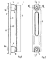
- a device 1 for a belt height adjuster essentially comprises a locking rail 2, a carrier plate 3, deformation elements 4, 5 and a mounting plate 6.
- the connecting unit is attached to a column wall 11 by means of connecting screws 9, 10 an A and / or B pillar of the vehicle body.
- the screws 9, 10 are firmly connected to the mounting plate 6 Weld nuts 9a, 10a set.
- the mounting plate 6 moves into a space 12 of the column S of the area F1 away.
- the locking rail 2 is on the carrier plate 3 attached.
- the Carrier plate 3 and the deformation elements 5, 6 are directly on the locking rail 2 and supported on the column wall 11.
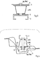
- the conical deformation elements 4, 5 are small with their Diameter of the locking rail 2 or, according to a further embodiment of the carrier plate 3 trimmed, the larger diameter of the deformation elements 4, 5 on the Column wall 11 or against the surface F2 of the column wall 11.
- Deformation elements in the form of spring systems are also conceivable, for example Disc springs or compression springs, which is not shown in detail.
- the deformation elements can not only be arranged at the end of the locking rail 2 or the carrier plate 3, but also extend over the entire length, with more than two deformation elements possible are.
- the conical deformation element 4, 5 by means of a flanging or crimping in a hole in the locking rail 2 or the support plate 3 are held so that a replaceable unit can be produced.
Landscapes
- Engineering & Computer Science (AREA)
- Mechanical Engineering (AREA)
- Automotive Seat Belt Assembly (AREA)
- Devices For Conveying Motion By Means Of Endless Flexible Members (AREA)
Abstract
Description
DE 44 05 106 A1 eine Verankerung für einen Sicherheitsgurt bekannt, wobei ein Aufprallabsorptionsteil verwendet wird, das mit einem Ende an einem Rahmen und mit seinem anderen Ende an der Fahrzeugkarosserie gesichert ist und welches durch eine auf den Rahmen einwirkende Belastung deformierbar ist.
- Fig. 1
- eine erste Ausführung einer Vorrichtung für einen Gurthöhenversteller in einem Vertikalschnitt nach der Linie I-I der Fig. 2 mit Rastschiene, Trägerplatte und kegelförmigen Deformationselementen sowie mit einer Befestigungsplatte,
- Fig. 2
- eine Draufsicht auf die Trägerplatte mit Deformationselementen,
- Fig. 3
- einen Schnitt nach der Linie III-III der Fig. 2 in vergrößerter Darstellung,
- Fig. 4
- einen Horizontalschnitt durch eine Fahrzeugsäule mit eingesetzter Vorrichtung in einer Betriebsstellung und in einer Stellung nach einem Kopfaufprall,
- Fig. 5
- eine schaubildliche Darstellung einer weiteren Ausführung der Vorrichtung mit Rastschiene, Deformationselement und Befestigungsplatte, bei Entfall der Trägerplatte und
- Fig. 6
- die Vorrichtung im Vertikalschnitt gemäß der Fig. 4 und 5 mit Rastschiene, Deformationselementen und Befestigungsplatte.
Claims (6)
- Vorrichtung für einen Gurthöhenversteller eines Sicherheitsgurtsystems, der in einer Säule eines Fahrzeugs angeordnet ist und zwischen einer Rastschiene des Gurtsystems und der Säule mindestens ein Deformationselement angeordnet ist, dadurch gekennzeichnet, daß die Rastschiene (2) mit einer Trägerplatte (3) verbunden ist und diese unter Zwischenschaltung von beabstandet zueinander angeordneten kegelförmig ausgebildeten Deformationselementen (4, 5) über eine Befestigungsplatte (6) an einer Fläche (F2) einer Säulenwand (11) des Fahrzeugaufbaus abgestützt gehalten wird und die Befestigungsplatte (6) in einer montierten Betriebsstellung (I) anliegend an einer zur Fläche (F2) der Säulenwand (11) abgekehrten Fläche (F1) und in einer Stellung (II) nach einem Kopfaufprall losgelöst von dieser Fläche F1 in einem Freiraum (12) der Säule (S) hineinwandernd angeordnet ist.
- Vorrichtung nach Anspruch 1, dadurch gekennzeichnet, daß die jeweils zwischen der Trägerplatte (3) und der Säulenwand (11) angeordneten Deformationselemente (4, 5) von Befestigungsschrauben (9, 10) durchsetzt sind, und an Schweißmuttern (9a, 10a) der Befestigungplatte (6) gehalten werden.
- Vorrichtung nach Anspruch 1, dadurch gekennzeichnet, daß zwischen der Rastschiene (2) und der Säulenwand (11), bei Entfall der Trägerplatte (3), die Deformationselemente (4, 5) angeordnet sind.
- Vorrichtung nach den Ansprüchen 1, 2 oder 3, dadurch gekennzeichnet, daß die Deformationselemente (4, 5) mit ihrem kleineren Durchmesser der Trägerplatte (3) oder der Rastschiene (2) und mit ihrem größeren Durchmesser der Säulenwand (11) bzw. der Fläche (F2) zugerichtet sind.
- Vorrichtung nach den Ansprüchen 1, 2, 3 oder 4, dadurch gekennzeichnet, daß die Deformationselemente (4, 5) mit der Trägerplatte (3) oder der Rastschiene (2) mittels eines im Grund des Elements vorgesehenen Umbördelung in einer Bohrung der Trägerplatte (3) bzw. der Rastschiene (2) gehalten sind.
- Vorrichtung für einen Gurthöhenversteller eines Sicherheitsgurtsystems, der in einer Säule eines Fahrzeugs angeordnet ist, und zwischen einer Rastschiene des Gurtsystems und der Säule mindestens ein Deformationselement angeordnet ist, dadurch gekennzeichnet, daß die Deformationselemente zwischen der Rastschiene 2 oder der Trägerplatte 3 und der Säulenwand 11 aus Druck―und/oder Tellerfeder bestehen.
Applications Claiming Priority (2)
| Application Number | Priority Date | Filing Date | Title |
|---|---|---|---|
| DE10011902 | 2000-03-11 | ||
| DE10011902A DE10011902C1 (de) | 2000-03-11 | 2000-03-11 | Vorrichtung für einen Gurthöhenversteller eines Sicherheitsgurtsystems |
Publications (3)
| Publication Number | Publication Date |
|---|---|
| EP1132264A2 true EP1132264A2 (de) | 2001-09-12 |
| EP1132264A3 EP1132264A3 (de) | 2002-05-15 |
| EP1132264B1 EP1132264B1 (de) | 2004-04-07 |
Family
ID=7634351
Family Applications (1)
| Application Number | Title | Priority Date | Filing Date |
|---|---|---|---|
| EP01101029A Expired - Lifetime EP1132264B1 (de) | 2000-03-11 | 2001-01-18 | Vorrichtung für einen Gurthöhenversteller eines Sicherheitsgurtsystems |
Country Status (6)
| Country | Link |
|---|---|
| US (1) | US6431603B2 (de) |
| EP (1) | EP1132264B1 (de) |
| JP (1) | JP2001270421A (de) |
| AT (1) | ATE263692T1 (de) |
| DE (2) | DE10011902C1 (de) |
| ES (1) | ES2214348T3 (de) |
Cited By (1)
| Publication number | Priority date | Publication date | Assignee | Title |
|---|---|---|---|---|
| EP1559619A1 (de) * | 2004-01-27 | 2005-08-03 | Dr.Ing. h.c.F. Porsche Aktiengesellschaft | Vorrichtung zu stufenweisen Höhenverstellung eines Halte- oder Umlenkbeschlages eines Sicherheitsgurtes an einem hohlen Karosserieteil eines Kraftfahrzeugs |
Families Citing this family (4)
| Publication number | Priority date | Publication date | Assignee | Title |
|---|---|---|---|---|
| DE102007058398A1 (de) * | 2007-12-03 | 2009-06-04 | Key Plastics Lennestadt Gmbh & Co. Kg | Höhenversteller für einen Fahrzeugsicherheitsgurt |
| CN101434228B (zh) * | 2008-12-19 | 2011-07-13 | 奇瑞汽车股份有限公司 | 汽车安全带固定装置 |
| DE102009035284B4 (de) * | 2009-07-30 | 2021-05-12 | Dr. Ing. H.C. F. Porsche Aktiengesellschaft | Kraftfahrzeug mit einer Tragstruktur |
| US11014528B2 (en) * | 2019-04-19 | 2021-05-25 | Toyota Motor Engineering & Manufacturing North America, Inc. | Energy absorption for D-ring attachment bracket |
Citations (3)
| Publication number | Priority date | Publication date | Assignee | Title |
|---|---|---|---|---|
| DE4405106A1 (de) | 1993-02-17 | 1994-08-18 | Honda Motor Co Ltd | Verankerung für einen Sicherheitsgurt |
| DE29519483U1 (de) | 1995-12-08 | 1996-03-21 | HS Technik und Design Technische Entwicklungen GmbH, 82234 Weßling | Vorrichtung zum Stützen eines Sicherheitsgurtbandes in einem Kraftfahrzeug |
| DE19651092A1 (de) | 1995-12-27 | 1997-07-03 | Honda Motor Co Ltd | Sicherheitsgurtvorrichtung für ein Fahrzeug |
Family Cites Families (13)
| Publication number | Priority date | Publication date | Assignee | Title |
|---|---|---|---|---|
| GB1583553A (en) * | 1976-11-04 | 1981-01-28 | Kangol Magnet Ltd | Seat belt anchorage assemblies |
| US5529344A (en) * | 1993-11-30 | 1996-06-25 | Toyota Jidosha Kabushiki Kaisha | Seat belt device for automobile |
| JP2940434B2 (ja) * | 1995-05-29 | 1999-08-25 | トヨタ自動車株式会社 | 車両用シートベルト装置の衝突エネルギ吸収構造 |
| JP3519184B2 (ja) * | 1995-09-13 | 2004-04-12 | 株式会社東海理化電機製作所 | ショルダアンカ構造 |
| JP2758870B2 (ja) * | 1995-11-20 | 1998-05-28 | 株式会社東海理化電機製作所 | ショルダアンカ構造 |
| US5836613A (en) * | 1996-01-29 | 1998-11-17 | Nissan Motor Co., Ltd. | Car body structure |
| DE19603367A1 (de) * | 1996-01-31 | 1997-08-07 | Albert Griesemer | Vorrichtung zur stufenweisen Höhenverstellung eines End- oder Umlenkbeschlages für einen Sicherheitsgurt |
| JP3362598B2 (ja) * | 1996-04-12 | 2003-01-07 | トヨタ自動車株式会社 | 自動車の車体上部のエネルギ吸収構造 |
| US6007100A (en) * | 1997-01-27 | 1999-12-28 | Trw Vehicle Safety Systems Inc. | Apparatus for protecting a vehicle occupant's head from an impact |
| JPH10217905A (ja) * | 1997-01-31 | 1998-08-18 | Suzuki Motor Corp | シートベルトアジャスターの取付構造 |
| DE29709121U1 (de) * | 1997-05-23 | 1997-09-25 | Trw Occupant Restraint Systems Gmbh, 73551 Alfdorf | Höhenversteller für einen Umlenkbeschlag eines Fahrzeug-Sicherheitsgurtes |
| DE19731806A1 (de) * | 1997-07-24 | 1999-01-28 | Bayerische Motoren Werke Ag | Aufprallschutz für den Umlenkbeschlag eines Sicherheitsgurtes |
| US6032982A (en) * | 1997-11-04 | 2000-03-07 | Chrysler Corporation | Energy absorbing B-pillar seat belt mounting arrangement |
-
2000
- 2000-03-11 DE DE10011902A patent/DE10011902C1/de not_active Expired - Fee Related
-
2001
- 2001-01-18 DE DE50101880T patent/DE50101880D1/de not_active Expired - Lifetime
- 2001-01-18 ES ES01101029T patent/ES2214348T3/es not_active Expired - Lifetime
- 2001-01-18 EP EP01101029A patent/EP1132264B1/de not_active Expired - Lifetime
- 2001-01-18 AT AT01101029T patent/ATE263692T1/de not_active IP Right Cessation
- 2001-03-09 JP JP2001066833A patent/JP2001270421A/ja active Pending
- 2001-03-09 US US09/801,657 patent/US6431603B2/en not_active Expired - Fee Related
Patent Citations (3)
| Publication number | Priority date | Publication date | Assignee | Title |
|---|---|---|---|---|
| DE4405106A1 (de) | 1993-02-17 | 1994-08-18 | Honda Motor Co Ltd | Verankerung für einen Sicherheitsgurt |
| DE29519483U1 (de) | 1995-12-08 | 1996-03-21 | HS Technik und Design Technische Entwicklungen GmbH, 82234 Weßling | Vorrichtung zum Stützen eines Sicherheitsgurtbandes in einem Kraftfahrzeug |
| DE19651092A1 (de) | 1995-12-27 | 1997-07-03 | Honda Motor Co Ltd | Sicherheitsgurtvorrichtung für ein Fahrzeug |
Cited By (1)
| Publication number | Priority date | Publication date | Assignee | Title |
|---|---|---|---|---|
| EP1559619A1 (de) * | 2004-01-27 | 2005-08-03 | Dr.Ing. h.c.F. Porsche Aktiengesellschaft | Vorrichtung zu stufenweisen Höhenverstellung eines Halte- oder Umlenkbeschlages eines Sicherheitsgurtes an einem hohlen Karosserieteil eines Kraftfahrzeugs |
Also Published As
| Publication number | Publication date |
|---|---|
| US20010026067A1 (en) | 2001-10-04 |
| DE50101880D1 (de) | 2004-05-13 |
| DE10011902C1 (de) | 2001-08-09 |
| JP2001270421A (ja) | 2001-10-02 |
| ES2214348T3 (es) | 2004-09-16 |
| EP1132264A3 (de) | 2002-05-15 |
| ATE263692T1 (de) | 2004-04-15 |
| US6431603B2 (en) | 2002-08-13 |
| EP1132264B1 (de) | 2004-04-07 |
Similar Documents
| Publication | Publication Date | Title |
|---|---|---|
| EP1701861B1 (de) | Antrieb einer sitzverstelleinrichtung für kraftfahrzeuge | |
| DE102007042285A1 (de) | Fahrzeugsitz und Montageverfahren | |
| DE19745016C2 (de) | Umlenkbeschlag für Sicherheitsgurte von Fahrzeugen, insbesondere Kraftfahrzeugen | |
| EP2730456B1 (de) | Antrieb einer Sitzverstelleinrichtung für Kraftfahrzeuge | |
| WO2012076006A9 (de) | Vorrichtung zur befestigung von tür- oder klappenscharnieren oder anderen elementen an den türen oder klappen oder an der karosserie von kraftfahrzeugen | |
| EP1251038A2 (de) | Frontmodul mit Montageträger für ein Kraftfahrzeug | |
| EP1565357B1 (de) | Befestigungsanordnung für einen gurtaufroller | |
| DE4405904C1 (de) | Crashgünstige Aggregatlagerung | |
| DE3842351A1 (de) | Verfahren und befestigung zum verbinden vibrierender gegenstaende | |
| DE102009051561A1 (de) | Befestigungselement für einen Dachgepäckträger | |
| DE10011902C1 (de) | Vorrichtung für einen Gurthöhenversteller eines Sicherheitsgurtsystems | |
| EP1132266B1 (de) | Gurthöhenversteller eines Sicherheitsgurtsystems | |
| WO2015078957A1 (de) | Gassackabdeckung und verfahren zu ihrer herstellung | |
| DE102004056430B3 (de) | Manuell längsverstellbarer Kraftfahrzeugsitz | |
| DE60012467T2 (de) | Filterschliessblech für Kraftfahrzeug | |
| EP1132265B1 (de) | Vorrichtung für einen Gurthöhenversteller eines Sicherheitsgurtsystems | |
| EP1168135B1 (de) | Aufnahmevorrichtung für Pedale eines Kraftfahrzeugs | |
| EP1125789B1 (de) | Adapter für einen Dachhaltegriff eines Kfz | |
| DE202009014883U1 (de) | An einem Anhänger befestigbare Kurbelstütze | |
| DE102006005642A1 (de) | Gassackmodul zum Einbau in das Lenkrad eines Kraftfahrzeugs | |
| DE102021129860A1 (de) | Fahrzeugsitz für einen Kraftwagen mit einer Deformationseinrichtung | |
| DE10023403C2 (de) | Befestigungsvorrichtung für Trenneinrichtungen für Fahrzeuginnenräume | |
| DE102022122056B3 (de) | Lenkrad mit einem Airbagmodul | |
| DE102018123538A1 (de) | Verstellbare Lenksäule | |
| DE10249237A1 (de) | Sitzanordnung eines Fahrzeuges mit Deformationselement für den Heckaufprall |
Legal Events
| Date | Code | Title | Description |
|---|---|---|---|
| PUAI | Public reference made under article 153(3) epc to a published international application that has entered the european phase |
Free format text: ORIGINAL CODE: 0009012 |
|
| AK | Designated contracting states |
Kind code of ref document: A2 Designated state(s): AT BE CH CY DE DK ES FI FR GB GR IE IT LI LU MC NL PT SE TR |
|
| AX | Request for extension of the european patent |
Free format text: AL;LT;LV;MK;RO;SI |
|
| PUAL | Search report despatched |
Free format text: ORIGINAL CODE: 0009013 |
|
| AK | Designated contracting states |
Kind code of ref document: A3 Designated state(s): AT BE CH CY DE DK ES FI FR GB GR IE IT LI LU MC NL PT SE TR |
|
| AX | Request for extension of the european patent |
Free format text: AL;LT;LV;MK;RO;SI |
|
| RIC1 | Information provided on ipc code assigned before grant |
Free format text: 7B 60R 22/20 A, 7B 60R 21/055 B |
|
| 17P | Request for examination filed |
Effective date: 20021115 |
|
| AKX | Designation fees paid |
Designated state(s): AT BE CH CY DE DK ES FI FR GB GR IE IT LI LU MC NL PT SE TR |
|
| 17Q | First examination report despatched |
Effective date: 20030425 |
|
| GRAP | Despatch of communication of intention to grant a patent |
Free format text: ORIGINAL CODE: EPIDOSNIGR1 |
|
| GRAS | Grant fee paid |
Free format text: ORIGINAL CODE: EPIDOSNIGR3 |
|
| GRAA | (expected) grant |
Free format text: ORIGINAL CODE: 0009210 |
|
| AK | Designated contracting states |
Kind code of ref document: B1 Designated state(s): AT BE CH CY DE DK ES FI FR GB GR IE IT LI LU MC NL PT SE TR |
|
| PG25 | Lapsed in a contracting state [announced via postgrant information from national office to epo] |
Ref country code: NL Free format text: LAPSE BECAUSE OF FAILURE TO SUBMIT A TRANSLATION OF THE DESCRIPTION OR TO PAY THE FEE WITHIN THE PRESCRIBED TIME-LIMIT Effective date: 20040407 Ref country code: TR Free format text: LAPSE BECAUSE OF FAILURE TO SUBMIT A TRANSLATION OF THE DESCRIPTION OR TO PAY THE FEE WITHIN THE PRESCRIBED TIME-LIMIT Effective date: 20040407 Ref country code: IE Free format text: LAPSE BECAUSE OF FAILURE TO SUBMIT A TRANSLATION OF THE DESCRIPTION OR TO PAY THE FEE WITHIN THE PRESCRIBED TIME-LIMIT Effective date: 20040407 Ref country code: FI Free format text: LAPSE BECAUSE OF FAILURE TO SUBMIT A TRANSLATION OF THE DESCRIPTION OR TO PAY THE FEE WITHIN THE PRESCRIBED TIME-LIMIT Effective date: 20040407 |
|
| REG | Reference to a national code |
Ref country code: GB Ref legal event code: FG4D Free format text: NOT ENGLISH |
|
| REG | Reference to a national code |
Ref country code: CH Ref legal event code: EP |
|
| REG | Reference to a national code |
Ref country code: CH Ref legal event code: NV Representative=s name: ISLER & PEDRAZZINI AG |
|
| REF | Corresponds to: |
Ref document number: 50101880 Country of ref document: DE Date of ref document: 20040513 Kind code of ref document: P |
|
| REG | Reference to a national code |
Ref country code: IE Ref legal event code: FG4D Free format text: GERMAN |
|
| PG25 | Lapsed in a contracting state [announced via postgrant information from national office to epo] |
Ref country code: SE Free format text: LAPSE BECAUSE OF FAILURE TO SUBMIT A TRANSLATION OF THE DESCRIPTION OR TO PAY THE FEE WITHIN THE PRESCRIBED TIME-LIMIT Effective date: 20040707 Ref country code: DK Free format text: LAPSE BECAUSE OF FAILURE TO SUBMIT A TRANSLATION OF THE DESCRIPTION OR TO PAY THE FEE WITHIN THE PRESCRIBED TIME-LIMIT Effective date: 20040707 Ref country code: GR Free format text: LAPSE BECAUSE OF FAILURE TO SUBMIT A TRANSLATION OF THE DESCRIPTION OR TO PAY THE FEE WITHIN THE PRESCRIBED TIME-LIMIT Effective date: 20040707 |
|
| REG | Reference to a national code |
Ref country code: ES Ref legal event code: FG2A Ref document number: 2214348 Country of ref document: ES Kind code of ref document: T3 |
|
| GBT | Gb: translation of ep patent filed (gb section 77(6)(a)/1977) |
Effective date: 20040831 |
|
| NLV1 | Nl: lapsed or annulled due to failure to fulfill the requirements of art. 29p and 29m of the patents act | ||
| REG | Reference to a national code |
Ref country code: IE Ref legal event code: FD4D |
|
| ET | Fr: translation filed | ||
| PG25 | Lapsed in a contracting state [announced via postgrant information from national office to epo] |
Ref country code: CY Free format text: LAPSE BECAUSE OF FAILURE TO SUBMIT A TRANSLATION OF THE DESCRIPTION OR TO PAY THE FEE WITHIN THE PRESCRIBED TIME-LIMIT Effective date: 20050118 Ref country code: LU Free format text: LAPSE BECAUSE OF NON-PAYMENT OF DUE FEES Effective date: 20050118 |
|
| PG25 | Lapsed in a contracting state [announced via postgrant information from national office to epo] |
Ref country code: MC Free format text: LAPSE BECAUSE OF NON-PAYMENT OF DUE FEES Effective date: 20050131 Ref country code: BE Free format text: LAPSE BECAUSE OF NON-PAYMENT OF DUE FEES Effective date: 20050131 |
|
| PLBE | No opposition filed within time limit |
Free format text: ORIGINAL CODE: 0009261 |
|
| STAA | Information on the status of an ep patent application or granted ep patent |
Free format text: STATUS: NO OPPOSITION FILED WITHIN TIME LIMIT |
|
| 26N | No opposition filed |
Effective date: 20050110 |
|
| BERE | Be: lapsed |
Owner name: DR.ING. H.C.F. *PORSCHE A.G. Effective date: 20050131 |
|
| PGFP | Annual fee paid to national office [announced via postgrant information from national office to epo] |
Ref country code: AT Payment date: 20070111 Year of fee payment: 7 |
|
| PGFP | Annual fee paid to national office [announced via postgrant information from national office to epo] |
Ref country code: CH Payment date: 20070112 Year of fee payment: 7 |
|
| PGFP | Annual fee paid to national office [announced via postgrant information from national office to epo] |
Ref country code: ES Payment date: 20070130 Year of fee payment: 7 |
|
| REG | Reference to a national code |
Ref country code: CH Ref legal event code: PCAR Free format text: ISLER & PEDRAZZINI AG;POSTFACH 1772;8027 ZUERICH (CH) |
|
| BERE | Be: lapsed |
Owner name: DR.ING. H.C.F. *PORSCHE A.G. Effective date: 20050131 |
|
| PG25 | Lapsed in a contracting state [announced via postgrant information from national office to epo] |
Ref country code: PT Free format text: LAPSE BECAUSE OF NON-PAYMENT OF DUE FEES Effective date: 20040907 |
|
| REG | Reference to a national code |
Ref country code: CH Ref legal event code: PL |
|
| PG25 | Lapsed in a contracting state [announced via postgrant information from national office to epo] |
Ref country code: CH Free format text: LAPSE BECAUSE OF NON-PAYMENT OF DUE FEES Effective date: 20080131 Ref country code: LI Free format text: LAPSE BECAUSE OF NON-PAYMENT OF DUE FEES Effective date: 20080131 |
|
| PG25 | Lapsed in a contracting state [announced via postgrant information from national office to epo] |
Ref country code: AT Free format text: LAPSE BECAUSE OF NON-PAYMENT OF DUE FEES Effective date: 20080118 |
|
| REG | Reference to a national code |
Ref country code: ES Ref legal event code: FD2A Effective date: 20080119 |
|
| REG | Reference to a national code |
Ref country code: FR Ref legal event code: TP |
|
| PG25 | Lapsed in a contracting state [announced via postgrant information from national office to epo] |
Ref country code: ES Free format text: LAPSE BECAUSE OF NON-PAYMENT OF DUE FEES Effective date: 20080119 |
|
| REG | Reference to a national code |
Ref country code: FR Ref legal event code: CD |
|
| REG | Reference to a national code |
Ref country code: FR Ref legal event code: TP |
|
| REG | Reference to a national code |
Ref country code: GB Ref legal event code: 732E Free format text: REGISTERED BETWEEN 20110310 AND 20110316 |
|
| REG | Reference to a national code |
Ref country code: GB Ref legal event code: 732E Free format text: REGISTERED BETWEEN 20110331 AND 20110406 |
|
| PGFP | Annual fee paid to national office [announced via postgrant information from national office to epo] |
Ref country code: FR Payment date: 20110202 Year of fee payment: 11 Ref country code: IT Payment date: 20110126 Year of fee payment: 11 |
|
| PGFP | Annual fee paid to national office [announced via postgrant information from national office to epo] |
Ref country code: GB Payment date: 20110120 Year of fee payment: 11 |
|
| GBPC | Gb: european patent ceased through non-payment of renewal fee |
Effective date: 20120118 |
|
| REG | Reference to a national code |
Ref country code: FR Ref legal event code: ST Effective date: 20120928 |
|
| PG25 | Lapsed in a contracting state [announced via postgrant information from national office to epo] |
Ref country code: GB Free format text: LAPSE BECAUSE OF NON-PAYMENT OF DUE FEES Effective date: 20120118 |
|
| PG25 | Lapsed in a contracting state [announced via postgrant information from national office to epo] |
Ref country code: IT Free format text: LAPSE BECAUSE OF NON-PAYMENT OF DUE FEES Effective date: 20120118 |
|
| PG25 | Lapsed in a contracting state [announced via postgrant information from national office to epo] |
Ref country code: FR Free format text: LAPSE BECAUSE OF NON-PAYMENT OF DUE FEES Effective date: 20120131 |
|
| PGFP | Annual fee paid to national office [announced via postgrant information from national office to epo] |
Ref country code: DE Payment date: 20171211 Year of fee payment: 18 |
|
| REG | Reference to a national code |
Ref country code: DE Ref legal event code: R119 Ref document number: 50101880 Country of ref document: DE |
|
| PG25 | Lapsed in a contracting state [announced via postgrant information from national office to epo] |
Ref country code: DE Free format text: LAPSE BECAUSE OF NON-PAYMENT OF DUE FEES Effective date: 20190801 |