EP1132264A2 - Height adjustment device for a vehicle safety belt system - Google Patents
Height adjustment device for a vehicle safety belt system Download PDFInfo
- Publication number
- EP1132264A2 EP1132264A2 EP01101029A EP01101029A EP1132264A2 EP 1132264 A2 EP1132264 A2 EP 1132264A2 EP 01101029 A EP01101029 A EP 01101029A EP 01101029 A EP01101029 A EP 01101029A EP 1132264 A2 EP1132264 A2 EP 1132264A2
- Authority
- EP
- European Patent Office
- Prior art keywords
- deformation elements
- pillar
- plate
- belt system
- rail
- Prior art date
- Legal status (The legal status is an assumption and is not a legal conclusion. Google has not performed a legal analysis and makes no representation as to the accuracy of the status listed.)
- Granted
Links
Images


Classifications
-
- B—PERFORMING OPERATIONS; TRANSPORTING
- B60—VEHICLES IN GENERAL
- B60R—VEHICLES, VEHICLE FITTINGS, OR VEHICLE PARTS, NOT OTHERWISE PROVIDED FOR
- B60R21/00—Arrangements or fittings on vehicles for protecting or preventing injuries to occupants or pedestrians in case of accidents or other traffic risks
- B60R21/02—Occupant safety arrangements or fittings, e.g. crash pads
- B60R21/055—Padded or energy-absorbing fittings, e.g. seat belt anchors
-
- B—PERFORMING OPERATIONS; TRANSPORTING
- B60—VEHICLES IN GENERAL
- B60R—VEHICLES, VEHICLE FITTINGS, OR VEHICLE PARTS, NOT OTHERWISE PROVIDED FOR
- B60R22/00—Safety belts or body harnesses in vehicles
- B60R22/18—Anchoring devices
- B60R22/20—Anchoring devices adjustable in position, e.g. in height
- B60R22/201—Anchoring devices adjustable in position, e.g. in height with the belt anchor connected to a slider movable in a vehicle-mounted track
Definitions
- the invention relates to a device for a belt height adjuster Seat belt system according to the preamble of claim 1.
- U1 a device for a belt height adjuster of a seat belt system in a motor vehicle is known, which is attached to a pillar of a vehicle body via a locking rail with the interposition of a deformation element. Furthermore, from DE 196 51 092 A1 a seat belt device for a vehicle is known, which forms an anchor rail for the seat belt device, which is connected to a column wall of the vehicle body by means of a screw and the screws are based in an impact absorption element. In an impact situation, this element deforms and absorbs impact energy plastically.
- the object of the invention is to provide a device for a belt height adjuster To create a seat belt system that has an energy absorbing effect in the event of a head impact and leaves the vehicle pillar largely undamaged.
- the main advantages achieved with the invention are that conical executed deformation elements in the manner between a locking rail Device or a support plate of the device and a column wall arranged are, so that in the event of a head impact, the deformation elements plastically Avoid damage to the vehicle pillar.
- the locking rail is attached to the carrier plate by means of screws that are attached to the Fastening plate are connected so that in the event of a head impact the fastening plate, which is in an assembled operating position against the column wall a head impact into the column moves away from the column wall.
- the deformation element when the support plate is omitted be attached directly to the locking rail or be supported on it, wherein in any case, the connecting screws push through the deformation element.
- the conical deformation element is included trimmed its small diameter of the locking rail or the support plate and the larger diameter is supported on the column wall.
- spring systems can also be used existing deformation elements are used, in particular disc springs or compression springs are used.
- a device 1 for a belt height adjuster essentially comprises a locking rail 2, a carrier plate 3, deformation elements 4, 5 and a mounting plate 6.
- the connecting unit is attached to a column wall 11 by means of connecting screws 9, 10 an A and / or B pillar of the vehicle body.
- the screws 9, 10 are firmly connected to the mounting plate 6 Weld nuts 9a, 10a set.
- the mounting plate 6 moves into a space 12 of the column S of the area F1 away.
- the locking rail 2 is on the carrier plate 3 attached.
- the Carrier plate 3 and the deformation elements 5, 6 are directly on the locking rail 2 and supported on the column wall 11.
- the conical deformation elements 4, 5 are small with their Diameter of the locking rail 2 or, according to a further embodiment of the carrier plate 3 trimmed, the larger diameter of the deformation elements 4, 5 on the Column wall 11 or against the surface F2 of the column wall 11.
- Deformation elements in the form of spring systems are also conceivable, for example Disc springs or compression springs, which is not shown in detail.
- the deformation elements can not only be arranged at the end of the locking rail 2 or the carrier plate 3, but also extend over the entire length, with more than two deformation elements possible are.
- the conical deformation element 4, 5 by means of a flanging or crimping in a hole in the locking rail 2 or the support plate 3 are held so that a replaceable unit can be produced.
Abstract
Die Vorrichtung weist zur Energieabsorption bei einem Kopfaufprall zwischen der Rastschiene und/oder einer Trägerplatte und einer Seitenwand der Säule Deformationselemente in Form von kegelförmig ausgebildeten Deformationselementen bzw. von Federsystemes in Form von Teller- oder Druckfedern auf. <IMAGE>For energy absorption in the event of a head impact between the latching rail and / or a carrier plate and a side wall of the column, the device has deformation elements in the form of conically shaped deformation elements or spring systems in the form of plate or compression springs. <IMAGE>
Description
Die Erfindung bezieht sich auf eine Vorrichtung für einen Gurthöhenversteller eines
Sicherheitsgurtsystems nach dem Oberbegriff des Anspruchs 1.The invention relates to a device for a belt height adjuster
Seat belt system according to the preamble of
Aus der DE 295 19 483 U1 ist eine Vorrichtung für einen Gurthöhenversteller eines
Sicherheitsgurtsystems in einem Kraftfahrzeug bekannt, der über eine Rastschiene unter
Zwischenschaltung eines Deformationselements an einer Säule eines Fahrzeugaufbaus
befestigt ist. Ferner ist aus der DE 196 51 092 A1 eine Sicherheitsgurtvorrichtung für
ein Fahrzeug bekannt, die eine Ankerschiene für die Gurtvorrichtung bildet, welche über
eine Schraube mit einer Säulenwand des Fahrzeugaufbaus verbunden ist und die
Schrauben in einem Aufprall-Absorptionselement gründen. Bei einer Aufprallsituation
verformt sich dieses Element und nimmt plastisch Aufprallenergie auf. Des weiteren ist
aus der
DE 44 05 106 A1 eine Verankerung für einen Sicherheitsgurt bekannt, wobei ein
Aufprallabsorptionsteil verwendet wird, das mit einem Ende an einem Rahmen und mit
seinem anderen Ende an der Fahrzeugkarosserie gesichert ist und welches durch eine
auf den Rahmen einwirkende Belastung deformierbar ist.From DE 295 19 483 U1 a device for a belt height adjuster of a seat belt system in a motor vehicle is known, which is attached to a pillar of a vehicle body via a locking rail with the interposition of a deformation element. Furthermore, from DE 196 51 092 A1 a seat belt device for a vehicle is known, which forms an anchor rail for the seat belt device, which is connected to a column wall of the vehicle body by means of a screw and the screws are based in an impact absorption element. In an impact situation, this element deforms and absorbs impact energy plastically. Furthermore, from the
DE 44 05 106 A1 discloses an anchorage for a seat belt, an impact absorption part being used which is secured at one end to a frame and at the other end to the vehicle body and which is deformable by a load acting on the frame.
Aufgabe der Erfindung ist es, eine Vorrichtung für einen Gurthöhenversteller eines Sicherheitsgurtsystems zu schaffen, die bei einem Kopfaufprall energieabsorbierend wirkt und die Fahrzeugsäule weitestgehend unbeschädigt läßt.The object of the invention is to provide a device for a belt height adjuster To create a seat belt system that has an energy absorbing effect in the event of a head impact and leaves the vehicle pillar largely undamaged.
Diese Aufgabe wird erfindungsgemäß durch die Merkmale des Anspruchs 1 gelöst.
Weitere vorteilhafte Merkmale beeinhalten die Unteransprüche.This object is achieved by the features of
Die mit der Erfindung hauptsächlich erzielten Vorteile bestehen darin, daß kegelförmig ausgeführte Deformationselemente in der Weise zwischen einer Rastschiene der Vorrichtung bzw. einer Trägerplatte der Vorrichtung und einer Säulenwand angeordnet sind, so daß bei einem Kopfaufprall sich die Deformationselemente plastisch bei Vermeidung von Beschädigungen an der Fahrzeugsäule verformen können. Die Befestigung der Rastschiene an der Trägerplatte erfolgt über Schrauben, die mit der Befestigungsplatte verbunden sind, so daß bei einem Kopfaufprall die Befestigungsplatte, welche in einer montierten Betriebsstellung anliegend an der Säulenwand ist, sich bei einem Kopfaufprall in die Säule hinein von der Säulenwand weg verschiebt.The main advantages achieved with the invention are that conical executed deformation elements in the manner between a locking rail Device or a support plate of the device and a column wall arranged are, so that in the event of a head impact, the deformation elements plastically Avoid damage to the vehicle pillar. The The locking rail is attached to the carrier plate by means of screws that are attached to the Fastening plate are connected so that in the event of a head impact the fastening plate, which is in an assembled operating position against the column wall a head impact into the column moves away from the column wall.
Da die Deformationselemente in einer Ausführung nur eingeklemmt zwischen der Rastschiene und der Säulenwand gehalten werden, ist ein Auswechseln dieser zusammengedrückten Deformationselemente in einfacher Weise möglich. Nach einer weiteren Ausführung sind die Deformationselemente mit einem Ende in der Rastschiene oder in der Trägerplatte durch eine Umbördelung in einer Bohrung gehalten. In diesem Fall wird die gesamte Einheit Rastschiene und Deformationselement bzw. Trägerplatte und Deformationselement ausgewechselt.Since the deformation elements in one version are only clamped between the Locking rail and the column wall are kept, is an exchange of this compressed deformation elements possible in a simple manner. After a Another version are the deformation elements with one end in the locking rail or held in the carrier plate by flanging in a bore. In this The entire unit becomes the locking rail and deformation element or carrier plate and deformation element replaced.
Nach der Erfindung kann das Deformationselement bei Entfall der Trägerplatte unmittelbar an der Rastschiene befestigt sein oder aber sich an dieser abstützen, wobei in jedem Fall die Verbindungsschrauben das Deformationselement durchsetzen.According to the invention, the deformation element when the support plate is omitted be attached directly to the locking rail or be supported on it, wherein in any case, the connecting screws push through the deformation element.
Damit eine Stauchung bzw. plastische Verformung der Deformationselemente bei einem Kopfaufprall stattfinden kann, ist das kegelförmig ausgeführte Deformationselement mit seinem kleinen Durchmesser der Rastschiene bzw. der Trägerplatte zugerichtet und der größere Durchmesser stützt sich an der Säulenwand ab.So that a compression or plastic deformation of the deformation elements in one Head impact, the conical deformation element is included trimmed its small diameter of the locking rail or the support plate and the larger diameter is supported on the column wall.
Statt der kegelförmigen Deformationselemente können auch aus Federsystemen bestehende Deformationselemente verwendet werden, wobei insbesondere Tellerfedern oder Druckfedern Anwendung finden.Instead of the conical deformation elements, spring systems can also be used existing deformation elements are used, in particular disc springs or compression springs are used.
Ausführungsbeispiele der Erfindung sind in den Zeichnungen dargestellt und werden im folgenden näher beschrieben. Embodiments of the invention are shown in the drawings and are in following described in more detail.
Es zeigen:
- Fig. 1
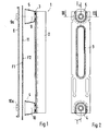
- eine erste Ausführung einer Vorrichtung für einen Gurthöhenversteller in einem Vertikalschnitt nach der Linie I-I der Fig. 2 mit Rastschiene, Trägerplatte und kegelförmigen Deformationselementen sowie mit einer Befestigungsplatte,
- Fig. 2
- eine Draufsicht auf die Trägerplatte mit Deformationselementen,
- Fig. 3
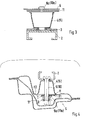
- einen Schnitt nach der Linie III-III der Fig. 2 in vergrößerter Darstellung,
- Fig. 4
- einen Horizontalschnitt durch eine Fahrzeugsäule mit eingesetzter Vorrichtung in einer Betriebsstellung und in einer Stellung nach einem Kopfaufprall,
- Fig. 5
- eine schaubildliche Darstellung einer weiteren Ausführung der Vorrichtung mit Rastschiene, Deformationselement und Befestigungsplatte, bei Entfall der Trägerplatte und
- Fig. 6
- die Vorrichtung im Vertikalschnitt gemäß der Fig. 4 und 5 mit Rastschiene, Deformationselementen und Befestigungsplatte.
- Fig. 1
- 1 shows a first embodiment of a device for a belt height adjuster in a vertical section along the line II of FIG. 2 with locking rail, carrier plate and conical deformation elements and with a fastening plate,
- Fig. 2
- a plan view of the carrier plate with deformation elements,
- Fig. 3
- 3 shows a section along the line III-III of FIG. 2 in an enlarged view,
- Fig. 4
- 2 shows a horizontal section through a vehicle pillar with the device inserted in an operating position and in a position after a head impact,
- Fig. 5
- a perspective view of another embodiment of the device with locking rail, deformation element and mounting plate, in the absence of the support plate and
- Fig. 6
- the device in vertical section according to FIGS. 4 and 5 with locking rail, deformation elements and mounting plate.
Eine Vorrichtung 1 für einen Gurthöhenversteller umfaßt im wesentlichen eine Rastschiene
2, eine Trägerplatte 3, Deformationselemente 4, 5 und eine Befestigungsplatte
6. Über Verbindungsschrauben 9, 10 wird die Baueinheit an einer Säulenwand 11
einer A- und/oder B-Säule des Fahrzeugaufbaus festgesetzt.A
Die Schrauben 9, 10 werden in mit der Befestigungsplatte 6 fest verbundenen
Schweißmuttern 9a, 10a festgelegt. Hierbei liegt in einer montierten Betriebsstellung I die
Befestigungsplatte 6 an der Wandfläche F1 und in einer Stellung II nach einem
Kopfaufprall bewegt sich die Befestigungsplatte 6 in einen Freiraum 12 der Säule S von
der Fläche F1 weg.The
In den Ausführungen gemäß der Fig. 1 bis 4 ist die Rastschiene 2 an der Trägerplatte
3 befestigt. Nach einer weiteren Ausführung gemäß der Fig. 5 und 6 entfällt die
Trägerplatte 3 und die Deformationselemente 5, 6 sind unmittelbar an der Rastschiene 2
und an der Säulenwand 11 abgestützt.In the embodiments according to FIGS. 1 to 4, the
Die kegelförmig ausgeführten Deformationselemente 4, 5 sind mit ihrem kleinen
Durchmesser der Rastschiene 2 oder nach einer weiteren Ausführung der Trägerplatte 3
zugerichtet, wobei der größere Durchmesser der Deformationselemente 4, 5 an der
Säulenwand 11 bzw. an der Fläche F2 der Säulenwand 11 anliegt.The
Denkbar sind auch Deformationselemente in Form von Federsystemen, die beispielsweise
Tellerfedern oder Druckfedern, was nicht näher dargestellt ist. Die Deformationselemente
können nicht nur endseitig der Rastschiene 2 bzw. der Trägerplatte 3 angeordnet sein,
sondern sich auch über die gesamte Länge erstrecken, wobei mehr als zwei Deformationselemente
möglich sind.Deformation elements in the form of spring systems are also conceivable, for example
Disc springs or compression springs, which is not shown in detail. The deformation elements
can not only be arranged at the end of the
Wie in den Figuren 1, 3 und 4 näher gezeigt ist, kann das kegelförmige Deformationselement
4, 5 mittels einer Um- bzw. Einbörtelung in einer Bohrung der Rastschiene 2
oder der Trägerplatte 3 gehalten werden, so daß eine auswechselbare Baueinheit
herstellbar ist.As shown in Figures 1, 3 and 4 in more detail, the
Claims (6)
Applications Claiming Priority (2)
| Application Number | Priority Date | Filing Date | Title |
|---|---|---|---|
| DE10011902 | 2000-03-11 | ||
| DE10011902A DE10011902C1 (en) | 2000-03-11 | 2000-03-11 | Device for a belt height adjuster of a seat belt system |
Publications (3)
| Publication Number | Publication Date |
|---|---|
| EP1132264A2 true EP1132264A2 (en) | 2001-09-12 |
| EP1132264A3 EP1132264A3 (en) | 2002-05-15 |
| EP1132264B1 EP1132264B1 (en) | 2004-04-07 |
Family
ID=7634351
Family Applications (1)
| Application Number | Title | Priority Date | Filing Date |
|---|---|---|---|
| EP01101029A Expired - Lifetime EP1132264B1 (en) | 2000-03-11 | 2001-01-18 | Height adjustment device for a vehicle safety belt system |
Country Status (6)
| Country | Link |
|---|---|
| US (1) | US6431603B2 (en) |
| EP (1) | EP1132264B1 (en) |
| JP (1) | JP2001270421A (en) |
| AT (1) | ATE263692T1 (en) |
| DE (2) | DE10011902C1 (en) |
| ES (1) | ES2214348T3 (en) |
Cited By (1)
| Publication number | Priority date | Publication date | Assignee | Title |
|---|---|---|---|---|
| EP1559619A1 (en) * | 2004-01-27 | 2005-08-03 | Dr.Ing. h.c.F. Porsche Aktiengesellschaft | Device for height adjustment of vehicle seat belt direction reversal fitting |
Families Citing this family (4)
| Publication number | Priority date | Publication date | Assignee | Title |
|---|---|---|---|---|
| DE102007058398A1 (en) * | 2007-12-03 | 2009-06-04 | Key Plastics Lennestadt Gmbh & Co. Kg | Height adjuster for a vehicle seat belt |
| CN101434228B (en) * | 2008-12-19 | 2011-07-13 | 奇瑞汽车股份有限公司 | Fixing device for automobile seat belt |
| DE102009035284B4 (en) * | 2009-07-30 | 2021-05-12 | Dr. Ing. H.C. F. Porsche Aktiengesellschaft | Motor vehicle with a support structure |
| US11014528B2 (en) * | 2019-04-19 | 2021-05-25 | Toyota Motor Engineering & Manufacturing North America, Inc. | Energy absorption for D-ring attachment bracket |
Citations (3)
| Publication number | Priority date | Publication date | Assignee | Title |
|---|---|---|---|---|
| DE4405106A1 (en) | 1993-02-17 | 1994-08-18 | Honda Motor Co Ltd | Anchoring for a seat belt |
| DE29519483U1 (en) | 1995-12-08 | 1996-03-21 | Hs Tech & Design | Device for supporting a seat belt in a motor vehicle |
| DE19651092A1 (en) | 1995-12-27 | 1997-07-03 | Honda Motor Co Ltd | Safety belt device for passenger car |
Family Cites Families (13)
| Publication number | Priority date | Publication date | Assignee | Title |
|---|---|---|---|---|
| GB1583553A (en) * | 1976-11-04 | 1981-01-28 | Kangol Magnet Ltd | Seat belt anchorage assemblies |
| US5529344A (en) * | 1993-11-30 | 1996-06-25 | Toyota Jidosha Kabushiki Kaisha | Seat belt device for automobile |
| JP2940434B2 (en) * | 1995-05-29 | 1999-08-25 | トヨタ自動車株式会社 | Impact energy absorbing structure of vehicle seat belt device |
| JP3519184B2 (en) * | 1995-09-13 | 2004-04-12 | 株式会社東海理化電機製作所 | Shoulder anchor structure |
| JP2758870B2 (en) * | 1995-11-20 | 1998-05-28 | 株式会社東海理化電機製作所 | Shoulder anchor structure |
| US5836613A (en) * | 1996-01-29 | 1998-11-17 | Nissan Motor Co., Ltd. | Car body structure |
| DE19603367A1 (en) * | 1996-01-31 | 1997-08-07 | Albert Griesemer | Stepwise height setting device |
| JP3362598B2 (en) * | 1996-04-12 | 2003-01-07 | トヨタ自動車株式会社 | Energy absorption structure on the upper part of the car body |
| US6007100A (en) * | 1997-01-27 | 1999-12-28 | Trw Vehicle Safety Systems Inc. | Apparatus for protecting a vehicle occupant's head from an impact |
| JPH10217905A (en) * | 1997-01-31 | 1998-08-18 | Suzuki Motor Corp | Mounting structure for seat belt adjuster |
| DE29709121U1 (en) * | 1997-05-23 | 1997-09-25 | Trw Repa Gmbh | Height adjuster for a deflection fitting of a vehicle seat belt |
| DE19731806A1 (en) * | 1997-07-24 | 1999-01-28 | Bayerische Motoren Werke Ag | Impact protection for return fitting of vehicle seat belt |
| US6032982A (en) * | 1997-11-04 | 2000-03-07 | Chrysler Corporation | Energy absorbing B-pillar seat belt mounting arrangement |
-
2000
- 2000-03-11 DE DE10011902A patent/DE10011902C1/en not_active Expired - Fee Related
-
2001
- 2001-01-18 DE DE50101880T patent/DE50101880D1/en not_active Expired - Lifetime
- 2001-01-18 ES ES01101029T patent/ES2214348T3/en not_active Expired - Lifetime
- 2001-01-18 AT AT01101029T patent/ATE263692T1/en not_active IP Right Cessation
- 2001-01-18 EP EP01101029A patent/EP1132264B1/en not_active Expired - Lifetime
- 2001-03-09 JP JP2001066833A patent/JP2001270421A/en active Pending
- 2001-03-09 US US09/801,657 patent/US6431603B2/en not_active Expired - Fee Related
Patent Citations (3)
| Publication number | Priority date | Publication date | Assignee | Title |
|---|---|---|---|---|
| DE4405106A1 (en) | 1993-02-17 | 1994-08-18 | Honda Motor Co Ltd | Anchoring for a seat belt |
| DE29519483U1 (en) | 1995-12-08 | 1996-03-21 | Hs Tech & Design | Device for supporting a seat belt in a motor vehicle |
| DE19651092A1 (en) | 1995-12-27 | 1997-07-03 | Honda Motor Co Ltd | Safety belt device for passenger car |
Cited By (1)
| Publication number | Priority date | Publication date | Assignee | Title |
|---|---|---|---|---|
| EP1559619A1 (en) * | 2004-01-27 | 2005-08-03 | Dr.Ing. h.c.F. Porsche Aktiengesellschaft | Device for height adjustment of vehicle seat belt direction reversal fitting |
Also Published As
| Publication number | Publication date |
|---|---|
| DE10011902C1 (en) | 2001-08-09 |
| US20010026067A1 (en) | 2001-10-04 |
| EP1132264A3 (en) | 2002-05-15 |
| ATE263692T1 (en) | 2004-04-15 |
| US6431603B2 (en) | 2002-08-13 |
| ES2214348T3 (en) | 2004-09-16 |
| EP1132264B1 (en) | 2004-04-07 |
| DE50101880D1 (en) | 2004-05-13 |
| JP2001270421A (en) | 2001-10-02 |
Similar Documents
| Publication | Publication Date | Title |
|---|---|---|
| EP1701861B1 (en) | Drive for adjusting motor vehicle seats | |
| EP2125425B1 (en) | Vehicle seat and assembly method | |
| DE19745016C2 (en) | Deflection fitting for seat belts of vehicles, in particular motor vehicles | |
| WO2012076006A9 (en) | Device for fastening door or flap hinges or other elements to the doors or flaps or to the bodywork of motor vehicles | |
| EP2730456B1 (en) | Drive for a seat adjusting device for motor vehicles | |
| EP2031168B1 (en) | Buffer element | |
| EP1251038A2 (en) | Front module with mounting carrier for a vehicle | |
| EP1565357B1 (en) | Fixing device for a seat belt winder | |
| DE102006005642A1 (en) | Gas bag module for assembly in steering wheel of motor vehicle, has gas bag accommodated in housing and gas generator for filling gas bag | |
| DE10011902C1 (en) | Device for a belt height adjuster of a seat belt system | |
| EP0669244A1 (en) | Support for a mechanical group with good crash behaviour | |
| DE3842351A1 (en) | Process and fastening for connecting vibrating objects | |
| EP1901953B1 (en) | Clamping device for a steering column | |
| DE10011906C1 (en) | Device for a belt height adjuster of a seat belt system | |
| EP2142409B1 (en) | Fastening device for forming an interface between a shell and interior fittings of a rail vehicle | |
| DE10011908C1 (en) | Belt height adjustment device for automobile seatbelt has deformation element at rear of ratchet rail and releasable fixing plate for absorption of head impact energy | |
| DE102004056430B3 (en) | Automobile seat has top set of rails resting in floorpan rails and locked in position by lever clamp | |
| EP1168135B1 (en) | Holding device for motor vehicle pedals | |
| DE60012467T2 (en) | Filter closing plate for motor vehicle | |
| EP1125789B1 (en) | Adapter for a roof assist grip of an automotive vehicles | |
| DE102005037945A1 (en) | Elastic cushion unit for use with seat and floor attachment device in motor vehicle, has radial projection provided at inner contour of hole for gripping installation at shaft of connecting pin, and engaged in grooves of shaft | |
| DE202014001334U1 (en) | Support device for vertical support of a coupling rod with a limiting element | |
| DE10003917B4 (en) | Holding device for a decorative figure of a motor vehicle | |
| DE102021129860A1 (en) | Vehicle seat for a motor vehicle with a deformation device | |
| DE10249237A1 (en) | Fixing arrangement for vehicle seat, comprising rail sliding horizontally with front area and in upwards curve with rear in case of rear impact |
Legal Events
| Date | Code | Title | Description |
|---|---|---|---|
| PUAI | Public reference made under article 153(3) epc to a published international application that has entered the european phase |
Free format text: ORIGINAL CODE: 0009012 |
|
| AK | Designated contracting states |
Kind code of ref document: A2 Designated state(s): AT BE CH CY DE DK ES FI FR GB GR IE IT LI LU MC NL PT SE TR |
|
| AX | Request for extension of the european patent |
Free format text: AL;LT;LV;MK;RO;SI |
|
| PUAL | Search report despatched |
Free format text: ORIGINAL CODE: 0009013 |
|
| AK | Designated contracting states |
Kind code of ref document: A3 Designated state(s): AT BE CH CY DE DK ES FI FR GB GR IE IT LI LU MC NL PT SE TR |
|
| AX | Request for extension of the european patent |
Free format text: AL;LT;LV;MK;RO;SI |
|
| RIC1 | Information provided on ipc code assigned before grant |
Free format text: 7B 60R 22/20 A, 7B 60R 21/055 B |
|
| 17P | Request for examination filed |
Effective date: 20021115 |
|
| AKX | Designation fees paid |
Designated state(s): AT BE CH CY DE DK ES FI FR GB GR IE IT LI LU MC NL PT SE TR |
|
| 17Q | First examination report despatched |
Effective date: 20030425 |
|
| GRAP | Despatch of communication of intention to grant a patent |
Free format text: ORIGINAL CODE: EPIDOSNIGR1 |
|
| GRAS | Grant fee paid |
Free format text: ORIGINAL CODE: EPIDOSNIGR3 |
|
| GRAA | (expected) grant |
Free format text: ORIGINAL CODE: 0009210 |
|
| AK | Designated contracting states |
Kind code of ref document: B1 Designated state(s): AT BE CH CY DE DK ES FI FR GB GR IE IT LI LU MC NL PT SE TR |
|
| PG25 | Lapsed in a contracting state [announced via postgrant information from national office to epo] |
Ref country code: NL Free format text: LAPSE BECAUSE OF FAILURE TO SUBMIT A TRANSLATION OF THE DESCRIPTION OR TO PAY THE FEE WITHIN THE PRESCRIBED TIME-LIMIT Effective date: 20040407 Ref country code: TR Free format text: LAPSE BECAUSE OF FAILURE TO SUBMIT A TRANSLATION OF THE DESCRIPTION OR TO PAY THE FEE WITHIN THE PRESCRIBED TIME-LIMIT Effective date: 20040407 Ref country code: IE Free format text: LAPSE BECAUSE OF FAILURE TO SUBMIT A TRANSLATION OF THE DESCRIPTION OR TO PAY THE FEE WITHIN THE PRESCRIBED TIME-LIMIT Effective date: 20040407 Ref country code: FI Free format text: LAPSE BECAUSE OF FAILURE TO SUBMIT A TRANSLATION OF THE DESCRIPTION OR TO PAY THE FEE WITHIN THE PRESCRIBED TIME-LIMIT Effective date: 20040407 |
|
| REG | Reference to a national code |
Ref country code: GB Ref legal event code: FG4D Free format text: NOT ENGLISH |
|
| REG | Reference to a national code |
Ref country code: CH Ref legal event code: EP |
|
| REG | Reference to a national code |
Ref country code: CH Ref legal event code: NV Representative=s name: ISLER & PEDRAZZINI AG |
|
| REF | Corresponds to: |
Ref document number: 50101880 Country of ref document: DE Date of ref document: 20040513 Kind code of ref document: P |
|
| REG | Reference to a national code |
Ref country code: IE Ref legal event code: FG4D Free format text: GERMAN |
|
| PG25 | Lapsed in a contracting state [announced via postgrant information from national office to epo] |
Ref country code: SE Free format text: LAPSE BECAUSE OF FAILURE TO SUBMIT A TRANSLATION OF THE DESCRIPTION OR TO PAY THE FEE WITHIN THE PRESCRIBED TIME-LIMIT Effective date: 20040707 Ref country code: DK Free format text: LAPSE BECAUSE OF FAILURE TO SUBMIT A TRANSLATION OF THE DESCRIPTION OR TO PAY THE FEE WITHIN THE PRESCRIBED TIME-LIMIT Effective date: 20040707 Ref country code: GR Free format text: LAPSE BECAUSE OF FAILURE TO SUBMIT A TRANSLATION OF THE DESCRIPTION OR TO PAY THE FEE WITHIN THE PRESCRIBED TIME-LIMIT Effective date: 20040707 |
|
| REG | Reference to a national code |
Ref country code: ES Ref legal event code: FG2A Ref document number: 2214348 Country of ref document: ES Kind code of ref document: T3 |
|
| GBT | Gb: translation of ep patent filed (gb section 77(6)(a)/1977) |
Effective date: 20040831 |
|
| NLV1 | Nl: lapsed or annulled due to failure to fulfill the requirements of art. 29p and 29m of the patents act | ||
| REG | Reference to a national code |
Ref country code: IE Ref legal event code: FD4D |
|
| ET | Fr: translation filed | ||
| PG25 | Lapsed in a contracting state [announced via postgrant information from national office to epo] |
Ref country code: CY Free format text: LAPSE BECAUSE OF FAILURE TO SUBMIT A TRANSLATION OF THE DESCRIPTION OR TO PAY THE FEE WITHIN THE PRESCRIBED TIME-LIMIT Effective date: 20050118 Ref country code: LU Free format text: LAPSE BECAUSE OF NON-PAYMENT OF DUE FEES Effective date: 20050118 |
|
| PG25 | Lapsed in a contracting state [announced via postgrant information from national office to epo] |
Ref country code: MC Free format text: LAPSE BECAUSE OF NON-PAYMENT OF DUE FEES Effective date: 20050131 Ref country code: BE Free format text: LAPSE BECAUSE OF NON-PAYMENT OF DUE FEES Effective date: 20050131 |
|
| PLBE | No opposition filed within time limit |
Free format text: ORIGINAL CODE: 0009261 |
|
| STAA | Information on the status of an ep patent application or granted ep patent |
Free format text: STATUS: NO OPPOSITION FILED WITHIN TIME LIMIT |
|
| 26N | No opposition filed |
Effective date: 20050110 |
|
| BERE | Be: lapsed |
Owner name: DR.ING. H.C.F. *PORSCHE A.G. Effective date: 20050131 |
|
| PGFP | Annual fee paid to national office [announced via postgrant information from national office to epo] |
Ref country code: AT Payment date: 20070111 Year of fee payment: 7 |
|
| PGFP | Annual fee paid to national office [announced via postgrant information from national office to epo] |
Ref country code: CH Payment date: 20070112 Year of fee payment: 7 |
|
| PGFP | Annual fee paid to national office [announced via postgrant information from national office to epo] |
Ref country code: ES Payment date: 20070130 Year of fee payment: 7 |
|
| REG | Reference to a national code |
Ref country code: CH Ref legal event code: PCAR Free format text: ISLER & PEDRAZZINI AG;POSTFACH 1772;8027 ZUERICH (CH) |
|
| BERE | Be: lapsed |
Owner name: DR.ING. H.C.F. *PORSCHE A.G. Effective date: 20050131 |
|
| PG25 | Lapsed in a contracting state [announced via postgrant information from national office to epo] |
Ref country code: PT Free format text: LAPSE BECAUSE OF NON-PAYMENT OF DUE FEES Effective date: 20040907 |
|
| REG | Reference to a national code |
Ref country code: CH Ref legal event code: PL |
|
| PG25 | Lapsed in a contracting state [announced via postgrant information from national office to epo] |
Ref country code: CH Free format text: LAPSE BECAUSE OF NON-PAYMENT OF DUE FEES Effective date: 20080131 Ref country code: LI Free format text: LAPSE BECAUSE OF NON-PAYMENT OF DUE FEES Effective date: 20080131 |
|
| PG25 | Lapsed in a contracting state [announced via postgrant information from national office to epo] |
Ref country code: AT Free format text: LAPSE BECAUSE OF NON-PAYMENT OF DUE FEES Effective date: 20080118 |
|
| REG | Reference to a national code |
Ref country code: ES Ref legal event code: FD2A Effective date: 20080119 |
|
| REG | Reference to a national code |
Ref country code: FR Ref legal event code: TP |
|
| PG25 | Lapsed in a contracting state [announced via postgrant information from national office to epo] |
Ref country code: ES Free format text: LAPSE BECAUSE OF NON-PAYMENT OF DUE FEES Effective date: 20080119 |
|
| REG | Reference to a national code |
Ref country code: FR Ref legal event code: CD |
|
| REG | Reference to a national code |
Ref country code: FR Ref legal event code: TP |
|
| REG | Reference to a national code |
Ref country code: GB Ref legal event code: 732E Free format text: REGISTERED BETWEEN 20110310 AND 20110316 |
|
| REG | Reference to a national code |
Ref country code: GB Ref legal event code: 732E Free format text: REGISTERED BETWEEN 20110331 AND 20110406 |
|
| PGFP | Annual fee paid to national office [announced via postgrant information from national office to epo] |
Ref country code: FR Payment date: 20110202 Year of fee payment: 11 Ref country code: IT Payment date: 20110126 Year of fee payment: 11 |
|
| PGFP | Annual fee paid to national office [announced via postgrant information from national office to epo] |
Ref country code: GB Payment date: 20110120 Year of fee payment: 11 |
|
| GBPC | Gb: european patent ceased through non-payment of renewal fee |
Effective date: 20120118 |
|
| REG | Reference to a national code |
Ref country code: FR Ref legal event code: ST Effective date: 20120928 |
|
| PG25 | Lapsed in a contracting state [announced via postgrant information from national office to epo] |
Ref country code: GB Free format text: LAPSE BECAUSE OF NON-PAYMENT OF DUE FEES Effective date: 20120118 |
|
| PG25 | Lapsed in a contracting state [announced via postgrant information from national office to epo] |
Ref country code: IT Free format text: LAPSE BECAUSE OF NON-PAYMENT OF DUE FEES Effective date: 20120118 |
|
| PG25 | Lapsed in a contracting state [announced via postgrant information from national office to epo] |
Ref country code: FR Free format text: LAPSE BECAUSE OF NON-PAYMENT OF DUE FEES Effective date: 20120131 |
|
| PGFP | Annual fee paid to national office [announced via postgrant information from national office to epo] |
Ref country code: DE Payment date: 20171211 Year of fee payment: 18 |
|
| REG | Reference to a national code |
Ref country code: DE Ref legal event code: R119 Ref document number: 50101880 Country of ref document: DE |
|
| PG25 | Lapsed in a contracting state [announced via postgrant information from national office to epo] |
Ref country code: DE Free format text: LAPSE BECAUSE OF NON-PAYMENT OF DUE FEES Effective date: 20190801 |