US6032982A - Energy absorbing B-pillar seat belt mounting arrangement - Google Patents
Energy absorbing B-pillar seat belt mounting arrangement Download PDFInfo
- Publication number
- US6032982A US6032982A US08/963,750 US96375097A US6032982A US 6032982 A US6032982 A US 6032982A US 96375097 A US96375097 A US 96375097A US 6032982 A US6032982 A US 6032982A
- Authority
- US
- United States
- Prior art keywords
- pillar
- seat belt
- mounting arrangement
- belt webbing
- anchorage assembly
- Prior art date
- Legal status (The legal status is an assumption and is not a legal conclusion. Google has not performed a legal analysis and makes no representation as to the accuracy of the status listed.)
- Expired - Lifetime
Links
Images
Classifications
-
- B—PERFORMING OPERATIONS; TRANSPORTING
- B60—VEHICLES IN GENERAL
- B60R—VEHICLES, VEHICLE FITTINGS, OR VEHICLE PARTS, NOT OTHERWISE PROVIDED FOR
- B60R22/00—Safety belts or body harnesses in vehicles
- B60R22/18—Anchoring devices
- B60R22/20—Anchoring devices adjustable in position, e.g. in height
- B60R22/201—Anchoring devices adjustable in position, e.g. in height with the belt anchor connected to a slider movable in a vehicle-mounted track
-
- B—PERFORMING OPERATIONS; TRANSPORTING
- B60—VEHICLES IN GENERAL
- B60R—VEHICLES, VEHICLE FITTINGS, OR VEHICLE PARTS, NOT OTHERWISE PROVIDED FOR
- B60R21/00—Arrangements or fittings on vehicles for protecting or preventing injuries to occupants or pedestrians in case of accidents or other traffic risks
- B60R21/02—Occupant safety arrangements or fittings, e.g. crash pads
- B60R21/055—Padded or energy-absorbing fittings, e.g. seat belt anchors
Definitions
- the present invention generally relates to safety restraints for motor vehicles. More particularly, the present invention relates to an energy absorbing seat belt mounting arrangement.
- Vehicle occupant restraint systems having a seat belt webbing and a guide for guiding the seat belt webbing are well known.
- a seat belt webbing guide is attached to the vehicle B-pillar.
- the seat belt webbing guide which is commonly referred to as a D-ring, assists in positioning a shoulder belt portion of the seat belt diagonally across an occupant.
- the D-ring is vertically adjustable to facilitate proper location of the shoulder belt portion.
- FMVSS Federal Motor Vehicle Safety Standard
- HIC head injury criteria
- D-ring anchorage One of the specific points on the B-pillar which must satisfy the FMVSS is the D-ring anchorage. The entire length of the anchorage must satisfy pertinent requirements. Targets can be located on decorative trim covering the anchorage or a portion of the anchorage.
- foam energy absorbers are associated with disadvantages. For example, foam energy absorbers intrude into the vehicle interior. Further, foam energy absorbers are not suitable for anchorage points. Thus, it is desirable to provide an improved mounting structure for a seat belt which absorbs energy.
- the present invention provides a mounting arrangement for interconnecting a seat belt webbing of a safety restraint system to a B-pillar of a motor vehicle.
- the mounting arrangement includes a mounting plate fixedly attached to the B-pillar at a first point on the mounting plate and a D-ring receiving the seat belt webbing.
- the D-ring is interconnected to the mounting plate.
- the first point of the mounting plate is adapted to withstand a predetermined tensile load without deforming and further adapted to displace in an outboard direction under a predetermined compression load.
- the predetermined tensile load has a magnitude substantially greater than the predetermined compression load.
- the present invention provides an energy absorbing mounting arrangement for mounting a seat belt webbing of an occupant restraint system to a B-pillar of a motor vehicle.
- the mounting arrangement includes a mounting plate attached to an inner surface of the B-pillar and an anchorage assembly interconnected to the mounting plate at first and second points on the mounting plate.
- a D-ring is attached to the anchorage assembly. The D-ring is operative to guide a shoulder belt portion of the seat belt webbing.
- the first and second points of the mounting plate are adapted to displace in an outboard direction relative to an intermediate portion of the mounting plate when the anchorage assembly is subjected to a predetermined compression load.
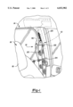
- FIG. 1 is a partial view of an exemplary vehicle interior shown incorporating an energy absorbing seat belt mounting arrangement constructed in accordance with the teachings of a preferred embodiment of the present invention.
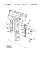
- FIG. 2 is an enlarged and partially exploded perspective view of the energy absorbing seat belt mounting arrangement of the present invention shown operatively associated with a portion of the vehicle B-pillar.
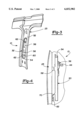
- FIG. 3 is a rear perspective view of the energy absorbing seat belt mounting arrangement of the present invention shown attached to the B-pillar.
- FIG. 4 is a side view of the energy absorbing seat belt mounting arrangement of FIGS. 2 and 3, further illustrating attachment to the B-pillar.
- an energy absorbing seat belt mounting arrangement constructed in accordance with the teachings of a preferred embodiment of the present invention is generally identified with reference numeral 10.
- the mounting arrangement 10 is illustrated incorporated into an exemplary occupant restraint system 12 of a motor vehicle 14.
- a brief understanding of the occupant restraint system 12 is warranted.
- FIG. 1 The present invention is illustrated in FIG. 1 as applied to a three-point vehicle safety belt system 12 for restraining forward movement of a vehicle occupant in the event of deceleration of the vehicle 14 above a predetermined magnitude, such as occurs in a vehicle collision. It should be understood that the present invention could be applied to other safety belt systems.
- a vehicle seat is illustrated as a front driver seat 16 in the vehicle 14.
- the vehicle seat 16 is of conventional construction including a seat back 18.
- the vehicle safety belt system 12 includes a length of seat belt webbing 20 which is extendable about the vehicle occupant (not shown) in a conventional manner. While not specifically shown, it will be understood that the seat belt webbing 20 conventionally includes one end anchored to the floor of the vehicle body, passes through a D-ring 22 positioned along the B-pillar 23 and extends vertically downward to seat belt retractor (not shown) of known construction.
- a tongue assembly 24 is carried by the seat belt webbing 20 and is adapted to be received in a buckle secured to the vehicle body. When the tongue assembly 24 and buckle are joined, a shoulder belt section of the seat belt webbing 20 extends from the tongue assembly 24 diagonally across the seat back 18.
- the mounting arrangement 10 is shown to include an anchorage assembly 30 and a mounting plate 32.
- the anchorage assembly 30 includes a vertical elongated track 34 having a generally C-shaped cross section.
- the track 34 is adapted to receive a vertically adjustable unit 36 which has a tapped hole 38 for mounting of the D-ring 22 with a threaded fastener 40.
- the vertically adjustable unit 36 further includes a locating pin (not shown) which cooperates with a plurality of holes 42 located in the track 34 for positively locating the adjustable unit 36.
- a lever 44 outwardly extends from the vertically adjustable unit 36 which is operable for overcoming a spring force which normally biases the locating pin into engagement with one of the holes 42.
- the tapping plate 32 includes a first end 46, a second end 48, and an intermediate portion 50, and is shown preferably attached to an inner side 52 of the B-pillar 23. Structural integrity of the mounting plate 32 is enhanced by a peripheral flange 54 which surrounds the mounting plate 32. The intermediate portion 56 of the mounting plate 32 is fixedly secured to the B-pillars 23 through welds 50.
- the anchorage assembly 30 is attached to the mounting plate 32 at first and second points 58 and 60 of the mounting plate 32 which are vertically spaced apart.
- the first and second points 58 and 60 of the mounting plate 32 are each preferably boss portions 58 and 60 integrally formed with the mounting plate 32 and internally threaded to each receive a threaded fastener 62.
- the first boss portion 58 extends in an inboard direction through an aperture 64 provided in the B-pillar 23.
- the threaded fastener 62 which cooperates with the first boss portion 58 passes through an aperture 66 formed in the track 34 and through the first boss portion 58.
- the head 68 of the threaded fastener 62 is adapted to receive the locating pin of the vertically adjustable member 36.
- the second boss portion 60 is illustrated to extend in an outboard direction and is also internally threaded.
- the second boss portion 60 receives a fastener 62 which passes through an aperture (not specifically shown) provided in a stepped portion 70 integrally formed with the track 34 of the anchorage assembly 30.
- boss portions 58 and 60 of the mounting plate 32 are preferably formed through extrusion. It will be appreciated that the boss portions 58 and 60 may alternatively be formed to extend in the same direction, either inboard or outboard. In the exemplary embodiment illustrated, the boss portions 58 and 60 space the anchorage assembly 30 approximately 12 mm from the B-pillar 23.
- the mounting plate 32 is unitarily constructed of cold rolled steel having a thickness of approximately 2.5 mm. However, alternative materials having suitable strength requirements may be utilized.
- the intermediate portion 50 of the mounting plate 32 is spot welded to the B-pillar 23 along a first horizontal line approximately 1.25 inches from a centerline of the first boss portion 58 and 1.25 inches from a centerline of the second boss portion 60.
- the spot welds 56 are preferably spaced approximately 3/8 inch from the edge of the tapping plate 32.
- the mounting arrangement 10 is able to withstand a tension load applied through the D-ring 22 of approximately 5,000 to 6,000 pounds. Further in this application, the first and second points 58 and 60 on the mounting plate are adapted to yield under a compression load applied to the anchorage assembly 30 of approximately 1,400 pounds.
Abstract
Description
Claims (14)
Priority Applications (1)
| Application Number | Priority Date | Filing Date | Title |
|---|---|---|---|
| US08/963,750 US6032982A (en) | 1997-11-04 | 1997-11-04 | Energy absorbing B-pillar seat belt mounting arrangement |
Applications Claiming Priority (1)
| Application Number | Priority Date | Filing Date | Title |
|---|---|---|---|
| US08/963,750 US6032982A (en) | 1997-11-04 | 1997-11-04 | Energy absorbing B-pillar seat belt mounting arrangement |
Publications (1)
| Publication Number | Publication Date |
|---|---|
| US6032982A true US6032982A (en) | 2000-03-07 |
Family
ID=25507652
Family Applications (1)
| Application Number | Title | Priority Date | Filing Date |
|---|---|---|---|
| US08/963,750 Expired - Lifetime US6032982A (en) | 1997-11-04 | 1997-11-04 | Energy absorbing B-pillar seat belt mounting arrangement |
Country Status (1)
| Country | Link |
|---|---|
| US (1) | US6032982A (en) |
Cited By (13)
| Publication number | Priority date | Publication date | Assignee | Title |
|---|---|---|---|---|
| US6354628B1 (en) * | 2000-01-13 | 2002-03-12 | Ford-Global Technologies, Inc. | Seat belt anchor assembly |
| US6364359B1 (en) * | 2000-03-11 | 2002-04-02 | Dr. Ing. H.C.F. Porsche Ag | Arrangement for a belt level adjuster of a safety belt system |
| EP1132264A3 (en) * | 2000-03-11 | 2002-05-15 | Dr.Ing. h.c.F. Porsche Aktiengesellschaft | Height adjustment device for a vehicle safety belt system |
| EP1132265A3 (en) * | 2000-03-11 | 2002-05-15 | Dr.Ing. h.c.F. Porsche Aktiengesellschaft | Belt height adjustment device for a safety belt system |
| US6416113B1 (en) | 2000-09-07 | 2002-07-09 | Guardian Industries Corp. | Applique for vehicle B-pillar |
| US6485049B1 (en) * | 2000-12-21 | 2002-11-26 | Daimlerchrysler Corporation | Trim panel assembly for a motor vehicle |
| US20030173768A1 (en) * | 2002-03-18 | 2003-09-18 | Takata-Petri Ag | Safety belt apparatus |
| US7252343B1 (en) * | 2005-07-27 | 2007-08-07 | Honda Motor Co., Ltd. | Portable child seat demonstration device |
| US20080100122A1 (en) * | 2006-10-30 | 2008-05-01 | Key Safety Systems, Inc. | Seat belt arrangement for child occupants of a vehicle |
| US20080288141A1 (en) * | 2007-05-16 | 2008-11-20 | Clute Gunter K | Active Anti-Bunching D-Ring Seat Belt System |
| US20090152896A1 (en) * | 2006-05-11 | 2009-06-18 | Gm Global Technology Operations, Inc. | Reinforcement module for a motor vehicle body |
| CN104401291A (en) * | 2014-10-16 | 2015-03-11 | 浙江吉利汽车研究院有限公司 | Layout method of safety belt winding device and car with safety belt winding device |
| US11014528B2 (en) * | 2019-04-19 | 2021-05-25 | Toyota Motor Engineering & Manufacturing North America, Inc. | Energy absorption for D-ring attachment bracket |
Citations (6)
| Publication number | Priority date | Publication date | Assignee | Title |
|---|---|---|---|---|
| US5265908A (en) * | 1992-03-16 | 1993-11-30 | Trw Vehicle Safety Systems Inc. | Height adjuster for D-ring |
| US5330144A (en) * | 1993-01-08 | 1994-07-19 | Square D Company | Frame structure and assembly for wall mounting a speaker or camera |
| US5344188A (en) * | 1993-12-29 | 1994-09-06 | Chrysler Corporation | Vehicle seat belt anchor arrangement |
| US5529344A (en) * | 1993-11-30 | 1996-06-25 | Toyota Jidosha Kabushiki Kaisha | Seat belt device for automobile |
| US5791687A (en) * | 1995-12-27 | 1998-08-11 | Honda Giken Kogyo Kabushiki Kaisha | Seat belt device for vehicle |
| US5842719A (en) * | 1995-11-20 | 1998-12-01 | Kabushiki Kaisha Tokai-Rika-Denki-Seisakusho | Energy absorbing shoulder anchor structure |
-
1997
- 1997-11-04 US US08/963,750 patent/US6032982A/en not_active Expired - Lifetime
Patent Citations (6)
| Publication number | Priority date | Publication date | Assignee | Title |
|---|---|---|---|---|
| US5265908A (en) * | 1992-03-16 | 1993-11-30 | Trw Vehicle Safety Systems Inc. | Height adjuster for D-ring |
| US5330144A (en) * | 1993-01-08 | 1994-07-19 | Square D Company | Frame structure and assembly for wall mounting a speaker or camera |
| US5529344A (en) * | 1993-11-30 | 1996-06-25 | Toyota Jidosha Kabushiki Kaisha | Seat belt device for automobile |
| US5344188A (en) * | 1993-12-29 | 1994-09-06 | Chrysler Corporation | Vehicle seat belt anchor arrangement |
| US5842719A (en) * | 1995-11-20 | 1998-12-01 | Kabushiki Kaisha Tokai-Rika-Denki-Seisakusho | Energy absorbing shoulder anchor structure |
| US5791687A (en) * | 1995-12-27 | 1998-08-11 | Honda Giken Kogyo Kabushiki Kaisha | Seat belt device for vehicle |
Cited By (18)
| Publication number | Priority date | Publication date | Assignee | Title |
|---|---|---|---|---|
| US6354628B1 (en) * | 2000-01-13 | 2002-03-12 | Ford-Global Technologies, Inc. | Seat belt anchor assembly |
| US6364359B1 (en) * | 2000-03-11 | 2002-04-02 | Dr. Ing. H.C.F. Porsche Ag | Arrangement for a belt level adjuster of a safety belt system |
| EP1132264A3 (en) * | 2000-03-11 | 2002-05-15 | Dr.Ing. h.c.F. Porsche Aktiengesellschaft | Height adjustment device for a vehicle safety belt system |
| EP1132265A3 (en) * | 2000-03-11 | 2002-05-15 | Dr.Ing. h.c.F. Porsche Aktiengesellschaft | Belt height adjustment device for a safety belt system |
| US6431603B2 (en) * | 2000-03-11 | 2002-08-13 | Dr. Ing. H.C.F. Porsche Ag | Safety belt height adjusting device |
| US6460890B2 (en) | 2000-03-11 | 2002-10-08 | Dr. Ing. H.C.F. Porsche Ag | Arrangement for a belt level adjuster of a safety belt system |
| US6416113B1 (en) | 2000-09-07 | 2002-07-09 | Guardian Industries Corp. | Applique for vehicle B-pillar |
| US6485049B1 (en) * | 2000-12-21 | 2002-11-26 | Daimlerchrysler Corporation | Trim panel assembly for a motor vehicle |
| US20030173768A1 (en) * | 2002-03-18 | 2003-09-18 | Takata-Petri Ag | Safety belt apparatus |
| US6871877B2 (en) * | 2002-03-18 | 2005-03-29 | Takata-Petri (Ulm) Gmbh | Safety belt apparatus |
| US7252343B1 (en) * | 2005-07-27 | 2007-08-07 | Honda Motor Co., Ltd. | Portable child seat demonstration device |
| US20090152896A1 (en) * | 2006-05-11 | 2009-06-18 | Gm Global Technology Operations, Inc. | Reinforcement module for a motor vehicle body |
| US20080100122A1 (en) * | 2006-10-30 | 2008-05-01 | Key Safety Systems, Inc. | Seat belt arrangement for child occupants of a vehicle |
| US7520532B2 (en) * | 2006-10-30 | 2009-04-21 | Key Safety Systems, Inc. | Seat belt arrangement for child occupants of a vehicle |
| US20080288141A1 (en) * | 2007-05-16 | 2008-11-20 | Clute Gunter K | Active Anti-Bunching D-Ring Seat Belt System |
| US7806439B2 (en) | 2007-05-16 | 2010-10-05 | Autoliv Asp, Inc. | Active anti-bunching D-ring seat belt system |
| CN104401291A (en) * | 2014-10-16 | 2015-03-11 | 浙江吉利汽车研究院有限公司 | Layout method of safety belt winding device and car with safety belt winding device |
| US11014528B2 (en) * | 2019-04-19 | 2021-05-25 | Toyota Motor Engineering & Manufacturing North America, Inc. | Energy absorption for D-ring attachment bracket |
Similar Documents
| Publication | Publication Date | Title |
|---|---|---|
| US6032982A (en) | Energy absorbing B-pillar seat belt mounting arrangement | |
| US6302437B1 (en) | Vehicle glove box assembly having knee restraint capabilities | |
| US6170874B1 (en) | Variable energy-absorbing steering column | |
| US5863071A (en) | Seat belt anchor device for an automobile | |
| US5615917A (en) | Apparatus for use in a vehicle occupant restraint system | |
| US7059675B2 (en) | Motion controlling plate for seat and seat system for a mobile vehicle | |
| US6199907B1 (en) | Method and apparatus for absorbing impact energy | |
| JPH06239199A (en) | Anchor device for seat belt | |
| US11180110B2 (en) | Vehicle buckle assembly | |
| US4232895A (en) | Impact absorbing device for protecting vehicle's occupant from impact caused by collision | |
| US6447011B1 (en) | Safety belt arrangement for motor vehicles | |
| US5842719A (en) | Energy absorbing shoulder anchor structure | |
| US20030127842A1 (en) | Vehicle roof liner for occupant protection | |
| US20070200400A1 (en) | Support Structure For Roof Reinforcement | |
| US20050189802A1 (en) | School bus occupant restraint passenger seat | |
| US10703328B2 (en) | Seatbelt guide assembly | |
| CN111183058A (en) | Vehicle with passenger protection system having increased free space available in the vehicle interior | |
| US7607508B2 (en) | Vehicle side collision occupant restraint system | |
| US7744125B2 (en) | Occupant safety device for roof reinforcement | |
| US3534979A (en) | Safety vehicle | |
| US10405613B2 (en) | Extendable two-piece seatbelt tongue | |
| CN101395045A (en) | Seat safety pretension device | |
| US5478116A (en) | D-ring mounting assembly | |
| JP4395875B2 (en) | Seat belt anchor structure | |
| EP1031475A2 (en) | Protection system for rear impact crashes |
Legal Events
| Date | Code | Title | Description |
|---|---|---|---|
| AS | Assignment |
Owner name: CHRYSLER CORPORATION, MICHIGAN Free format text: ASSIGNMENT OF ASSIGNORS INTEREST;ASSIGNORS:PAKULSKY, BRIAN R.;STOUPPE, JIM S.;SUCHENEK, DAVID;AND OTHERS;REEL/FRAME:008804/0641;SIGNING DATES FROM 19971020 TO 19971103 |
|
| STCF | Information on status: patent grant |
Free format text: PATENTED CASE |
|
| FPAY | Fee payment |
Year of fee payment: 4 |
|
| AS | Assignment |
Owner name: WILMINGTON TRUST COMPANY, DELAWARE Free format text: GRANT OF SECURITY INTEREST IN PATENT RIGHTS - FIRST PRIORITY;ASSIGNOR:CHRYSLER LLC;REEL/FRAME:019773/0001 Effective date: 20070803 Owner name: WILMINGTON TRUST COMPANY,DELAWARE Free format text: GRANT OF SECURITY INTEREST IN PATENT RIGHTS - FIRST PRIORITY;ASSIGNOR:CHRYSLER LLC;REEL/FRAME:019773/0001 Effective date: 20070803 |
|
| AS | Assignment |
Owner name: WILMINGTON TRUST COMPANY, DELAWARE Free format text: GRANT OF SECURITY INTEREST IN PATENT RIGHTS - SECOND PRIORITY;ASSIGNOR:CHRYSLER LLC;REEL/FRAME:019767/0810 Effective date: 20070803 Owner name: WILMINGTON TRUST COMPANY,DELAWARE Free format text: GRANT OF SECURITY INTEREST IN PATENT RIGHTS - SECOND PRIORITY;ASSIGNOR:CHRYSLER LLC;REEL/FRAME:019767/0810 Effective date: 20070803 |
|
| FPAY | Fee payment |
Year of fee payment: 8 |
|
| AS | Assignment |
Owner name: DAIMLERCHRYSLER CORPORATION, MICHIGAN Free format text: CHANGE OF NAME;ASSIGNOR:CHRYSLER CORPORATION;REEL/FRAME:021826/0034 Effective date: 19981116 |
|
| AS | Assignment |
Owner name: CHRYSLER LLC, MICHIGAN Free format text: CHANGE OF NAME;ASSIGNOR:DAIMLERCHRYSLER COMPANY LLC;REEL/FRAME:021832/0233 Effective date: 20070727 Owner name: DAIMLERCHRYSLER COMPANY LLC, MICHIGAN Free format text: CHANGE OF NAME;ASSIGNOR:DAIMLERCHRYSLER CORPORATION;REEL/FRAME:021832/0256 Effective date: 20070329 |
|
| AS | Assignment |
Owner name: US DEPARTMENT OF THE TREASURY, DISTRICT OF COLUMBI Free format text: GRANT OF SECURITY INTEREST IN PATENT RIGHTS - THIR;ASSIGNOR:CHRYSLER LLC;REEL/FRAME:022259/0188 Effective date: 20090102 Owner name: US DEPARTMENT OF THE TREASURY,DISTRICT OF COLUMBIA Free format text: GRANT OF SECURITY INTEREST IN PATENT RIGHTS - THIR;ASSIGNOR:CHRYSLER LLC;REEL/FRAME:022259/0188 Effective date: 20090102 |
|
| AS | Assignment |
Owner name: CHRYSLER LLC, MICHIGAN Free format text: RELEASE BY SECURED PARTY;ASSIGNOR:US DEPARTMENT OF THE TREASURY;REEL/FRAME:022910/0273 Effective date: 20090608 |
|
| AS | Assignment |
Owner name: CHRYSLER LLC, MICHIGAN Free format text: RELEASE OF SECURITY INTEREST IN PATENT RIGHTS - FIRST PRIORITY;ASSIGNOR:WILMINGTON TRUST COMPANY;REEL/FRAME:022910/0498 Effective date: 20090604 Owner name: CHRYSLER LLC, MICHIGAN Free format text: RELEASE OF SECURITY INTEREST IN PATENT RIGHTS - SECOND PRIORITY;ASSIGNOR:WILMINGTON TRUST COMPANY;REEL/FRAME:022910/0740 Effective date: 20090604 Owner name: NEW CARCO ACQUISITION LLC, MICHIGAN Free format text: ASSIGNMENT OF ASSIGNORS INTEREST;ASSIGNOR:CHRYSLER LLC;REEL/FRAME:022915/0001 Effective date: 20090610 Owner name: THE UNITED STATES DEPARTMENT OF THE TREASURY, DIST Free format text: SECURITY AGREEMENT;ASSIGNOR:NEW CARCO ACQUISITION LLC;REEL/FRAME:022915/0489 Effective date: 20090610 Owner name: CHRYSLER LLC,MICHIGAN Free format text: RELEASE OF SECURITY INTEREST IN PATENT RIGHTS - FIRST PRIORITY;ASSIGNOR:WILMINGTON TRUST COMPANY;REEL/FRAME:022910/0498 Effective date: 20090604 Owner name: CHRYSLER LLC,MICHIGAN Free format text: RELEASE OF SECURITY INTEREST IN PATENT RIGHTS - SECOND PRIORITY;ASSIGNOR:WILMINGTON TRUST COMPANY;REEL/FRAME:022910/0740 Effective date: 20090604 Owner name: NEW CARCO ACQUISITION LLC,MICHIGAN Free format text: ASSIGNMENT OF ASSIGNORS INTEREST;ASSIGNOR:CHRYSLER LLC;REEL/FRAME:022915/0001 Effective date: 20090610 Owner name: THE UNITED STATES DEPARTMENT OF THE TREASURY,DISTR Free format text: SECURITY AGREEMENT;ASSIGNOR:NEW CARCO ACQUISITION LLC;REEL/FRAME:022915/0489 Effective date: 20090610 |
|
| AS | Assignment |
Owner name: CHRYSLER GROUP LLC, MICHIGAN Free format text: CHANGE OF NAME;ASSIGNOR:NEW CARCO ACQUISITION LLC;REEL/FRAME:022919/0126 Effective date: 20090610 Owner name: CHRYSLER GROUP LLC,MICHIGAN Free format text: CHANGE OF NAME;ASSIGNOR:NEW CARCO ACQUISITION LLC;REEL/FRAME:022919/0126 Effective date: 20090610 |
|
| AS | Assignment |
Owner name: CHRYSLER GROUP LLC, MICHIGAN Free format text: RELEASE BY SECURED PARTY;ASSIGNOR:THE UNITED STATES DEPARTMENT OF THE TREASURY;REEL/FRAME:026343/0298 Effective date: 20110524 Owner name: CHRYSLER GROUP GLOBAL ELECTRIC MOTORCARS LLC, NORT Free format text: RELEASE BY SECURED PARTY;ASSIGNOR:THE UNITED STATES DEPARTMENT OF THE TREASURY;REEL/FRAME:026343/0298 Effective date: 20110524 |
|
| AS | Assignment |
Owner name: CITIBANK, N.A., NEW YORK Free format text: SECURITY AGREEMENT;ASSIGNOR:CHRYSLER GROUP LLC;REEL/FRAME:026404/0123 Effective date: 20110524 |
|
| AS | Assignment |
Owner name: CITIBANK, N.A., NEW YORK Free format text: SECURITY AGREEMENT;ASSIGNOR:CHRYSLER GROUP LLC;REEL/FRAME:026435/0652 Effective date: 20110524 |
|
| FPAY | Fee payment |
Year of fee payment: 12 |
|
| AS | Assignment |
Owner name: JPMORGAN CHASE BANK, N.A., ILLINOIS Free format text: SECURITY AGREEMENT;ASSIGNOR:CHRYSLER GROUP LLC;REEL/FRAME:032384/0640 Effective date: 20140207 |
|
| AS | Assignment |
Owner name: FCA US LLC, MICHIGAN Free format text: CHANGE OF NAME;ASSIGNOR:CHRYSLER GROUP LLC;REEL/FRAME:035553/0356 Effective date: 20141203 |
|
| AS | Assignment |
Owner name: FCA US LLC, FORMERLY KNOWN AS CHRYSLER GROUP LLC, Free format text: RELEASE OF SECURITY INTEREST RELEASING SECOND-LIEN SECURITY INTEREST PREVIOUSLY RECORDED AT REEL 026426 AND FRAME 0644, REEL 026435 AND FRAME 0652, AND REEL 032384 AND FRAME 0591;ASSIGNOR:CITIBANK, N.A.;REEL/FRAME:037784/0001 Effective date: 20151221 |
|
| AS | Assignment |
Owner name: FCA US LLC (FORMERLY KNOWN AS CHRYSLER GROUP LLC), Free format text: RELEASE BY SECURED PARTY;ASSIGNOR:CITIBANK, N.A.;REEL/FRAME:042885/0255 Effective date: 20170224 |
|
| AS | Assignment |
Owner name: FCA US LLC (FORMERLY KNOWN AS CHRYSLER GROUP LLC), Free format text: RELEASE BY SECURED PARTY;ASSIGNOR:JPMORGAN CHASE BANK, N.A.;REEL/FRAME:048177/0356 Effective date: 20181113 |