EP1115587B1 - Armature de sommet pour pneumatique radial - Google Patents
Armature de sommet pour pneumatique radial Download PDFInfo
- Publication number
- EP1115587B1 EP1115587B1 EP99953746A EP99953746A EP1115587B1 EP 1115587 B1 EP1115587 B1 EP 1115587B1 EP 99953746 A EP99953746 A EP 99953746A EP 99953746 A EP99953746 A EP 99953746A EP 1115587 B1 EP1115587 B1 EP 1115587B1
- Authority
- EP
- European Patent Office
- Prior art keywords
- reinforcement
- layer
- decoupling
- tyre according
- ply
- Prior art date
- Legal status (The legal status is an assumption and is not a legal conclusion. Google has not performed a legal analysis and makes no representation as to the accuracy of the status listed.)
- Expired - Lifetime
Links
- 230000002787 reinforcement Effects 0.000 title claims description 74
- 229920001971 elastomer Polymers 0.000 claims description 55
- 239000005060 rubber Substances 0.000 claims description 55
- 239000011324 bead Substances 0.000 claims description 7
- 238000013016 damping Methods 0.000 claims description 6
- 238000004804 winding Methods 0.000 claims description 3
- 239000010410 layer Substances 0.000 description 57
- 230000003014 reinforcing effect Effects 0.000 description 10
- 239000000203 mixture Substances 0.000 description 8
- 230000008901 benefit Effects 0.000 description 5
- 239000011248 coating agent Substances 0.000 description 5
- 238000000576 coating method Methods 0.000 description 5
- 238000005096 rolling process Methods 0.000 description 5
- 238000012360 testing method Methods 0.000 description 5
- 239000004677 Nylon Substances 0.000 description 3
- 230000006872 improvement Effects 0.000 description 3
- 229920001778 nylon Polymers 0.000 description 3
- 239000002356 single layer Substances 0.000 description 3
- 240000008042 Zea mays Species 0.000 description 2
- 230000000295 complement effect Effects 0.000 description 2
- 238000009434 installation Methods 0.000 description 2
- 238000004519 manufacturing process Methods 0.000 description 2
- 239000000463 material Substances 0.000 description 2
- 239000002184 metal Substances 0.000 description 2
- 230000004308 accommodation Effects 0.000 description 1
- 239000004760 aramid Substances 0.000 description 1
- 229920003235 aromatic polyamide Polymers 0.000 description 1
- 230000000712 assembly Effects 0.000 description 1
- 238000000429 assembly Methods 0.000 description 1
- 238000003490 calendering Methods 0.000 description 1
- 238000012512 characterization method Methods 0.000 description 1
- 150000001875 compounds Chemical class 0.000 description 1
- 235000009508 confectionery Nutrition 0.000 description 1
- 239000000470 constituent Substances 0.000 description 1
- 238000013461 design Methods 0.000 description 1
- 230000002349 favourable effect Effects 0.000 description 1
- 239000011152 fibreglass Substances 0.000 description 1
- 239000000446 fuel Substances 0.000 description 1
- 238000005259 measurement Methods 0.000 description 1
- 229920000728 polyester Polymers 0.000 description 1
- 238000002360 preparation method Methods 0.000 description 1
- 230000009467 reduction Effects 0.000 description 1
- 238000011160 research Methods 0.000 description 1
- 230000004044 response Effects 0.000 description 1
- 238000000926 separation method Methods 0.000 description 1
- 238000010008 shearing Methods 0.000 description 1
- 238000004513 sizing Methods 0.000 description 1
- 238000004381 surface treatment Methods 0.000 description 1
- 239000004753 textile Substances 0.000 description 1
- 230000007704 transition Effects 0.000 description 1
- 238000004073 vulcanization Methods 0.000 description 1
Images


Classifications
-
- B—PERFORMING OPERATIONS; TRANSPORTING
- B60—VEHICLES IN GENERAL
- B60C—VEHICLE TYRES; TYRE INFLATION; TYRE CHANGING; CONNECTING VALVES TO INFLATABLE ELASTIC BODIES IN GENERAL; DEVICES OR ARRANGEMENTS RELATED TO TYRES
- B60C9/00—Reinforcements or ply arrangement of pneumatic tyres
- B60C9/18—Structure or arrangement of belts or breakers, crown-reinforcing or cushioning layers
- B60C9/20—Structure or arrangement of belts or breakers, crown-reinforcing or cushioning layers built-up from rubberised plies each having all cords arranged substantially parallel
- B60C9/22—Structure or arrangement of belts or breakers, crown-reinforcing or cushioning layers built-up from rubberised plies each having all cords arranged substantially parallel the plies being arranged with all cords disposed along the circumference of the tyre
-
- B—PERFORMING OPERATIONS; TRANSPORTING
- B60—VEHICLES IN GENERAL
- B60C—VEHICLE TYRES; TYRE INFLATION; TYRE CHANGING; CONNECTING VALVES TO INFLATABLE ELASTIC BODIES IN GENERAL; DEVICES OR ARRANGEMENTS RELATED TO TYRES
- B60C9/00—Reinforcements or ply arrangement of pneumatic tyres
- B60C9/18—Structure or arrangement of belts or breakers, crown-reinforcing or cushioning layers
- B60C9/20—Structure or arrangement of belts or breakers, crown-reinforcing or cushioning layers built-up from rubberised plies each having all cords arranged substantially parallel
-
- B—PERFORMING OPERATIONS; TRANSPORTING
- B60—VEHICLES IN GENERAL
- B60C—VEHICLE TYRES; TYRE INFLATION; TYRE CHANGING; CONNECTING VALVES TO INFLATABLE ELASTIC BODIES IN GENERAL; DEVICES OR ARRANGEMENTS RELATED TO TYRES
- B60C9/00—Reinforcements or ply arrangement of pneumatic tyres
- B60C9/18—Structure or arrangement of belts or breakers, crown-reinforcing or cushioning layers
- B60C9/1835—Rubber strips or cushions at the belt edges
- B60C2009/1842—Width or thickness of the strips or cushions
-
- Y—GENERAL TAGGING OF NEW TECHNOLOGICAL DEVELOPMENTS; GENERAL TAGGING OF CROSS-SECTIONAL TECHNOLOGIES SPANNING OVER SEVERAL SECTIONS OF THE IPC; TECHNICAL SUBJECTS COVERED BY FORMER USPC CROSS-REFERENCE ART COLLECTIONS [XRACs] AND DIGESTS
- Y10—TECHNICAL SUBJECTS COVERED BY FORMER USPC
- Y10T—TECHNICAL SUBJECTS COVERED BY FORMER US CLASSIFICATION
- Y10T152/00—Resilient tires and wheels
- Y10T152/10—Tires, resilient
- Y10T152/10495—Pneumatic tire or inner tube
- Y10T152/10504—Asymmetric tyre
-
- Y—GENERAL TAGGING OF NEW TECHNOLOGICAL DEVELOPMENTS; GENERAL TAGGING OF CROSS-SECTIONAL TECHNOLOGIES SPANNING OVER SEVERAL SECTIONS OF THE IPC; TECHNICAL SUBJECTS COVERED BY FORMER USPC CROSS-REFERENCE ART COLLECTIONS [XRACs] AND DIGESTS
- Y10—TECHNICAL SUBJECTS COVERED BY FORMER USPC
- Y10T—TECHNICAL SUBJECTS COVERED BY FORMER US CLASSIFICATION
- Y10T152/00—Resilient tires and wheels
- Y10T152/10—Tires, resilient
- Y10T152/10495—Pneumatic tire or inner tube
- Y10T152/10765—Characterized by belt or breaker structure
- Y10T152/10792—Structure where each bias angle reinforcing cord ply has no opposingly angled ply
-
- Y—GENERAL TAGGING OF NEW TECHNOLOGICAL DEVELOPMENTS; GENERAL TAGGING OF CROSS-SECTIONAL TECHNOLOGIES SPANNING OVER SEVERAL SECTIONS OF THE IPC; TECHNICAL SUBJECTS COVERED BY FORMER USPC CROSS-REFERENCE ART COLLECTIONS [XRACs] AND DIGESTS
- Y10—TECHNICAL SUBJECTS COVERED BY FORMER USPC
- Y10T—TECHNICAL SUBJECTS COVERED BY FORMER US CLASSIFICATION
- Y10T152/00—Resilient tires and wheels
- Y10T152/10—Tires, resilient
- Y10T152/10495—Pneumatic tire or inner tube
- Y10T152/10765—Characterized by belt or breaker structure
- Y10T152/1081—Breaker or belt characterized by the chemical composition or physical properties of elastomer or the like
Definitions
- the invention relates to the tops of tires and in particular rubber decoupling of the reinforcement plies from these peaks.
- the crowns of the tires usually include a carcass reinforcement, a belt reinforcement with usually at least two reinforcing plies superimposed formed of parallel threads in each tablecloth and crossed from one tablecloth to another and a tread.
- Document FR 2 499 912 describes such a tire in which, between two plies of reinforcement are arranged axially adjacent two layers of rubber different mechanical properties.
- tops of the tires are in contact with the ground and must in particular transmit the forces to the wheels through the sidewalls and beads necessary to guide the vehicles. So that the road behavior of vehicles is satisfactory, the tops must have a relatively high rigidity for example on the flanks. It is an ongoing goal to try to achieve such rigidity raised in a simple way and the most economical possible.
- the decoupling gums of the threads of the belt reinforcement participate in obtaining high rigidity. This is why, these decoupling gums usually have a high modulus of elasticity.
- the decoupling gums in contact with the wires of the carcass reinforcements usually have a low modulus of elasticity because they must withstand without damage the high deformations they undergo in the sidewalls of the tires.
- the subject of the invention is a tire whose crown structure is improved to facilitate its manufacturing process and thus make it more economical, as well as for improve its quality and performance.
- the invention also relates, according to a first variant, to an embodiment of the intended primarily to lower rolling resistance and, for a second variant, an embodiment intended mainly to improve the rigidity of the crown.
- the term “yarn” means both monofilaments and multifilaments, or assemblies such as cables, twists or even any what type of equivalent assembly, and this, whatever the material and the treatment of these threads, for example surface treatment or coating, in particular of rubber having underwent vulcanization, or pre-sizing to promote adhesion to the rubber.
- “Decoupling rubber layer” is understood to mean between two reinforcing plies adjacent rubber compound in contact with reinforcing threads of at least one of the two plies, adhering to these and filling the interstices between adjacent wires.
- the reinforcing plies are produced by application of calendered plies, consequently, between two reinforcement plies data, two layers of decoupling rubber are used, each one in contact with the threads of one of the two layers and having the same composition for the different tire areas.
- contact between a wire and a layer of decoupling rubber means that, at least part of the outer circumference of the wire is in intimate contact with the rubber mixture constituting decoupling gum. If the thread has a coating or coating, the term contact means that it is the circumference exterior of this coating or coating which is in intimate contact with the mixture rubber constituting the bonding rubber.
- modulus of elasticity of a rubber mixture is meant a modulus of secant extension obtained at a uniaxial extension deformation of the order of 10% after three cycles of accommodation and at room temperature.
- the tire according to the invention comprises a crown, two sidewalls and two beads, a carcass reinforcement anchored in the two beads and a belt reinforcement, this belt reinforcement comprising at least two reinforcing plies superimposed formed of parallel threads in each tablecloth and crossed from one tablecloth to another making angles ( ⁇ , ⁇ ) with the circumferential direction between 10 ° and 70 °.
- This pneumatic is characterized in that between the two reinforcing plies overlapped, are located, axially adjacent, at least two layers of decoupling gums with different mechanical properties, and in that each of said two layers of decoupling rubber is in contact with the wires said two superimposed reinforcement plies.
- This tire has the advantage of not having in any circumferential section (apart from the transition zones between the two adjacent layers of decoupling rubber) layer of single decoupling rubber between the two reinforcing plies of Mountain peak.
- This layer can have different properties in sections different circumferentials, for example in the center and on the edges of the sheets. it allows the nature and properties of this single layer to be adapted according to the objective of the tire designer.
- the layers of decoupling rubber are produced by a winding helical of a rubber mix profile directly on the wires of the radially inner reinforcement. This direct application of layers of gum decoupling on the wires of the reinforcement plies simplifies the manufacture of the tire.
- a first decoupling layer is placed between the central part of the two layers overlapping reinforcement, and a second decoupling layer is provided with a side at least of the first layer and extends, at least, to the lateral ends two overlapping reinforcement plies.
- the ratio between the elasticity modules of the second layer and the first layer is between 0.05 and 0.8 and preferably between 0.4 and 0.6.
- the elastic modulus of the decoupling rubber between the two reinforcement plies made up of crossed wires is significantly lower in the minus a lateral zone from the top of the tire to that of the decoupling rubber in the central area of the summit.
- the second layer of decoupling rubber has a factor value amortization tg ⁇ less than 0.08.
- Such a layer is very weakly hysteretic and contributes significantly to the gain in resistance to the advancement of the tire concerned.
- an additional reinforcement ply consisting of wires oriented in the direction circumferential and extending axially substantially like the second layer of decoupling rubber.
- This additional reinforcement ply can be placed radially externally or internally relative to the two plies of reinforcement superimposed or between these two layers.
- This first embodiment of a tire is more particularly suitable for tires with an H / B aspect ratio greater than 0.55.
- the ratio between the elasticity modules of the second layer and the first layer of decoupling gum is between 1.2 and 20 and preferably between 1.5 and 10.
- this second embodiment it is the first layer of decoupling rubber arranged in the central area of the two reinforcement plies which has a module lower elasticity than that of the layer of decoupling rubber placed in the lateral zones of the top of the tire.
- This second embodiment also has the advantage of making it possible to reduce the resistance to advancement without penalizing the drift thrust and duration properties life.
- This second embodiment is more particularly interesting with tires with an aspect ratio of less than 0.55.
- the two reinforcement plies between which are arranged axially two layers of decoupling rubber different mechanical properties are a crown reinforcement ply and a carcass reinforcement ply.
- This embodiment is more particularly advantageous when the belt reinforcement consists of a reinforcing ply the wires of which are oriented relative to the circumferential direction at an angle ⁇ between 10 ° and 70 ° and a reinforcement ply formed of parallel oriented wires substantially circumferentially.
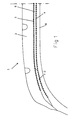
- FIG. 1 is shown, in partial meridian section and schematically, a first embodiment of a tire crown according to the invention.
- This summit 1 includes in particular a tread 2 and two reinforcing plies of vertex 3 and 4. These two layers are said to be crossed, they are superimposed and made up of parallel threads in each tablecloth and crossed from one tablecloth to the other by making with the circumferential direction of the angles ( ⁇ , ⁇ ) between 10 and 70 °.
- ⁇ , ⁇ the angle between 10 and 70 °.
- the two layers of decoupling rubber 6 and 10 are both in contact with the wires of both layers 3 and 4.
- the separation limit between the two layers 6 and 10 is preferably angled at a bevel.
- the vertex 1 comprises in particular a not shown radial carcass reinforcement.
- the wires of the plies 3 and 4 are arranged in such a way that they do not have any contact between them.
- the first layer of decoupling rubber 6 usually has a modulus of elasticity between 10 and 15 MPa.
- the wires of the two layers 3 and 4 are in contact with a second layer of decoupling rubber 10, of modulus of elasticity lower than that of the first layer.
- the ratio of the modules is between 0.05 and 0.8 and preferably, between 0.5 and 0.7. This lower modulus layer limits the amplitude of the stresses maximum shear at the ends of the sheets and therefore limits the dissipated energies by hysteresis during taxiing.
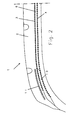
- FIG. 2 shows an alternative embodiment of the tire crown of FIG. 1 in which a partial ply 11 has been added.
- This ply 11 consists of wires oriented in the circumferential direction of the tire. These wires can be textile material, aramid, polyester, nylon or hybrid, fiberglass or metal.
- the ply 11 is arranged radially externally relative to the two plies 3 and 4 and extends axially only substantially above the two lateral ends of the plies 3 and 4.
- This ply has the advantage of limiting the amplitude of the stresses of shearing between the ends of the two plies 3 and 4 and thus preserving or even increase the drift thrust and lifespan properties (in the endurance sense) while having substantially improved the resistance to advancement of the tire.
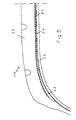
- This ply 11 can also be arranged radially internally relative to the two plies 3 and 4 ( Figure 4) as well as radially between the two plies 3 and 4 ( Figure 3).
- This embodiment with a layer of decoupling rubber of lower module and low hysteresis between the two crossed reinforcement plies and in at least one of the lateral ends of the crown is particularly suitable for tires of aspect ratio (height divided by width) H / B greater than 0.55.
- the layer with the highest modulus of elasticity is thus arranged at the lateral ends of the apex and that of lower modulus, and of lower hysteresis is arranged in the central part between the two reinforcement plies crossed 3 and 4.
- the layers of decoupling rubber placed towards the lateral ends of the crown have a contact length with the wires of the width cross-reinforcing ply weakest axial, the ply 3, which must be axially greater than 5 mm and, preferably greater than 20 mm to be effective. But, it is not necessary to increase this contact length beyond 1/3 of the axial width of the ply 3.
- This second embodiment is more particularly suitable for tires of aspect ratio less than 0.55.
- the tires underwent a rolling resistance test (at 60 km / h, pressure 2.1 bar and load 3500 N). This test measures the energy dissipated during taxiing and a favorable result is expressed by a figure less than 100. They have also undergone a characterization of their drift thrust, that is to say of the lateral force Y developed by the tire when driving at an imposed drift angle ⁇ . An increase in drift thrust is expressed by a figure greater than 100.
- the test was carried out with a load of 3500 N and an inflation pressure of 2 bars. Pneumatic RR Y ( ⁇ ) AT 100 100 B 95 95 VS 94 80 D 95 105
- Solution B showed a marked improvement in resistance to rolling with a limited decrease in drift thrust.
- Solution C has the same improvement in rolling resistance but with a much more marked reduction in the drift thrust.
- solution D presents an improvement in the properties of the tire in the two tests undergone.
- FIG. 5 shows another embodiment of the invention.
- the top 20 of this tire includes a tread 22, a reinforcement ply of vertex 23 whose wires make angles ⁇ between the circumferential direction 10 and 70 degrees, and a carcass reinforcement ply 24. Between the two plies of superimposed reinforcement, there is a first 25 and a second 26 layers of decoupling gums, arranged adjacent to each other. These layers are directly in contact with the wires of the two reinforcing plies 23 and 24. The layer 25 is arranged in the center of the two layers, layer 26 in a lateral zone.
- Such a tire also includes in its crown reinforcement a complementary ply comprising wires, metallic or not, circumferentially oriented (not shown in Figure 5).
- the modulus of elasticity, and / or the damping factor tg ⁇ of the two layers 25 and 26 may vary as in the two embodiments previously described.
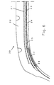
- FIG. 6 is presented a variant embodiment of the tire crown of the figure 5.
- the complementary reinforcement ply of crown 31 comprising wires, metallic or not, circumferentially oriented.
- the crown 30 further comprises a partial ply 32 disposed radially internally relative to the two carcass plies 24 and crown reinforcement 23. This ply 32 significantly improves the properties of drift thrust, resistance to advancement and tire life when the module decoupling rubber layer lower and lower hysteresis is arranged at the lateral ends of the vertex.
- the partial ply 31 further enhances the gain in tire drift thrust. This applies to tires intended to run at very high speed.
Landscapes
- Engineering & Computer Science (AREA)
- Mechanical Engineering (AREA)
- Tires In General (AREA)
Applications Claiming Priority (3)
| Application Number | Priority Date | Filing Date | Title |
|---|---|---|---|
| FR9812594 | 1998-10-02 | ||
| FR9812594 | 1998-10-02 | ||
| PCT/EP1999/007263 WO2000020233A1 (fr) | 1998-10-02 | 1999-10-01 | Armature de sommet pour pneumatique radial |
Publications (2)
| Publication Number | Publication Date |
|---|---|
| EP1115587A1 EP1115587A1 (fr) | 2001-07-18 |
| EP1115587B1 true EP1115587B1 (fr) | 2003-03-19 |
Family
ID=9531325
Family Applications (1)
| Application Number | Title | Priority Date | Filing Date |
|---|---|---|---|
| EP99953746A Expired - Lifetime EP1115587B1 (fr) | 1998-10-02 | 1999-10-01 | Armature de sommet pour pneumatique radial |
Country Status (8)
| Country | Link |
|---|---|
| US (2) | US6776205B2 (enExample) |
| EP (1) | EP1115587B1 (enExample) |
| JP (1) | JP4589532B2 (enExample) |
| KR (1) | KR100737185B1 (enExample) |
| BR (1) | BR9914219A (enExample) |
| DE (1) | DE69906103T2 (enExample) |
| ES (1) | ES2193755T3 (enExample) |
| WO (1) | WO2000020233A1 (enExample) |
Families Citing this family (26)
| Publication number | Priority date | Publication date | Assignee | Title |
|---|---|---|---|---|
| FR2784054A1 (fr) * | 1998-10-02 | 2000-04-07 | Michelin Soc Tech | Armature de sommet pour pneumatique radial |
| US7268794B2 (en) * | 2000-10-30 | 2007-09-11 | Yamaha Corporation | Method of printing label on optical disk, optical disk unit, and optical disk |
| US7094302B2 (en) | 2001-03-29 | 2006-08-22 | Pirelli Pneumatici S.P.A. | Method of forming a belt structure in a tire, in particular for motorcycle wheels |
| ES2231693T3 (es) * | 2001-03-29 | 2005-05-16 | Pirelli Pneumatici S.P.A. | Procedimiento de fabricacion de una estructura de cintura en particular para neumaticos de motocicleta. |
| JP4381982B2 (ja) * | 2002-08-09 | 2009-12-09 | ソシエテ ド テクノロジー ミシュラン | 二輪付き車両用のタイヤ |
| JP4467419B2 (ja) * | 2004-12-27 | 2010-05-26 | 株式会社ブリヂストン | 空気入りタイヤ |
| FR2887814A1 (fr) * | 2005-06-30 | 2007-01-05 | Michelin Soc Tech | Pneumatique pour vehicules lourds |
| FR2887818A1 (fr) * | 2005-06-30 | 2007-01-05 | Michelin Soc Tech | Pneumatique pour vehicules lourds |
| FR2887816A1 (fr) * | 2005-06-30 | 2007-01-05 | Michelin Soc Tech | Pneumatique pour vehicules lourds |
| FR2887817A1 (fr) * | 2005-06-30 | 2007-01-05 | Michelin Soc Tech | Pneumatique pour vehicules lourds |
| FR2887815A1 (fr) * | 2005-06-30 | 2007-01-05 | Michelin Soc Tech | Pneumatique pour vehicules lourds |
| FR2887812A1 (fr) * | 2005-06-30 | 2007-01-05 | Michelin Soc Tech | Pneumatique pour vehicules lourds |
| FR2887810A1 (fr) * | 2005-06-30 | 2007-01-05 | Michelin Soc Tech | Pneumatique pour vehicules lourds |
| FR2887813A1 (fr) * | 2005-06-30 | 2007-01-05 | Michelin Soc Tech | Pneumatique pour vehicules lourds |
| FR2907373B1 (fr) * | 2006-10-18 | 2009-01-16 | Michelin Soc Tech | Pneumatique pour engin lourd |
| JP2008149992A (ja) * | 2006-12-20 | 2008-07-03 | Bridgestone Corp | 二輪車用空気入りタイヤ |
| KR100926626B1 (ko) * | 2008-01-16 | 2009-11-11 | 금호타이어 주식회사 | 바디플라이 성형 방법 및 그를 적용한 공기입 타이어 |
| FR2930194B1 (fr) * | 2008-04-16 | 2010-04-09 | Michelin Soc Tech | Pneumatique avec sommet comportant une couche de melange caoutchouteux a tres haut module. |
| JP2010120431A (ja) * | 2008-11-17 | 2010-06-03 | Toyo Tire & Rubber Co Ltd | 重荷重用空気入りタイヤ |
| JP5527003B2 (ja) * | 2010-05-11 | 2014-06-18 | 横浜ゴム株式会社 | 空気入りタイヤ |
| FR2983778B1 (fr) * | 2011-12-09 | 2014-08-01 | Michelin Soc Tech | Pneumatique comportant une couche d'elements de renforcement circonferentiels |
| CN103987506B (zh) * | 2011-12-14 | 2016-11-23 | 米其林集团总公司 | 用于轮胎制造的胎顶对角矩阵 |
| JP6015798B2 (ja) * | 2015-03-26 | 2016-10-26 | 横浜ゴム株式会社 | 空気入りタイヤ |
| JP6152867B2 (ja) * | 2015-04-06 | 2017-06-28 | 横浜ゴム株式会社 | ゴム押出部材の製造方法及び製造装置 |
| JP6299817B2 (ja) * | 2016-08-05 | 2018-03-28 | 横浜ゴム株式会社 | 空気入りタイヤ |
| US20230112786A1 (en) | 2020-02-17 | 2023-04-13 | The Yokohama Rubber Co., Ltd. | Pneumatic tire |
Family Cites Families (39)
| Publication number | Priority date | Publication date | Assignee | Title |
|---|---|---|---|---|
| US2541506A (en) * | 1949-04-29 | 1951-02-13 | Us Rubber Co | Method of building pneumatic tires |
| FR1342822A (fr) | 1962-09-03 | 1963-11-15 | Michelin & Cie | Perfectionnements aux enveloppes de pneumatiques |
| FR1440084A (fr) * | 1965-04-14 | 1966-05-27 | Fr Du Pneu Englebert Soc | Ceinture de renforcement pour enveloppe pneumatique et nappe constitutive d'une telle ceinture |
| JPS5225875B2 (enExample) * | 1972-06-01 | 1977-07-11 | ||
| DE2313586A1 (de) | 1973-03-19 | 1974-09-26 | Uniroyal Ag | Fahrzeugluftreifen, insbesondere fuer lastkraftwagen |
| JPS52140103A (en) * | 1976-05-19 | 1977-11-22 | Bridgestone Corp | Highly durable pneumatic radial tyre |
| DE3105209A1 (de) * | 1981-02-13 | 1982-09-09 | Continental Gummi-Werke Ag, 3000 Hannover | Fahrzeugluftreifen |
| DE3122015A1 (de) * | 1981-06-03 | 1982-12-30 | Bayer Ag, 5090 Leverkusen | Fahrzeugreifen mit spezieller verstaerkung des guertels und des reifenfusses |
| JPS6015203A (ja) * | 1983-07-06 | 1985-01-25 | Bridgestone Corp | 重車両用ラジアルタイヤ |
| DE3430501A1 (de) * | 1984-08-18 | 1986-03-13 | Continental Gummi-Werke Ag, 3000 Hannover | Fahrzeugluftreifen |
| FR2597783B1 (fr) | 1986-04-25 | 1988-08-26 | Michelin & Cie | Moule rigide pour le moulage et la vulcanisation de pneumatiques |
| FR2597784B1 (fr) | 1986-04-25 | 1990-10-26 | Michelin & Cie | Procede et appareil de fabrication de renforcements pour pneumatiques |
| FR2599297B1 (fr) * | 1986-06-02 | 1988-08-12 | Michelin & Cie | Procede et machine de fabrication d'un renforcement pour pneumatiques |
| FR2603841B1 (fr) | 1986-09-17 | 1989-02-24 | Michelin & Cie | Procede de fabrication d'un pneumatique avec pose des produits caoutchouteux et des elements de renforcement sur un support, dispositif de pose des produits caoutchouteux et machine qui utilise de tel(s) dispositif(s) |
| JPS63235105A (ja) | 1987-03-23 | 1988-09-30 | Bridgestone Corp | 空気入りタイヤ |
| DE3802503A1 (de) * | 1988-01-28 | 1989-08-10 | Continental Ag | Fahrzeugluftreifen |
| JPH0310905A (ja) * | 1989-06-06 | 1991-01-18 | Bridgestone Corp | 空気入りラジアルタイヤ |
| JPH0720654B2 (ja) * | 1990-09-25 | 1995-03-08 | 住友ゴム工業株式会社 | ゴム付スチールコード材の製造方法およびその装置 |
| JP2967367B2 (ja) * | 1990-10-26 | 1999-10-25 | 横浜ゴム株式会社 | 空気入りラジアルタイヤ |
| JPH04257704A (ja) * | 1991-02-09 | 1992-09-11 | Bridgestone Corp | 乗用車用空気入りラジアルタイヤ |
| JPH05238208A (ja) * | 1992-02-28 | 1993-09-17 | Bridgestone Corp | 空気入りタイヤ |
| JPH05319016A (ja) * | 1992-05-13 | 1993-12-03 | Bridgestone Corp | 建設車両用空気入りラジアルタイヤ |
| JPH0648110A (ja) * | 1992-07-29 | 1994-02-22 | Bridgestone Corp | 空気入りラジアルタイヤ |
| DE4240278A1 (de) * | 1992-12-01 | 1994-06-09 | Uniroyal Englebert Gmbh | Fahrzeugluftreifen mit asymmetrischen Gürteleigenschaften |
| JP2892906B2 (ja) * | 1993-05-10 | 1999-05-17 | 住友ゴム工業株式会社 | 空気入りタイヤ |
| JPH0747806A (ja) * | 1993-08-06 | 1995-02-21 | Sumitomo Rubber Ind Ltd | 空気入りタイヤ |
| JPH07186614A (ja) * | 1993-12-27 | 1995-07-25 | Bridgestone Corp | 空気入りラジアルタイヤ |
| JPH07323703A (ja) * | 1994-05-30 | 1995-12-12 | Bridgestone Corp | 空気入りラジアルタイヤ |
| JP3563439B2 (ja) * | 1994-06-01 | 2004-09-08 | 株式会社ブリヂストン | 空気入りラジアルタイヤ |
| JP3556712B2 (ja) * | 1994-09-19 | 2004-08-25 | 株式会社ブリヂストン | 空気入りタイヤ |
| JP3519472B2 (ja) * | 1994-11-22 | 2004-04-12 | 株式会社ブリヂストン | 空気入りラジアルタイヤ |
| JPH0920106A (ja) * | 1995-07-05 | 1997-01-21 | Yokohama Rubber Co Ltd:The | 空気入りラジアルタイヤ |
| DE19531971A1 (de) * | 1995-08-30 | 1997-03-06 | Sp Reifenwerke Gmbh | Fahrzeugluftreifen |
| FR2740733A1 (fr) * | 1995-11-08 | 1997-05-09 | Michelin & Cie | Pneumatique "poids-lourds" radial avec armature de sommet ayant une nappe multipartite |
| US5830295A (en) * | 1997-02-14 | 1998-11-03 | The Goodyear Tire & Rubber Company | Pneumatic tire with belt structure including reinforced gum strips |
| US6082427A (en) * | 1997-03-17 | 2000-07-04 | Bridgestone Corporation | Heavy duty pneumatic radial tires with specified coating rubber of outermost belt layer |
| US6199612B1 (en) * | 1997-04-02 | 2001-03-13 | COMPAGNIE GéNéRALE DES ETABLISSE-MENTS MICHELIN-MICHELIN & CIE | Tire with simplified crown reinforcement |
| US6179029B1 (en) * | 1997-04-02 | 2001-01-30 | Compagnie G{acute over (e)}n{acute over (e)}rale des Etablissements Michelin - Michelin & Cie | Tire having an improved carcass |
| JP4187855B2 (ja) * | 1998-02-05 | 2008-11-26 | 横浜ゴム株式会社 | 空気入りタイヤ |
-
1999
- 1999-10-01 JP JP2000573569A patent/JP4589532B2/ja not_active Expired - Fee Related
- 1999-10-01 WO PCT/EP1999/007263 patent/WO2000020233A1/fr not_active Ceased
- 1999-10-01 EP EP99953746A patent/EP1115587B1/fr not_active Expired - Lifetime
- 1999-10-01 ES ES99953746T patent/ES2193755T3/es not_active Expired - Lifetime
- 1999-10-01 DE DE69906103T patent/DE69906103T2/de not_active Expired - Lifetime
- 1999-10-01 BR BR9914219-8A patent/BR9914219A/pt not_active IP Right Cessation
- 1999-10-01 KR KR1020017004074A patent/KR100737185B1/ko not_active Expired - Fee Related
-
2001
- 2001-03-30 US US09/823,542 patent/US6776205B2/en not_active Expired - Fee Related
-
2004
- 2004-05-14 US US10/845,265 patent/US7063117B2/en not_active Expired - Fee Related
Also Published As
| Publication number | Publication date |
|---|---|
| KR100737185B1 (ko) | 2007-07-10 |
| US20010020507A1 (en) | 2001-09-13 |
| JP4589532B2 (ja) | 2010-12-01 |
| EP1115587A1 (fr) | 2001-07-18 |
| BR9914219A (pt) | 2001-07-03 |
| JP2002526311A (ja) | 2002-08-20 |
| US20040211504A1 (en) | 2004-10-28 |
| US6776205B2 (en) | 2004-08-17 |
| US7063117B2 (en) | 2006-06-20 |
| DE69906103T2 (de) | 2003-12-18 |
| KR20010075489A (ko) | 2001-08-09 |
| WO2000020233A1 (fr) | 2000-04-13 |
| DE69906103D1 (de) | 2003-04-24 |
| ES2193755T3 (es) | 2003-11-01 |
Similar Documents
| Publication | Publication Date | Title |
|---|---|---|
| EP1115587B1 (fr) | Armature de sommet pour pneumatique radial | |
| EP1381525B1 (fr) | Armatures de pneumatique pour avion | |
| EP1397263A1 (fr) | Pneumatique a bourrelet renforce | |
| WO2007003558A1 (fr) | Pneumatique pour vehicules lourds | |
| EP1254034B1 (fr) | Bourrelet pour pneumatique a mobilite etendue | |
| EP1414655B1 (fr) | Pneumatique ayant des flancs dissymetriques et renforces | |
| EP1117545B1 (fr) | Armature de sommet pour pneumatique radial | |
| EP0869015B1 (fr) | Pneumatique à armature de sommet simplifiée | |
| WO2021105625A1 (fr) | Assemblage comprenant une structure porteuse adaptable | |
| CA2610768A1 (fr) | Pneumatique pour vehicules lourds | |
| CA2611107A1 (fr) | Pneumatique pour vehicules lourds | |
| CA2611257A1 (fr) | Pneumatique pour vehicules lourds | |
| CA2611097A1 (fr) | Pneumatique pour vehicules lourds | |
| CA2611085A1 (fr) | Pneumatique pour vehicules lourds | |
| EP2331351A1 (fr) | Pneumatique pour vehicules lourds comportant au moins deux couches additionnelles dans les bourrelets | |
| EP1789266B1 (fr) | Pneumatique a mobilite etendue avec zone d'ancrage surabaissee | |
| CA2610765A1 (fr) | Pneumatique pour vehicules lourds | |
| EP4045298A1 (fr) | Assemblage comprenant un tissu à âme fusible et une structure porteuse | |
| WO2021005305A1 (fr) | Assemblage comprenant un tissu déformable plastiquement et une structure porteuse | |
| EP4065357B1 (fr) | Assemblage comprenant une structure porteuse adaptable | |
| CA2611099A1 (fr) | Pneumatique pour vehicules lourds | |
| WO2006024561A1 (fr) | Pneumatique a mobilite etendue avec zone d'ancrage a moment d'inertie eleve |
Legal Events
| Date | Code | Title | Description |
|---|---|---|---|
| PUAI | Public reference made under article 153(3) epc to a published international application that has entered the european phase |
Free format text: ORIGINAL CODE: 0009012 |
|
| 17P | Request for examination filed |
Effective date: 20010502 |
|
| AK | Designated contracting states |
Kind code of ref document: A1 Designated state(s): AT BE CH CY DE DK ES FI FR GB GR IE IT LI LU MC NL PT SE |
|
| GRAG | Despatch of communication of intention to grant |
Free format text: ORIGINAL CODE: EPIDOS AGRA |
|
| 17Q | First examination report despatched |
Effective date: 20020507 |
|
| GRAG | Despatch of communication of intention to grant |
Free format text: ORIGINAL CODE: EPIDOS AGRA |
|
| GRAH | Despatch of communication of intention to grant a patent |
Free format text: ORIGINAL CODE: EPIDOS IGRA |
|
| GRAH | Despatch of communication of intention to grant a patent |
Free format text: ORIGINAL CODE: EPIDOS IGRA |
|
| GRAA | (expected) grant |
Free format text: ORIGINAL CODE: 0009210 |
|
| AK | Designated contracting states |
Designated state(s): DE ES FR GB IT SE |
|
| REG | Reference to a national code |
Ref country code: GB Ref legal event code: FG4D Free format text: NOT ENGLISH |
|
| REF | Corresponds to: |
Ref document number: 69906103 Country of ref document: DE Date of ref document: 20030424 Kind code of ref document: P |
|
| REG | Reference to a national code |
Ref country code: SE Ref legal event code: TRGR |
|
| GBT | Gb: translation of ep patent filed (gb section 77(6)(a)/1977) | ||
| REG | Reference to a national code |
Ref country code: ES Ref legal event code: FG2A Ref document number: 2193755 Country of ref document: ES Kind code of ref document: T3 |
|
| PLBE | No opposition filed within time limit |
Free format text: ORIGINAL CODE: 0009261 |
|
| STAA | Information on the status of an ep patent application or granted ep patent |
Free format text: STATUS: NO OPPOSITION FILED WITHIN TIME LIMIT |
|
| 26N | No opposition filed |
Effective date: 20031222 |
|
| PGFP | Annual fee paid to national office [announced via postgrant information from national office to epo] |
Ref country code: GB Payment date: 20121019 Year of fee payment: 14 Ref country code: ES Payment date: 20121026 Year of fee payment: 14 Ref country code: IT Payment date: 20121026 Year of fee payment: 14 Ref country code: SE Payment date: 20121019 Year of fee payment: 14 |
|
| REG | Reference to a national code |
Ref country code: SE Ref legal event code: EUG |
|
| GBPC | Gb: european patent ceased through non-payment of renewal fee |
Effective date: 20131001 |
|
| PG25 | Lapsed in a contracting state [announced via postgrant information from national office to epo] |
Ref country code: GB Free format text: LAPSE BECAUSE OF NON-PAYMENT OF DUE FEES Effective date: 20131001 |
|
| PG25 | Lapsed in a contracting state [announced via postgrant information from national office to epo] |
Ref country code: SE Free format text: LAPSE BECAUSE OF NON-PAYMENT OF DUE FEES Effective date: 20131002 Ref country code: IT Free format text: LAPSE BECAUSE OF NON-PAYMENT OF DUE FEES Effective date: 20131001 |
|
| REG | Reference to a national code |
Ref country code: ES Ref legal event code: FD2A Effective date: 20141107 |
|
| PG25 | Lapsed in a contracting state [announced via postgrant information from national office to epo] |
Ref country code: ES Free format text: LAPSE BECAUSE OF NON-PAYMENT OF DUE FEES Effective date: 20131002 |
|
| PGFP | Annual fee paid to national office [announced via postgrant information from national office to epo] |
Ref country code: FR Payment date: 20141022 Year of fee payment: 16 Ref country code: DE Payment date: 20141022 Year of fee payment: 16 |
|
| REG | Reference to a national code |
Ref country code: DE Ref legal event code: R119 Ref document number: 69906103 Country of ref document: DE |
|
| PG25 | Lapsed in a contracting state [announced via postgrant information from national office to epo] |
Ref country code: DE Free format text: LAPSE BECAUSE OF NON-PAYMENT OF DUE FEES Effective date: 20160503 |
|
| REG | Reference to a national code |
Ref country code: FR Ref legal event code: ST Effective date: 20160630 |
|
| PG25 | Lapsed in a contracting state [announced via postgrant information from national office to epo] |
Ref country code: FR Free format text: LAPSE BECAUSE OF NON-PAYMENT OF DUE FEES Effective date: 20151102 |