EP1115523B1 - Procede et systeme de plasma a arc transfere pour la production de poudres fines et ultra-fines - Google Patents
Procede et systeme de plasma a arc transfere pour la production de poudres fines et ultra-fines Download PDFInfo
- Publication number
- EP1115523B1 EP1115523B1 EP99938107A EP99938107A EP1115523B1 EP 1115523 B1 EP1115523 B1 EP 1115523B1 EP 99938107 A EP99938107 A EP 99938107A EP 99938107 A EP99938107 A EP 99938107A EP 1115523 B1 EP1115523 B1 EP 1115523B1
- Authority
- EP
- European Patent Office
- Prior art keywords
- vapor
- plasma
- cooling
- section
- gas
- Prior art date
- Legal status (The legal status is an assumption and is not a legal conclusion. Google has not performed a legal analysis and makes no representation as to the accuracy of the status listed.)
- Expired - Lifetime
Links
Images


Classifications
-
- B—PERFORMING OPERATIONS; TRANSPORTING
- B22—CASTING; POWDER METALLURGY
- B22F—WORKING METALLIC POWDER; MANUFACTURE OF ARTICLES FROM METALLIC POWDER; MAKING METALLIC POWDER; APPARATUS OR DEVICES SPECIALLY ADAPTED FOR METALLIC POWDER
- B22F9/00—Making metallic powder or suspensions thereof
- B22F9/02—Making metallic powder or suspensions thereof using physical processes
- B22F9/14—Making metallic powder or suspensions thereof using physical processes using electric discharge
-
- B—PERFORMING OPERATIONS; TRANSPORTING
- B22—CASTING; POWDER METALLURGY
- B22F—WORKING METALLIC POWDER; MANUFACTURE OF ARTICLES FROM METALLIC POWDER; MAKING METALLIC POWDER; APPARATUS OR DEVICES SPECIALLY ADAPTED FOR METALLIC POWDER
- B22F9/00—Making metallic powder or suspensions thereof
- B22F9/02—Making metallic powder or suspensions thereof using physical processes
- B22F9/12—Making metallic powder or suspensions thereof using physical processes starting from gaseous material
-
- B—PERFORMING OPERATIONS; TRANSPORTING
- B01—PHYSICAL OR CHEMICAL PROCESSES OR APPARATUS IN GENERAL
- B01J—CHEMICAL OR PHYSICAL PROCESSES, e.g. CATALYSIS OR COLLOID CHEMISTRY; THEIR RELEVANT APPARATUS
- B01J12/00—Chemical processes in general for reacting gaseous media with gaseous media; Apparatus specially adapted therefor
- B01J12/002—Chemical processes in general for reacting gaseous media with gaseous media; Apparatus specially adapted therefor carried out in the plasma state
-
- B—PERFORMING OPERATIONS; TRANSPORTING
- B01—PHYSICAL OR CHEMICAL PROCESSES OR APPARATUS IN GENERAL
- B01J—CHEMICAL OR PHYSICAL PROCESSES, e.g. CATALYSIS OR COLLOID CHEMISTRY; THEIR RELEVANT APPARATUS
- B01J12/00—Chemical processes in general for reacting gaseous media with gaseous media; Apparatus specially adapted therefor
- B01J12/02—Chemical processes in general for reacting gaseous media with gaseous media; Apparatus specially adapted therefor for obtaining at least one reaction product which, at normal temperature, is in the solid state
-
- B—PERFORMING OPERATIONS; TRANSPORTING
- B01—PHYSICAL OR CHEMICAL PROCESSES OR APPARATUS IN GENERAL
- B01J—CHEMICAL OR PHYSICAL PROCESSES, e.g. CATALYSIS OR COLLOID CHEMISTRY; THEIR RELEVANT APPARATUS
- B01J2219/00—Chemical, physical or physico-chemical processes in general; Their relevant apparatus
- B01J2219/00049—Controlling or regulating processes
- B01J2219/00051—Controlling the temperature
- B01J2219/00121—Controlling the temperature by direct heating or cooling
- B01J2219/00123—Controlling the temperature by direct heating or cooling adding a temperature modifying medium to the reactants
-
- B—PERFORMING OPERATIONS; TRANSPORTING
- B01—PHYSICAL OR CHEMICAL PROCESSES OR APPARATUS IN GENERAL
- B01J—CHEMICAL OR PHYSICAL PROCESSES, e.g. CATALYSIS OR COLLOID CHEMISTRY; THEIR RELEVANT APPARATUS
- B01J2219/00—Chemical, physical or physico-chemical processes in general; Their relevant apparatus
- B01J2219/00049—Controlling or regulating processes
- B01J2219/00051—Controlling the temperature
- B01J2219/0015—Controlling the temperature by thermal insulation means
- B01J2219/00155—Controlling the temperature by thermal insulation means using insulating materials or refractories
-
- B—PERFORMING OPERATIONS; TRANSPORTING
- B01—PHYSICAL OR CHEMICAL PROCESSES OR APPARATUS IN GENERAL
- B01J—CHEMICAL OR PHYSICAL PROCESSES, e.g. CATALYSIS OR COLLOID CHEMISTRY; THEIR RELEVANT APPARATUS
- B01J2219/00—Chemical, physical or physico-chemical processes in general; Their relevant apparatus
- B01J2219/08—Processes employing the direct application of electric or wave energy, or particle radiation; Apparatus therefor
- B01J2219/0803—Processes employing the direct application of electric or wave energy, or particle radiation; Apparatus therefor employing electric or magnetic energy
- B01J2219/0805—Processes employing the direct application of electric or wave energy, or particle radiation; Apparatus therefor employing electric or magnetic energy giving rise to electric discharges
- B01J2219/0807—Processes employing the direct application of electric or wave energy, or particle radiation; Apparatus therefor employing electric or magnetic energy giving rise to electric discharges involving electrodes
- B01J2219/0809—Processes employing the direct application of electric or wave energy, or particle radiation; Apparatus therefor employing electric or magnetic energy giving rise to electric discharges involving electrodes employing two or more electrodes
-
- B—PERFORMING OPERATIONS; TRANSPORTING
- B01—PHYSICAL OR CHEMICAL PROCESSES OR APPARATUS IN GENERAL
- B01J—CHEMICAL OR PHYSICAL PROCESSES, e.g. CATALYSIS OR COLLOID CHEMISTRY; THEIR RELEVANT APPARATUS
- B01J2219/00—Chemical, physical or physico-chemical processes in general; Their relevant apparatus
- B01J2219/08—Processes employing the direct application of electric or wave energy, or particle radiation; Apparatus therefor
- B01J2219/0803—Processes employing the direct application of electric or wave energy, or particle radiation; Apparatus therefor employing electric or magnetic energy
- B01J2219/0805—Processes employing the direct application of electric or wave energy, or particle radiation; Apparatus therefor employing electric or magnetic energy giving rise to electric discharges
- B01J2219/0845—Details relating to the type of discharge
- B01J2219/0847—Glow discharge
-
- B—PERFORMING OPERATIONS; TRANSPORTING
- B01—PHYSICAL OR CHEMICAL PROCESSES OR APPARATUS IN GENERAL
- B01J—CHEMICAL OR PHYSICAL PROCESSES, e.g. CATALYSIS OR COLLOID CHEMISTRY; THEIR RELEVANT APPARATUS
- B01J2219/00—Chemical, physical or physico-chemical processes in general; Their relevant apparatus
- B01J2219/08—Processes employing the direct application of electric or wave energy, or particle radiation; Apparatus therefor
- B01J2219/0873—Materials to be treated
- B01J2219/0879—Solid
-
- B—PERFORMING OPERATIONS; TRANSPORTING
- B01—PHYSICAL OR CHEMICAL PROCESSES OR APPARATUS IN GENERAL
- B01J—CHEMICAL OR PHYSICAL PROCESSES, e.g. CATALYSIS OR COLLOID CHEMISTRY; THEIR RELEVANT APPARATUS
- B01J2219/00—Chemical, physical or physico-chemical processes in general; Their relevant apparatus
- B01J2219/08—Processes employing the direct application of electric or wave energy, or particle radiation; Apparatus therefor
- B01J2219/0894—Processes carried out in the presence of a plasma
- B01J2219/0898—Hot plasma
-
- B—PERFORMING OPERATIONS; TRANSPORTING
- B22—CASTING; POWDER METALLURGY
- B22F—WORKING METALLIC POWDER; MANUFACTURE OF ARTICLES FROM METALLIC POWDER; MAKING METALLIC POWDER; APPARATUS OR DEVICES SPECIALLY ADAPTED FOR METALLIC POWDER
- B22F2999/00—Aspects linked to processes or compositions used in powder metallurgy
Definitions
- the present invention relates to a method for the production of fine and ultrafine powders of various materials such as metals, alloys, ceramics, composites and the like with controlled physical properties.
- a novel and flexible transferred arc plasma system providing the ability to control powder properties with a high production rate has been developed.
- the transferred arc plasma system comprises a transferred arc plasma reactor and a separate quench system within which powder condensation occurs.
- Fine powders of metals, alloys, ceramics, composites and the like have a wide variety of applications in various fields such as aeronautics, electronics, microelectronics, ceramics and medicine.
- generation of fine powder i.e., powders having an average particle size between 0.1 and 10 ⁇ m, is mainly accomplished via 3 different techniques: 1) hydrometallurgy, 2) spray pyrolysis and 3) milling.
- disadvantages of the above techniques are high operating costs, production of non-spherical particles and generation of toxic or difficult to handle byproducts.
- ultrafine powders i.e., powders with an average particle size lower than 100 nm
- the benefits obtained with ultrafine powders are mainly due to their small particle size, which results in a higher surface area/volume ratio. Consequently, ultrafine powders may have advantages over fine powders when used in the above fields.
- the preferred methods for the production of fine powders are hydrometallurgy and spray pyrolysis.
- these methods have several major drawbacks including preparation and handling of the feed materials like chlorides and nitrates, which are very often toxic and difficult to handle, environmental emission control requirements for gaseous and liquid effluents, and a difficulty to produce average particle sizes below 100 nm.
- Thermal plasma based vapor condensation methods have demonstrated their ability to generate average particle sizes below 100 nm without the handling and environmental problems associated with hydrometallurgical and spray pyrolysis methods. These problems are avoided because the feed materials are generally inert. Examples of such materials include pure metals, alloys, oxides, carbonates etc. Such plasma methods are able to vaporize or decompose these feed materials because of the high-energy input that can be achieved.
- Thermal plasma generation is typically accomplished via 2 methods, i.e., high intensity DC arcs which uses currents higher than 50 A and pressures higher than 10 kPa, or high frequency discharges such as an RF plasma. Because of their high-energy efficiency, DC arcs are generally preferred. DC arcs are classified as transferred when one of the electrodes is a material being processed, and non-transferred when the electrodes are non-consumable. Since transferred arc systems pass electrical current directly through a material being processed, their energy efficiency is higher than non-transferred arc systems. Because of the extremely high heat input into the material acting as the electrode, vaporization or decomposition occurs, thus producing a vapor phase that is then cooled to induce the formation of the powder. The powder product is then typically recovered in a filtration unit.
- Thermal plasma based vapor condensation methods which utilize a transferred arc have not been successful up to now to generate fine or ultrafine powders of materials like metals, alloys, ceramics or composites on a commercial scale because of their low energy efficiency, low production rate, poor yield, and rudimentary control of powder properties such as particle size and distribution, shape, and crystallinity.
- this method is typically used for the production of powders with an average particle size lower than 0.1 ⁇ m, which has also contributed to its lack of success on an industrial scale because today's market requires powders with larger particle sizes.
- transferred arc plasma systems can also be used for the production of fine and ultrafine powders resulting from the interaction of two or more components (chemical reaction) or elements (alloying).
- transferred arc plasma systems can operate batchwise, it is preferred that they be operated in a continuous manner.
- the material to be vaporized or decomposed can be fed continuously in the reactor in several manners. For example, it can be fed into a crucible either from the top thereof by a side tube in the reactor wall. The material can also be pushed upward underneath the plasma in a continuous manner, or fed directly into the plasma torch. Depending on the powder to be produced, the operator will select the appropriate method. Generally, the preferred feeding method is through one or more tubes located in the upper portion of the reactor.
- the feed materials can be in solid (wire, rod, bar, chunks, shots etc.) or liquid form. When in liquid form, the feed material can also be pumped into the reactor.
- U.S. Patent No. 4,376,740 discloses a method for producing fine metal powders which involves reacting a molten metal or alloy with hydrogen using an arc or plasma discharge, or an infrared radiation which dissolves the hydrogen in the metal. When the dissolved hydrogen is released from the molten metal, fine metal powders are generated. Using this method, a low production rate and yield is attained because of the use of a cold-walled reactor and a water-cooled copper mold which is used to support the material being processed. The maximum production rate reported is less than 240 g/hr. Further, there is no mention or suggestion of control of powder properties.
- a critical aspect of transferred arc plasma systems is that they consume a lot of energy. It is therefore imperative to maximize its efficiency to have a viable commercial method. This means that the temperature within the reactor must be maintained as high as possible to prevent condensation of the vaporized or decomposed materials therein, either on the plasma chamber walls, outside surface of the plasma torch or the mold, which is very often a crucible. Such maximization would obviously result in higher production yields of powders. Because of the extreme conditions prevailing in the transferred arc reactor, many elements are generally water-cooled to extend their operating life. Obviously, such cooling has the effect of reducing the energy efficiency of the method. It has been proposed in Ageorges et al. in Plasma Chem. and Plasma Processing, 1993 , 13 (4) 613-632 to modify the interior of a transferred arc reactor by covering its internal surfaces with a graphite lining to retain as much heat as possible inside the reactor.
- Ageorges et al. supra also disclose the production of ultrafine aluminium nitride (A1N) powder using a transferred arc thermal plasma based vapor condensation method. Vaporizing aluminium and reacting it with nitrogen and ammonia in an insulated plasma chamber produces the desired aluminium nitride product. Aluminium is vaporized by using it as the anode material in a transferred arc configuration that employs a thoriated tungsten tip cathode. The aluminium being vaporized is in the form of an ingot placed in a graphite crucible surrounded by a water-cooled stainless steel support. Because of the presence of that water-cooled jacket, the energy efficiency of vaporization is reduced.
- A1N aluminium nitride
- a disadvantage of this process is due to the fact that the formation of powder occurs in the plasma chamber because of the injection of reactive gases in the plasma chamber, i.e., nitrogen and ammonia. Ageorges et al. specifically state that the plasma chamber is "filled with fume products which recirculate in the furnace". As a result, powder property control is very crude because of the difficulty in properly controlling nucleation and growth of the powder product in the plasma chamber. The particles produced are reported to have a nominal particle size of 135 nm based on specific surface area measurements.
- a tin or silver/tin anode is vaporized by striking an arc to it while it is contained in a graphite crucible surrounded by a water-cooled stainless steel support similar to that described by Ageorges et al. supra.
- a reactive gas, i.e., oxygen is added to the plasma chamber, resulting in the formation of the product that is then transported to a quenching section. Because oxygen is added into the plasma chamber, both vaporization and reactive steps are conducted in one vessel.
- the vaporization and reactive steps in the production of the powder compound are separated to better control the particle formation process.
- Ronsheim et al. disclose a method for the production of ultrafine powders in a transferred arc plasma system comprising a quench tube for vapor condensation and powder formation.
- mean size and distribution, and crystallinity of the powder represent critical properties. Accordingly, if such properties can be controlled during the manufacturing process of the powders, it would give to its producer a significant advantage over current fine and ultrafine powder manufacturers.
- a transferred arc thermal plasma based vapor condensation method for the production of fine and ultrafine powders of materials such as metals, alloys, ceramics, composites, and the like. More specifically, the method comprises the steps of:
- the diluting gas is heated to a temperature corresponding to that of at least 1000 K, before being injected continuously or semi-continuously in the plasma chamber.
- the injection flow rate of the diluting gas can be varied depending on several parameters such as production rate, powder properties, plasma gas flow rate, vapor concentration etc. Any operator skilled in the art can determine the optimum diluting gas injection flow rate.
- a straight polarity configuration is used, i.e., the liquid material in the crucible is the anode and the electrode is the cathode.
- the electrode is non-consumable and is located inside the plasma torch.
- a quench tube suitable for the condensation of vapor such as that produced from a transferred arc reactor. More specifically, the quench tube comprises a first section with an elongated substantially tubular body having cooling or heating means around the body for indirectly cooling or heating the vaporized material passing therethrough, thus controlling the growth and crystallization of the particles; and a second section coupled to the first section comprising means for directly cooling the vapor and particles thereof.
- the second section comprises an extension of the tubular body of the first section, and the direct cooling is done by injecting a cooling fluid directly onto the vapor.
- the inner tube diameter and the length of the first section of the quench tube can be varied depending on various parameters, such as powders to be produced, properties desired for these powders, flow rate of the carrier gas, particle size desired, etc. Any experienced engineer or operator skilled in the art may adjust these parameters according to powder properties desired.
- direct cooling or heating can be defined as cooling or heating means wherein the coolant or heating does not come in direct contact with the vapor and condensed particles therein, if any, in the vapor exiting the plasma chamber.
- direct cooling is defined as cooling means wherein the coolant is directly contacted with the material's vapor.
- the present method comprises striking an arc between an electrode, preferably a non-consumable electrode inside the torch, and a material acting as the other electrode that can be vaporized or decomposed in a straight or reverse polarity configuration.
- the material vaporized or decomposed acts as the anode and the non-consumable electrode acts as the cathode.
- the material vaporized or decomposed is therefore in a liquid state.
- suitable materials for the method include any electrically conductive material, such as pure metals, alloys, ceramics, composites etc.
- metal powders that can be produced include, without being restricted thereto, powders of silver, gold, cadmium, cobalt, copper, iron, nickel, palladium, platinum, rhodium ruthenium, tantalum, titanium, tungsten, zirconium, molybdenum, niobium and the like, as well as alloys thereof.
- ceramic powders include, without being restricted thereto, powders of Al 2 O 3 , TiO 2 , SiC, TaC, Si 3 N 4 , BN etc.
- composite or coated powders include, without being restricted thereto, powders of SiC/Si, Si 3 N 4 /Si, NiO/Ni, CuO/Cu etc.
- the material to be vaporized or decomposed can be added continuously or semi-continuously into a crucible that may or may not be electrically conductive at the operating temperature.
- the crucible used to contain the material being vaporized or decomposed is electrically conductive so that an auxiliary electrode connection is not required. If an electrically conductive crucible which does not dissolve or react with the material at the operating temperature is not available, a non-electrically conductive crucible which does not have these limitations can be used along with an auxiliary electrode connection.
- the feed material it can be in any form including solid particles, wire, rod, liquids etc.
- Typical plasma torch feed gas flow rates vary depending on the power level and the torch design. Further, when production rates are increased, dilution of the vapor formed from the vaporization or decomposition of the materials in the plasma chamber may be required. Dilution reduces the concentration of the vapor and prevents significant condensation of the vapor, which would lead to the formation of particles in the plasma chamber and hinder the control of powder properties in a separate quench section, as well as reducing the yield.
- the diluting gas can be added directly to the plasma gas, but this method is usually limited to the maximum operating flow rate of the plasma torch. This is why it is necessary to have additional means for injecting diluting gases in the plasma chamber.
- diluting gas must be injected in the plasma chamber at a sufficiently high temperature to minimize local quenching which would also lead to particle generation in the plasma chamber.
- at least one gas port is installed to allow additional hot gas to be injected into the plasma chamber. All the gases added into the plasma chamber are selected to minimize reaction with the vapor.
- Appropriate flow rates for both the torch and the dilution gases can be easily determined by anyone of ordinary skill in the art. These flow rates are dependent on several factors such as production rate, power level, desired particle size etc. As an example, for producing copper or nickel powders of about 0.5 ⁇ m at a production rate of 2 kg/h and a power level of from about 50 to about 100 kW, a diluting gas flow rate and a torch gas flow rate of about 1000 l/min and 60 l/min respectively are required.
- the plasma chamber pressure is preferably maintained between 0.2 - 2.0 atm, and more preferably around 1 atm.
- the reactor be well insulated to maximize energy efficiency and yield, and also to minimize the condensation of the material vaporized or decomposed within the chamber, thus preventing particle formation therein.
- the vapor is transported from the plasma chamber to a quench tube where the powder particles are grown, and ultimately condensed.
- the fine or ultrafine powder product can then be collected through any conventional collection/filtration equipment.
- the method of the present invention provides an energy efficient method for producing fine and ultrafine powders at a production rate of about at least 0.5 kg/h while avoiding the handling and environmental problems associated with conventional hydrometallurgical and spray pyrolysis methods.
- Current transferred arc systems can only produce at a rate not exceeding 0.2 kg/h, and lack extensive control of powder properties.
- the present method permits the relatively simple and cost effective production of fine and ultrafine powders of materials like pure metals, alloys, ceramics, composites etc. with the ability to substantially control the properties of the powders.
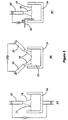
- a plasma system 10 comprising a transferred arc plasma reactor 12 insulated with an insulating material 13 such as alumina felt, a quench tube 14 , and a powder collection unit 16 .
- Reactor 12 is coupled to a power supply 11 , which is itself coupled to a control panel 15 .
- a supply control unit 19 is also provided for controlling the supply of gases and water in reactor 12 .
- a heat exchanger 21 may optionally be inserted between unit 16 and quench tube 14 to further lower the temperature of the powder before collecting it.
- a feeder 23 is provided to feed the material inside plasma chamber 17 .
- FIG. 2 illustrates the interior of plasma reactor 12 , which comprises a plasma chamber 17 .
- An arc 18 is struck between an electrode 33 , preferably non-consumable, located inside torch 20 and material 22 contained in a ceramic crucible 24 .
- a heated diluting gas preferably argon, helium, hydrogen, nitrogen, ammonia, methane or mixtures thereof, is injected through a pipe 28 into chamber 17 to transport the vapor from chamber 17 into quench tube 14 via at least one exit port 30 , powder condensation occurring inside quench tube 14 .
- the powder product exiting the quench tube 14 can be recovered in any suitable solid/gas or solid/liquid separator, such as a particle filtration unit, a scrubber or the like.
- the energy required for vaporizing or decomposing material 22 is supplied by arc 18 maintained between material 22, which is partly or completely liquefied in crucible 24 , and electrode 33 .
- At least one diluting gas is continuously or semi-continuously injected into plasma chamber 17 in addition to the feed gas of plasma torch 20 , this at least one diluting gas being heated to a temperature at least higher than 1000 K, to minimize localized condensation of the vapor.
- Electrode 33 acts as the cathode and liquid material 22 acts as the anode.
- a reversed polarity configuration is highly advantageous when high operating currents are used because the erosion of electrode 33 is drastically reduced when it acts as the anode.
- Preferred arc lengths are from about 2 to 20 cm, but the operator, depending on the material to be produced, can vary the length at will.
- Pressure inside chamber 17 is preferably maintained between 0.2 - 2.0 atm, the most preferred operating pressure being 0.8 - 1.2 atm.
- Figure 3 illustrates various alternative transferred arc arrangements inside the plasma chamber.
- Figure 3A illustrates a preferred crucible arrangement when the latter is conductive.
- Figures 3B and 3C illustrate configurations wherein an auxiliary electrode 32 is used. Such configuration is suitable when the electrical conductivity of crucible 24 is not efficient, or when the crucible is not conductive at all. It should be noted that an auxiliary electrode may be used even when the crucible is electrically conductive at the operating temperature.
- the auxiliary electrode connection 32 may or may not be in direct contact with material 22 .
- the direct contact to material 22 can be either from the top ( Figure 3C), bottom or side.
- auxiliary electrode 32 can be a plasma torch, as per Figure 3B, a water-cooled probe or the feed material.
- Preferred materials of construction for crucible 24 include high melting point materials such as graphite, carbides such as tantalum carbide, silicon carbide, titanium carbide etc.; oxides such as magnesia, alumina, zirconia etc.; nitrides such as titanium nitride, tantalum nitride, zirconium nitride, boron nitride etc.; borides such as titanium diboride, tantalum diboride, zirconium diboride etc.; as well as refractory metals such as tungsten, tantalum, molybdenum, niobium etc.
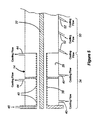
- Figure 4 illustrates a preferred embodiment of a quench tube used in the method according to the present invention.
- the vaporized or decomposed material exits chamber 17 in the form of vapor combined with the diluting gas and the plasma gas, and enters into the first section 34 of quench tube 14 .
- First section 34 allows an indirect controlled cooling or heating of the vapor to nucleate the desired product and control the particle growth and crystallization.
- the indirect heating or cooling can be done using a heating or cooling fluid that is circulated in channel 29 which is formed by the inner surface of an external coaxial tube 36 and the external surface of tube 38 .
- Tube 36 can also be replaced or combined with one or more heating or cooling elements 40 also surrounding tube 38 throughout part or all of its length.
- the length of section 34 can be varied depending on the size of particles required, the flow rate of the diluting gas, the properties desired for the powders etc.
- Tube 36 includes at least one inlet 42 and an at least one outlet 44 to allow fluid circulation therein.
- the reagent may be introduced in the form of a hot reactive gas at one or more points in the first section 34 , for example through an inlet 46 .
- reactive gases include nitrogen, hydrogen, ammonia, methane, oxygen, water, air, carbon monoxide or mixtures thereof.
- the hot reactive gas is also injected at a temperature preferably close to the temperature of the vapor exiting the plasma reactor, or at least higher than 1000 K, to minimize direct cooling of the vapor. Most preferably, the temperature of the injected hot reactive gas is higher than or at least equal to the temperature of the vapor exiting chamber 17 .
- the inner tube of the quench tube should be constructed from a material that can support the temperature of the vapor exiting the plasma chamber. A preferred material is graphite.
- Direct cooling is performed by injecting a fluid, whether liquid or gaseous, directly onto the vapor and/or powder particles through at least one inlet 52 .
- gases for direct cooling of the vapor and the powder particles include argon, nitrogen, helium, ammonia, methane, oxygen, air, carbon monoxide, carbon dioxide or mixtures thereof.
- Preferred liquids include water, methanol, ethanol or mixtures thereof, which are typically injected as a spray.
- the cross-section of the inner tube 38 can be any shape.
- tube 38 is an annular design with the vapor flowing through the annular gap. This embodiment is illustrated in Figure 5 wherein an elongated body 27 is provided inside tube 38 to form a channel between the inner surface of body 38 and the external surface of body 27 .
- Fine metal powder production was carried out using a transferred arc thermal plasma system as illustrated in Figure 1 comprising a reactor as illustrated in Figure 2, and a quench tube as illustrated in Figure 4.
- a transferred arc thermal plasma system as illustrated in Figure 1 comprising a reactor as illustrated in Figure 2, and a quench tube as illustrated in Figure 4.
- any conventional plasma torch can be used.
- the crucible can be graphite or any suitable ceramic.
- the material to be vaporized was fed into the crucible in the form of pellets or shots through a port in the upper section of the plasma chamber.
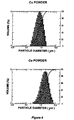
- Fine copper powders with controlled mean particle size and distribution were produced.
- Tests 1 and 2 the control of mean particle size is demonstrated using different quench tube operating conditions.
- the transferred arc reactor conditions are substantially similar.
- a mean particle size of 0.78 ⁇ m was obtained in Test 1 and 1.74 ⁇ m in Test 2.
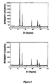
- Fine nickel powders with controlled crystallinity were produced.
- Tests 4 and 5 the control of crystallinity is demonstrated using different quench tube operating conditions. The reactor conditions were substantially the same.
- the maximum peak count for the nickel powder produced during Test 4 was 24800 compared to 9300 for the nickel powder produced during Test 5.
Landscapes
- Chemical & Material Sciences (AREA)
- Organic Chemistry (AREA)
- Chemical Kinetics & Catalysis (AREA)
- Physics & Mathematics (AREA)
- Engineering & Computer Science (AREA)
- Plasma & Fusion (AREA)
- Manufacture Of Metal Powder And Suspensions Thereof (AREA)
- Physical Or Chemical Processes And Apparatus (AREA)
- Powder Metallurgy (AREA)
- Discharge Heating (AREA)
Claims (12)
- Procédé pour la production de poudres fines et ultra-fines avec un système de plasma à arc transféré, le procédé comprenant les étapes consistant à :fournir un matériel à vaporiser ou à décomposer dans un réacteur à plasma ;fournir un gaz d'alimentation de torche à plasma ;amorcer un arc entre le matériau et une électrode pour générer un plasma ayant une température suffisamment élevée pour vaporiser ou décomposer le matériau et former une vapeur de celui-ci ;injecter un gaz de dilution qui est chauffé à une température d'au moins 1 000 K dans le réacteur à plasma, le gaz de dilution étant injecté à un emplacement qui est physiquement séparé du gaz d'alimentation de la torche à plasma ;transporter la vapeur par les moyens du gaz plasma ou du gaz de dilution dans un tube de refroidissement dans lequel la vapeur est condensée et une formation de poudre a lieu, le tube de refroidissement comprenant :une première section pour refroidir ou chauffer indirectement la vapeur et toute particule présente à l'intérieur de celle-ci, pour contrôler substantiellement la croissance et la cristallisation des particules ; etune seconde section couplée à la première section pour refroidir directement la vapeur et toute particule présente à l'intérieur de celle-ci ; etcollecter et facultativement filtrer les particules de poudre dans une unité de stockage.
- Procédé selon la revendication 1, dans lequel le tube de refroidissement est un corps allongé substantiellement tubulaire.
- Procédé selon la revendication 1, dans lequel le matériau comprend des métaux, des alliages, des céramiques et des composites.
- Procédé selon la revendication 1, dans lequel le matériau vaporisé ou décomposé est l'anode et l'électrode est la cathode et n'est pas consommable.
- Procédé selon la revendication 1, dans lequel le matériau est fourni dans un creuset électroconducteur.
- Procédé selon la revendication 1, dans lequel le matériau est apporté dans le réacteur à plasma sous la forme de particules solides, de câble, de tige, de liquide, ou de mélanges de ceci.
- Procédé selon la revendication 6, dans lequel le creuset est fabriqué à partir de graphite, d'un carbure, d'un oxyde, d'un nitrure, d'un borure ou d'un métal réfractaire.
- Procédé selon la revendication 2, dans lequel le refroidissement ou le chauffage indirect est réalisé en faisant circuler un fluide de refroidissement ou un fluide chauffant dans un canal autour du corps.
- Procédé selon la revendication 1, dans lequel un réactif est injecté sous la forme d'un gaz chaud dans la première section à partir d'au moins une entrée.
- Procédé selon la revendication 1, dans lequel le refroidissement direct est réalisé en injectant un fluide de refroidissement directement dans la vapeur.
- Procédé selon la revendication 1, dans lequel le matériau à vaporiser est un métal qui est continuellement alimenté dans un creuset électroconducteur à l'intérieur d'un réacteur à plasma ; et le tube de refroidissement comprend :une première section comprenant un corps tubulaire allongé pour refroidir ou chauffer indirectement la vapeur et toute particule présente à l'intérieur de celle-ci, pour substantiellement contrôler la croissance et la cristallisation des particules ; la vapeur passant dans l'intérieur du corps, etune seconde section couplée à la première section pour refroidir directement la vapeur et toute particule présente à l'intérieur de celle-ci en injectant un fluide de refroidissement directement dans la vapeur.
- Procédé selon la revendication 11, dans lequel le métal comprend l'argent, l'or, le cadmium, le cobalt, le cuivre, le fer, le molybdène, le nickel, le niobium, le palladium, le platine, le rhodium, le ruthénium, le tantale, le titane, le tungstène, le zirconium et des alliages de ceux-ci.
Applications Claiming Priority (3)
| Application Number | Priority Date | Filing Date | Title |
|---|---|---|---|
| US09/136,043 US6379419B1 (en) | 1998-08-18 | 1998-08-18 | Method and transferred arc plasma system for production of fine and ultrafine powders |
| PCT/CA1999/000759 WO2000010756A1 (fr) | 1998-08-18 | 1999-08-16 | Procede et systeme de plasma a arc transfere pour la production de poudres fines et ultra-fines |
| US136043 | 2002-04-30 |
Publications (2)
| Publication Number | Publication Date |
|---|---|
| EP1115523A1 EP1115523A1 (fr) | 2001-07-18 |
| EP1115523B1 true EP1115523B1 (fr) | 2003-05-14 |
Family
ID=22470991
Family Applications (1)
| Application Number | Title | Priority Date | Filing Date |
|---|---|---|---|
| EP99938107A Expired - Lifetime EP1115523B1 (fr) | 1998-08-18 | 1999-08-16 | Procede et systeme de plasma a arc transfere pour la production de poudres fines et ultra-fines |
Country Status (9)
| Country | Link |
|---|---|
| US (1) | US6379419B1 (fr) |
| EP (1) | EP1115523B1 (fr) |
| JP (3) | JP3541939B2 (fr) |
| KR (1) | KR100594562B1 (fr) |
| AT (1) | ATE240177T1 (fr) |
| AU (1) | AU5275299A (fr) |
| CA (1) | CA2340669C (fr) |
| DE (1) | DE69907933T2 (fr) |
| WO (1) | WO2000010756A1 (fr) |
Cited By (3)
| Publication number | Priority date | Publication date | Assignee | Title |
|---|---|---|---|---|
| RU2455119C2 (ru) * | 2010-08-27 | 2012-07-10 | Алексей Александрович Калачев | Способ получения наночастиц |
| RU2460816C1 (ru) * | 2011-05-20 | 2012-09-10 | Федеральное государственное бюджетное образовательное учреждение высшего профессионального образования "Казанский национальный исследовательский технический университет им. А.Н.Туполева - КАИ" (КНИТУ-КАИ) | Способ получения порошкового материала на основе меди |
| CN102873323A (zh) * | 2012-11-01 | 2013-01-16 | 泰克科技(苏州)有限公司 | 电子钽粉性能改善装置 |
Families Citing this family (114)
| Publication number | Priority date | Publication date | Assignee | Title |
|---|---|---|---|---|
| US7576296B2 (en) * | 1995-03-14 | 2009-08-18 | Battelle Energy Alliance, Llc | Thermal synthesis apparatus |
| US6972115B1 (en) | 1999-09-03 | 2005-12-06 | American Inter-Metallics, Inc. | Apparatus and methods for the production of powders |
| KR100743844B1 (ko) * | 1999-12-01 | 2007-08-02 | 도와 마이닝 가부시끼가이샤 | 구리 분말 및 구리 분말의 제조 방법 |
| AU2906401A (en) * | 1999-12-21 | 2001-07-03 | Bechtel Bwxt Idaho, Llc | Hydrogen and elemental carbon production from natural gas and other hydrocarbons |
| AU2001232063A1 (en) * | 2000-02-10 | 2001-08-20 | Tetronics Limited | Plasma arc reactor for the production of fine powders |
| CN101284312B (zh) * | 2000-02-18 | 2012-06-13 | 加拿大电子学粉末公司 | 一种通过传递电弧等离子系统生产镍粉末的方法 |
| WO2002005969A2 (fr) * | 2000-07-19 | 2002-01-24 | Regents Of The University Of Minnesota | Appareil et procede de synthese de films et de revetements au moyen d'un depot par faisceau de particules focalise |
| US6468497B1 (en) * | 2000-11-09 | 2002-10-22 | Cyprus Amax Minerals Company | Method for producing nano-particles of molybdenum oxide |
| US7572430B2 (en) * | 2000-11-09 | 2009-08-11 | Cyprus Amax Minerals Company | Method for producing nano-particles |
| AUPR186200A0 (en) * | 2000-12-04 | 2001-01-04 | Tesla Group Holdings Pty Limited | Plasma reduction processing of materials |
| US7442227B2 (en) | 2001-10-09 | 2008-10-28 | Washington Unniversity | Tightly agglomerated non-oxide particles and method for producing the same |
| US7097691B2 (en) * | 2001-11-06 | 2006-08-29 | Cyprus Amax Minerals Company | Method for producing pigment nano-particles |
| US6688494B2 (en) * | 2001-12-20 | 2004-02-10 | Cima Nanotech, Inc. | Process for the manufacture of metal nanoparticle |
| US6755886B2 (en) * | 2002-04-18 | 2004-06-29 | The Regents Of The University Of California | Method for producing metallic microparticles |
| US6902601B2 (en) | 2002-09-12 | 2005-06-07 | Millennium Inorganic Chemicals, Inc. | Method of making elemental materials and alloys |
| US6868896B2 (en) * | 2002-09-20 | 2005-03-22 | Edward Scott Jackson | Method and apparatus for melting titanium using a combination of plasma torches and direct arc electrodes |
| US7794629B2 (en) * | 2003-11-25 | 2010-09-14 | Qinetiq Limited | Composite materials |
| US7494527B2 (en) * | 2004-01-26 | 2009-02-24 | Tekna Plasma Systems Inc. | Process for plasma synthesis of rhenium nano and micro powders, and for coatings and near net shape deposits thereof and apparatus therefor |
| US7384448B2 (en) * | 2004-02-16 | 2008-06-10 | Climax Engineered Materials, Llc | Method and apparatus for producing nano-particles of silver |
| JP2005289776A (ja) * | 2004-04-05 | 2005-10-20 | Canon Inc | 結晶製造方法および結晶製造装置 |
| JP3938770B2 (ja) * | 2004-04-16 | 2007-06-27 | Tdk株式会社 | ニッケル粉の製造方法とニッケル粉の製造装置とニッケル粉製造用坩堝 |
| JP5628472B2 (ja) * | 2004-04-19 | 2014-11-19 | エスディーシーマテリアルズ, インコーポレイテッド | 気相合成による高スループットの材料発見方法 |
| US7465430B2 (en) * | 2004-07-20 | 2008-12-16 | E. I. Du Pont De Nemours And Company | Apparatus for making metal oxide nanopowder |
| US7708975B2 (en) * | 2004-07-20 | 2010-05-04 | E.I. Du Pont De Nemours And Company | Process for making metal oxide nanoparticles |
| US7297619B2 (en) * | 2004-08-24 | 2007-11-20 | California Institute Of Technology | System and method for making nanoparticles using atmospheric-pressure plasma microreactor |
| EP1810001A4 (fr) | 2004-10-08 | 2008-08-27 | Sdc Materials Llc | Appareil et procede d'echantillonnage et de collecte de poudres s'ecoulant dans un flux de gaz |
| US7476851B2 (en) * | 2004-11-12 | 2009-01-13 | Regents Of The University Of Minnesota | Aerodynamic focusing of nanoparticle or cluster beams |
| US7354561B2 (en) * | 2004-11-17 | 2008-04-08 | Battelle Energy Alliance, Llc | Chemical reactor and method for chemically converting a first material into a second material |
| WO2006079213A1 (fr) | 2005-01-28 | 2006-08-03 | Tekna Plasma Systems Inc. | Synthese de nanopoudres par plasma a induction |
| US8079838B2 (en) * | 2005-03-16 | 2011-12-20 | Horiba, Ltd. | Pure particle generator |
| DE102005028463A1 (de) * | 2005-06-17 | 2006-12-28 | Basf Ag | Verfahren zur Herstellung von nanopartikulären Lanthanoid/Bor-Verbindungen von nanopartikuläre Lanthanoid/Bor-Verbindungen enthaltenden Feststoffgemischen |
| CN100431748C (zh) * | 2005-07-27 | 2008-11-12 | 北京工业大学 | 稀土元素钆的纳米颗粒及纳米晶块体材料的制备方法 |
| US8268405B2 (en) * | 2005-08-23 | 2012-09-18 | Uwm Research Foundation, Inc. | Controlled decoration of carbon nanotubes with aerosol nanoparticles |
| US8240190B2 (en) * | 2005-08-23 | 2012-08-14 | Uwm Research Foundation, Inc. | Ambient-temperature gas sensor |
| CA2581806C (fr) * | 2006-03-08 | 2012-06-26 | Tekna Plasma Systems Inc. | Synthese plasmique de nanopoudres |
| KR100840229B1 (ko) | 2006-09-08 | 2008-06-23 | 재단법인 포항산업과학연구원 | 초미세 솔더 분말, 초미세 솔더 분말의 제조방법 및 그제조장치 |
| US7736421B2 (en) * | 2006-10-10 | 2010-06-15 | Aerosol Dynamics Inc. | High saturation ratio water condensation device and method |
| JP5052291B2 (ja) | 2006-11-02 | 2012-10-17 | 株式会社日清製粉グループ本社 | 合金超微粒子、およびその製造方法 |
| KR100788413B1 (ko) | 2007-03-13 | 2007-12-24 | 호서대학교 산학협력단 | 열플라즈마를 이용한 나노 복합 분말 제조 방법 |
| US8142619B2 (en) | 2007-05-11 | 2012-03-27 | Sdc Materials Inc. | Shape of cone and air input annulus |
| US9630162B1 (en) * | 2007-10-09 | 2017-04-25 | University Of Louisville Research Foundation, Inc. | Reactor and method for production of nanostructures |
| US8575059B1 (en) | 2007-10-15 | 2013-11-05 | SDCmaterials, Inc. | Method and system for forming plug and play metal compound catalysts |
| EP2107862B1 (fr) | 2008-04-03 | 2015-09-02 | Maicom Quarz GmbH | Procédé et dispositif destinés au traitement de matériaux de dispersion |
| USD627900S1 (en) | 2008-05-07 | 2010-11-23 | SDCmaterials, Inc. | Glove box |
| KR101009656B1 (ko) | 2008-09-17 | 2011-01-19 | 희성금속 주식회사 | 초미세 귀금속 분말 제조방법 |
| WO2010049382A1 (fr) * | 2008-10-27 | 2010-05-06 | Basf Se | Procédé de préparation d'une suspension de borures métalliques nanoparticulaires |
| KR101024971B1 (ko) | 2008-12-12 | 2011-03-25 | 희성금속 주식회사 | 열플라즈마를 이용한 귀금속 분말 및 귀금속 타겟 제조방법 |
| US9516734B2 (en) | 2009-03-24 | 2016-12-06 | Tekna Plasma Systems Inc. | Plasma reactor for the synthesis of nanopowders and materials processing |
| US8591821B2 (en) | 2009-04-23 | 2013-11-26 | Battelle Energy Alliance, Llc | Combustion flame-plasma hybrid reactor systems, and chemical reactant sources |
| KR100943453B1 (ko) * | 2009-08-18 | 2010-02-22 | 이대식 | 초미세 금속분말 제조 장치 및 방법, 이에 사용되는 금속증발장치 |
| KR101134501B1 (ko) * | 2009-12-07 | 2012-04-13 | 주식회사 풍산 | 열플라즈마를 이용한 고순도 구리분말의 제조방법 |
| US9126191B2 (en) | 2009-12-15 | 2015-09-08 | SDCmaterials, Inc. | Advanced catalysts for automotive applications |
| US9149797B2 (en) | 2009-12-15 | 2015-10-06 | SDCmaterials, Inc. | Catalyst production method and system |
| US8557727B2 (en) * | 2009-12-15 | 2013-10-15 | SDCmaterials, Inc. | Method of forming a catalyst with inhibited mobility of nano-active material |
| US8545652B1 (en) | 2009-12-15 | 2013-10-01 | SDCmaterials, Inc. | Impact resistant material |
| US8470112B1 (en) | 2009-12-15 | 2013-06-25 | SDCmaterials, Inc. | Workflow for novel composite materials |
| US9090475B1 (en) | 2009-12-15 | 2015-07-28 | SDCmaterials, Inc. | In situ oxide removal, dispersal and drying for silicon SiO2 |
| US8652992B2 (en) | 2009-12-15 | 2014-02-18 | SDCmaterials, Inc. | Pinning and affixing nano-active material |
| US8803025B2 (en) | 2009-12-15 | 2014-08-12 | SDCmaterials, Inc. | Non-plugging D.C. plasma gun |
| WO2011119494A1 (fr) | 2010-03-22 | 2011-09-29 | The Regents Of The University Of California | Procédé et dispositif pour synthétiser des nanotubes de nitrure de bore et des nanoparticules associées |
| KR101175676B1 (ko) * | 2010-03-25 | 2012-08-22 | 희성금속 주식회사 | 폐 루테늄(Ru) 타겟을 이용한 고순도화 및 미세화된 루테늄(Ru)분말 제조법 |
| KR101193683B1 (ko) | 2010-03-29 | 2012-10-22 | 현대제철 주식회사 | 지르코늄 코어드 와이어 투입법을 이용한 지르코늄 함유 철계 합금 제조 방법 및 그 제조 장치 |
| CN102166654B (zh) * | 2010-12-30 | 2015-11-25 | 广东高鑫科技股份有限公司 | 高效镍-石墨粉体的制备方法及其专用装置 |
| US8669202B2 (en) | 2011-02-23 | 2014-03-11 | SDCmaterials, Inc. | Wet chemical and plasma methods of forming stable PtPd catalysts |
| KR101285284B1 (ko) * | 2011-04-26 | 2013-07-11 | 희성금속 주식회사 | 폐 루테늄(Ru) 타겟을 이용한 초고순도 루테늄(Ru) 분말 및 타겟의 제조방법 |
| CN102211197B (zh) * | 2011-05-06 | 2014-06-04 | 宁波广博纳米新材料股份有限公司 | 金属蒸发装置及用该装置制备超微细金属粉末的方法 |
| JP5824906B2 (ja) * | 2011-06-24 | 2015-12-02 | 昭栄化学工業株式会社 | 金属粉末製造用プラズマ装置及び金属粉末製造方法 |
| KR20140071364A (ko) | 2011-08-19 | 2014-06-11 | 에스디씨머티리얼스, 인코포레이티드 | 촉매작용에 사용하기 위한 코팅 기판 및 촉매 변환기 및 기판을 워시코트 조성물로 코팅하는 방법 |
| JP5821579B2 (ja) * | 2011-12-01 | 2015-11-24 | 昭栄化学工業株式会社 | 金属粉末製造用プラズマ装置 |
| CA2855579C (fr) * | 2011-12-06 | 2019-10-29 | Shoei Chemical Inc. | Dispositif a plasma pour production d'une poudre metallique |
| JP5817636B2 (ja) * | 2012-04-20 | 2015-11-18 | 昭栄化学工業株式会社 | 金属粉末の製造方法 |
| US20150147257A1 (en) * | 2012-06-05 | 2015-05-28 | Dow Corning Corporation | Fluid capture of nanoparticles |
| CN102950292B (zh) * | 2012-10-15 | 2015-07-08 | 宁波广博纳米新材料股份有限公司 | 亚微米级铜锰镍合金粉的生产方法 |
| CN102950290B (zh) * | 2012-10-15 | 2014-11-26 | 宁波广博纳米新材料股份有限公司 | 纳米级镍锰合金粉的生产方法 |
| CN102950289B (zh) * | 2012-10-15 | 2014-10-15 | 宁波广博纳米新材料股份有限公司 | 纳米级铜锰合金粉的生产方法 |
| CN102950291B (zh) * | 2012-10-15 | 2015-02-11 | 宁波广博纳米新材料股份有限公司 | 亚微米级锡铜合金粉的生产方法 |
| CN102950293B (zh) * | 2012-10-15 | 2015-01-07 | 宁波广博纳米新材料股份有限公司 | 纳米铝粉的生产方法 |
| CN103008673B (zh) * | 2012-11-07 | 2014-08-06 | 宁波广博纳米新材料股份有限公司 | 蒸发冷凝法制备含硫镍粉的方法 |
| JP6089186B2 (ja) * | 2012-11-12 | 2017-03-08 | 国立大学法人弘前大学 | 超微細粉末、高強度鋼焼結体及びそれらの製造方法 |
| US9156025B2 (en) | 2012-11-21 | 2015-10-13 | SDCmaterials, Inc. | Three-way catalytic converter using nanoparticles |
| US9511352B2 (en) | 2012-11-21 | 2016-12-06 | SDCmaterials, Inc. | Three-way catalytic converter using nanoparticles |
| KR20150003580A (ko) * | 2013-07-01 | 2015-01-09 | 희성금속 주식회사 | 루테늄 분말 및 루테늄 타겟의 제조방법 |
| EP3024571B1 (fr) | 2013-07-25 | 2020-05-27 | Umicore AG & Co. KG | Revêtements catalytiques et substrats revêtus pour convertisseurs catalytiques |
| CN103537703B (zh) * | 2013-09-12 | 2017-04-12 | 江苏博迁新材料股份有限公司 | 一种内回流式除垃圾方法 |
| MX2016004759A (es) | 2013-10-22 | 2016-07-26 | Sdcmaterials Inc | Composiciones para trampas de oxidos de nitrogeno (nox) pobres. |
| US9427732B2 (en) | 2013-10-22 | 2016-08-30 | SDCmaterials, Inc. | Catalyst design for heavy-duty diesel combustion engines |
| CN106470752A (zh) | 2014-03-21 | 2017-03-01 | Sdc材料公司 | 用于被动nox吸附(pna)系统的组合物 |
| CN104084595B (zh) * | 2014-07-11 | 2016-08-24 | 湖南娄底华星锑业有限公司 | 一种锑粉生产系统 |
| DE102014220817B4 (de) | 2014-10-14 | 2021-02-04 | Universität Duisburg-Essen | Lichtbogenreaktor und Verfahren zur Herstellung von Nanopartikeln |
| CN104722764B (zh) * | 2015-03-11 | 2017-01-25 | 江永斌 | 循环冷却的金属粉体蒸发制取装置 |
| CN104690266A (zh) * | 2015-03-18 | 2015-06-10 | 宁波广博纳米新材料股份有限公司 | 用于制备晶片电阻器正面、背面电极的铜锰合金粉 |
| JP5954470B2 (ja) * | 2015-06-26 | 2016-07-20 | 昭栄化学工業株式会社 | 金属粉末製造用プラズマ装置及び金属粉末製造方法 |
| KR102091143B1 (ko) | 2015-10-19 | 2020-03-20 | 스미토모 긴조쿠 고잔 가부시키가이샤 | 니켈 분말의 제조 방법 |
| CN105252012B (zh) * | 2015-11-18 | 2017-02-08 | 长春工业大学 | 一种多电极等离子弧连续制造金属粉末的装置及方法 |
| JP6573563B2 (ja) | 2016-03-18 | 2019-09-11 | 住友金属鉱山株式会社 | ニッケル粉末、ニッケル粉末の製造方法、およびニッケル粉末を用いた内部電極ペーストならびに電子部品 |
| CN105598460B (zh) * | 2016-03-21 | 2018-03-06 | 台州市金博超导纳米材料科技有限公司 | 用于制造微纳米级金属粉末的高温蒸发器 |
| JP6729719B2 (ja) | 2016-12-05 | 2020-07-22 | 住友金属鉱山株式会社 | ニッケル粉末の製造方法 |
| JP6920676B2 (ja) * | 2017-04-19 | 2021-08-18 | パナソニックIpマネジメント株式会社 | 微粒子製造装置および微粒子製造方法 |
| CN107030292A (zh) * | 2017-05-03 | 2017-08-11 | 江苏天楹环保能源成套设备有限公司 | 一种多级冷却制备金属粉末的等离子体雾化装置 |
| JP7194544B2 (ja) * | 2017-10-03 | 2022-12-22 | 三井金属鉱業株式会社 | 粒子の製造方法 |
| CN108130524A (zh) * | 2017-12-22 | 2018-06-08 | 中国科学院电工研究所 | 等离子体射流沉积薄膜装置及浅化表面陷阱能级的方法 |
| US10612111B2 (en) * | 2018-08-21 | 2020-04-07 | Robert Ten | Method and apparatus for extracting high-purity gold from ore |
| KR102141225B1 (ko) * | 2018-08-29 | 2020-08-04 | 한국생산기술연구원 | 온도급감장치를 구비한 열플라즈마 토치 및 이를 이용한 금속 나노 분말 가공장치. |
| WO2021020522A1 (fr) | 2019-07-31 | 2021-02-04 | 住友金属鉱山株式会社 | Poudre de nickel et procédé de production de poudre de nickel |
| EP4056301A4 (fr) * | 2019-11-07 | 2023-12-20 | Shenzhen Aerospace Science Advanced Materials Co., Ltd | Nouvelle poudre sphérique et procédé de préparation associé |
| RU2746197C1 (ru) * | 2020-05-11 | 2021-04-08 | Федеральное государственное бюджетное образовательное учреждение высшего образования "Пензенский государственный университет" | Способ получения мелкодисперсного порошка тугоплавкого материала |
| RU2746673C1 (ru) * | 2020-10-09 | 2021-04-19 | федеральное государственное автономное образовательное учреждение высшего образования «Национальный исследовательский Томский политехнический университет» | СПОСОБ ПОЛУЧЕНИЯ ПОРОШКА, СОДЕРЖАЩЕГО ОДНОФАЗНЫЙ ВЫСОКОЭНТРОПИЙНЫЙ КАРБИД СОСТАВА Ti-Nb-Zr-Hf-Ta-C С КУБИЧЕСКОЙ РЕШЕТКОЙ |
| CN214260700U (zh) * | 2021-01-08 | 2021-09-24 | 江苏博迁新材料股份有限公司 | 一种使用等离子转移弧加热的高温蒸发器 |
| WO2022156229A1 (fr) * | 2021-01-25 | 2022-07-28 | 钟笔 | Dispositif de commande pour commander la formation de particules de poudre ultrafines |
| CN216421070U (zh) * | 2021-10-19 | 2022-05-03 | 江苏博迁新材料股份有限公司 | 一种物理气相法制备超细粉体材料用的金属蒸气成核装置 |
| KR102572728B1 (ko) * | 2021-11-19 | 2023-08-31 | 한국생산기술연구원 | 금속분말 제조장치 및 이를 이용한 금속분말 제조방법 |
| RU210733U1 (ru) * | 2022-01-28 | 2022-04-28 | Федеральное государственное автономное образовательное учреждение высшего образования "Национальный исследовательский Томский политехнический университет" | Устройство для получения порошка на основе карбида бора |
| JP2023183703A (ja) | 2022-06-16 | 2023-12-28 | 昭栄化学工業株式会社 | 金属粉末の製造方法および金属粉末の製造装置 |
| KR102465825B1 (ko) * | 2022-09-06 | 2022-11-09 | 이용복 | 열플라즈마를 이용한 금속분말 제조장치 및 그 제조방법 |
Family Cites Families (15)
| Publication number | Priority date | Publication date | Assignee | Title |
|---|---|---|---|---|
| DE269157C (fr) | 1911-12-12 | |||
| US4076640A (en) * | 1975-02-24 | 1978-02-28 | Xerox Corporation | Preparation of spheroidized particles |
| GB2002208B (en) * | 1977-08-01 | 1982-04-28 | Thermo Electron Corp | Process of and apparatus for producing a particulate product from a feed material |
| US4376470A (en) | 1980-11-06 | 1983-03-15 | Little Giant Industries, Inc. | Fiberglass ladder |
| US4376740A (en) | 1981-01-05 | 1983-03-15 | National Research Institute For Metals | Process for production fine metal particles |
| DD269157A1 (de) * | 1987-12-28 | 1989-06-21 | Akad Wissenschaften Ddr | Plasmareaktor fuer die pyrolyse hochviskoser, teerartiger, kohlenwasserstoffhaltiger produkte |
| US4990179A (en) * | 1990-04-23 | 1991-02-05 | Fmc Corporation | Process for increasing the life of carbon crucibles in plasma furnaces |
| US5147448A (en) * | 1990-10-01 | 1992-09-15 | Nuclear Metals, Inc. | Techniques for producing fine metal powder |
| WO1992014576A1 (fr) * | 1991-02-22 | 1992-09-03 | Idaho Research Foundation | Production plasmatique de carbures ceramiques ultrafins |
| JP3245965B2 (ja) * | 1992-05-29 | 2002-01-15 | 株式会社村田製作所 | 銅粉末の製造方法 |
| US5460701A (en) * | 1993-07-27 | 1995-10-24 | Nanophase Technologies Corporation | Method of making nanostructured materials |
| US5514350A (en) | 1994-04-22 | 1996-05-07 | Rutgers, The State University Of New Jersey | Apparatus for making nanostructured ceramic powders and whiskers |
| US5855642A (en) * | 1996-06-17 | 1999-01-05 | Starmet Corporation | System and method for producing fine metallic and ceramic powders |
| US5782952A (en) * | 1996-08-30 | 1998-07-21 | Massachusetts Institute Of Technology | Method for production of magnesium |
| JPH10102109A (ja) * | 1996-09-30 | 1998-04-21 | Tanaka Kikinzoku Kogyo Kk | ニッケル粉末の製造方法 |
-
1998
- 1998-08-18 US US09/136,043 patent/US6379419B1/en not_active Expired - Lifetime
-
1999
- 1999-08-16 KR KR1020017002087A patent/KR100594562B1/ko not_active IP Right Cessation
- 1999-08-16 AT AT99938107T patent/ATE240177T1/de not_active IP Right Cessation
- 1999-08-16 EP EP99938107A patent/EP1115523B1/fr not_active Expired - Lifetime
- 1999-08-16 AU AU52752/99A patent/AU5275299A/en not_active Abandoned
- 1999-08-16 DE DE69907933T patent/DE69907933T2/de not_active Expired - Lifetime
- 1999-08-16 JP JP2000566062A patent/JP3541939B2/ja not_active Expired - Lifetime
- 1999-08-16 WO PCT/CA1999/000759 patent/WO2000010756A1/fr active IP Right Grant
- 1999-08-16 CA CA002340669A patent/CA2340669C/fr not_active Expired - Lifetime
-
2003
- 2003-10-27 JP JP2003366114A patent/JP2004036005A/ja active Pending
-
2005
- 2005-02-10 JP JP2005034922A patent/JP2005163188A/ja active Pending
Cited By (3)
| Publication number | Priority date | Publication date | Assignee | Title |
|---|---|---|---|---|
| RU2455119C2 (ru) * | 2010-08-27 | 2012-07-10 | Алексей Александрович Калачев | Способ получения наночастиц |
| RU2460816C1 (ru) * | 2011-05-20 | 2012-09-10 | Федеральное государственное бюджетное образовательное учреждение высшего профессионального образования "Казанский национальный исследовательский технический университет им. А.Н.Туполева - КАИ" (КНИТУ-КАИ) | Способ получения порошкового материала на основе меди |
| CN102873323A (zh) * | 2012-11-01 | 2013-01-16 | 泰克科技(苏州)有限公司 | 电子钽粉性能改善装置 |
Also Published As
| Publication number | Publication date |
|---|---|
| EP1115523A1 (fr) | 2001-07-18 |
| JP2005163188A (ja) | 2005-06-23 |
| AU5275299A (en) | 2000-03-14 |
| WO2000010756A1 (fr) | 2000-03-02 |
| JP3541939B2 (ja) | 2004-07-14 |
| DE69907933D1 (de) | 2003-06-18 |
| JP2002530521A (ja) | 2002-09-17 |
| KR100594562B1 (ko) | 2006-06-30 |
| US6379419B1 (en) | 2002-04-30 |
| CA2340669C (fr) | 2009-04-07 |
| KR20010099622A (ko) | 2001-11-09 |
| CA2340669A1 (fr) | 2000-03-02 |
| ATE240177T1 (de) | 2003-05-15 |
| JP2004036005A (ja) | 2004-02-05 |
| DE69907933T2 (de) | 2004-04-01 |
Similar Documents
| Publication | Publication Date | Title |
|---|---|---|
| EP1115523B1 (fr) | Procede et systeme de plasma a arc transfere pour la production de poudres fines et ultra-fines | |
| US8859931B2 (en) | Plasma synthesis of nanopowders | |
| EP0282291B1 (fr) | Procédé de préparation de particules extrêmement fines de métaux, de composés de métal et de céramique, et dispositif utilisé | |
| EP1843834B1 (fr) | Synthese de nanopoudres par plasma a induction | |
| US8092570B2 (en) | Method for producing titanium metal | |
| US9516734B2 (en) | Plasma reactor for the synthesis of nanopowders and materials processing | |
| US4164553A (en) | Plasma arc process for the production of chemical products in power form | |
| WO1993012634A1 (fr) | Dispositif de torche pour processus chimiques | |
| US4335080A (en) | Apparatus for producing selective particle sized oxide | |
| JPS6330062B2 (fr) | ||
| KR20090026512A (ko) | 아크 플라즈마 장치를 이용한 니켈 나노분말의 제조방법 및장치 | |
| WO2009058626A1 (fr) | Cuve de réacteur pour une gazéification au plasma | |
| Ageorges et al. | Synthesis of aluminum nitride in transferred arc plasma furnaces | |
| EP0887133B1 (fr) | Procede de production de poudre metallique et equipement associe | |
| WO1993023331A1 (fr) | Procede de production de fullerenes utilisant du plasma | |
| WO1993002787A1 (fr) | Procede de production de materiaux en poudre ultrafins | |
| CA1099521A (fr) | Procede d'obtention de vanadium | |
| WO1992014576A1 (fr) | Production plasmatique de carbures ceramiques ultrafins | |
| Ananthapadmanabhan et al. | Plasma thermal dissociation of Indian zircon | |
| Pirzada | Silicon carbide synthesis and modeling in a nontransferred arc thermal plasmareactor | |
| Samokhin et al. | Characteristics of heat and mass transfer to the wall of a confined-jet plasma flow reactor in the processes of nanopowder preparation from metals and their compounds | |
| JP2023183703A (ja) | 金属粉末の製造方法および金属粉末の製造装置 | |
| Venkatramani | Thermal plasmas in material processing | |
| Juhász et al. | Preparation of Raw Materials for Fine Ceramics in Plasmas |
Legal Events
| Date | Code | Title | Description |
|---|---|---|---|
| PUAI | Public reference made under article 153(3) epc to a published international application that has entered the european phase |
Free format text: ORIGINAL CODE: 0009012 |
|
| 17P | Request for examination filed |
Effective date: 20010319 |
|
| AK | Designated contracting states |
Kind code of ref document: A1 Designated state(s): AT BE CH CY DE DK ES FI FR GB GR IE IT LI LU MC NL PT SE |
|
| AX | Request for extension of the european patent |
Free format text: AL;LT;LV;MK;RO;SI |
|
| 17Q | First examination report despatched |
Effective date: 20010831 |
|
| RAP1 | Party data changed (applicant data changed or rights of an application transferred) |
Owner name: CANADIAN ELECTRONIC POWDERS CORPORATION |
|
| GRAH | Despatch of communication of intention to grant a patent |
Free format text: ORIGINAL CODE: EPIDOS IGRA |
|
| GRAH | Despatch of communication of intention to grant a patent |
Free format text: ORIGINAL CODE: EPIDOS IGRA |
|
| GRAA | (expected) grant |
Free format text: ORIGINAL CODE: 0009210 |
|
| AK | Designated contracting states |
Designated state(s): AT BE CH CY DE DK ES FI FR GB GR IE IT LI LU MC NL PT SE |
|
| PG25 | Lapsed in a contracting state [announced via postgrant information from national office to epo] |
Ref country code: NL Free format text: LAPSE BECAUSE OF FAILURE TO SUBMIT A TRANSLATION OF THE DESCRIPTION OR TO PAY THE FEE WITHIN THE PRESCRIBED TIME-LIMIT Effective date: 20030514 Ref country code: LI Free format text: LAPSE BECAUSE OF FAILURE TO SUBMIT A TRANSLATION OF THE DESCRIPTION OR TO PAY THE FEE WITHIN THE PRESCRIBED TIME-LIMIT Effective date: 20030514 Ref country code: IT Free format text: LAPSE BECAUSE OF FAILURE TO SUBMIT A TRANSLATION OF THE DESCRIPTION OR TO PAY THE FEE WITHIN THE PRE;WARNING: LAPSES OF ITALIAN PATENTS WITH EFFECTIVE DATE BEFORE 2007 MAY HAVE OCCURRED AT ANY TIME BEFORE 2007. THE CORRECT EFFECTIVE DATE MAY BE DIFFERENT FROM THE ONE RECORDED.SCRIBED TIME-LIMIT Effective date: 20030514 Ref country code: FI Free format text: LAPSE BECAUSE OF FAILURE TO SUBMIT A TRANSLATION OF THE DESCRIPTION OR TO PAY THE FEE WITHIN THE PRESCRIBED TIME-LIMIT Effective date: 20030514 Ref country code: CH Free format text: LAPSE BECAUSE OF FAILURE TO SUBMIT A TRANSLATION OF THE DESCRIPTION OR TO PAY THE FEE WITHIN THE PRESCRIBED TIME-LIMIT Effective date: 20030514 Ref country code: AT Free format text: LAPSE BECAUSE OF FAILURE TO SUBMIT A TRANSLATION OF THE DESCRIPTION OR TO PAY THE FEE WITHIN THE PRESCRIBED TIME-LIMIT Effective date: 20030514 |
|
| REG | Reference to a national code |
Ref country code: GB Ref legal event code: FG4D |
|
| REG | Reference to a national code |
Ref country code: CH Ref legal event code: EP |
|
| REG | Reference to a national code |
Ref country code: IE Ref legal event code: FG4D |
|
| REF | Corresponds to: |
Ref document number: 69907933 Country of ref document: DE Date of ref document: 20030618 Kind code of ref document: P |
|
| PG25 | Lapsed in a contracting state [announced via postgrant information from national office to epo] |
Ref country code: SE Free format text: LAPSE BECAUSE OF FAILURE TO SUBMIT A TRANSLATION OF THE DESCRIPTION OR TO PAY THE FEE WITHIN THE PRESCRIBED TIME-LIMIT Effective date: 20030814 Ref country code: PT Free format text: LAPSE BECAUSE OF FAILURE TO SUBMIT A TRANSLATION OF THE DESCRIPTION OR TO PAY THE FEE WITHIN THE PRESCRIBED TIME-LIMIT Effective date: 20030814 Ref country code: GR Free format text: LAPSE BECAUSE OF FAILURE TO SUBMIT A TRANSLATION OF THE DESCRIPTION OR TO PAY THE FEE WITHIN THE PRESCRIBED TIME-LIMIT Effective date: 20030814 Ref country code: DK Free format text: LAPSE BECAUSE OF FAILURE TO SUBMIT A TRANSLATION OF THE DESCRIPTION OR TO PAY THE FEE WITHIN THE PRESCRIBED TIME-LIMIT Effective date: 20030814 |
|
| PG25 | Lapsed in a contracting state [announced via postgrant information from national office to epo] |
Ref country code: LU Free format text: LAPSE BECAUSE OF NON-PAYMENT OF DUE FEES Effective date: 20030816 Ref country code: CY Free format text: LAPSE BECAUSE OF FAILURE TO SUBMIT A TRANSLATION OF THE DESCRIPTION OR TO PAY THE FEE WITHIN THE PRESCRIBED TIME-LIMIT Effective date: 20030816 |
|
| PG25 | Lapsed in a contracting state [announced via postgrant information from national office to epo] |
Ref country code: ES Free format text: LAPSE BECAUSE OF FAILURE TO SUBMIT A TRANSLATION OF THE DESCRIPTION OR TO PAY THE FEE WITHIN THE PRESCRIBED TIME-LIMIT Effective date: 20030825 |
|
| PG25 | Lapsed in a contracting state [announced via postgrant information from national office to epo] |
Ref country code: MC Free format text: LAPSE BECAUSE OF NON-PAYMENT OF DUE FEES Effective date: 20030831 |
|
| LTIE | Lt: invalidation of european patent or patent extension |
Effective date: 20030514 |
|
| NLV1 | Nl: lapsed or annulled due to failure to fulfill the requirements of art. 29p and 29m of the patents act | ||
| REG | Reference to a national code |
Ref country code: CH Ref legal event code: PL |
|
| ET | Fr: translation filed | ||
| PLBE | No opposition filed within time limit |
Free format text: ORIGINAL CODE: 0009261 |
|
| STAA | Information on the status of an ep patent application or granted ep patent |
Free format text: STATUS: NO OPPOSITION FILED WITHIN TIME LIMIT |
|
| 26N | No opposition filed |
Effective date: 20040217 |
|
| REG | Reference to a national code |
Ref country code: FR Ref legal event code: PLFP Year of fee payment: 17 |
|
| REG | Reference to a national code |
Ref country code: FR Ref legal event code: PLFP Year of fee payment: 18 |
|
| REG | Reference to a national code |
Ref country code: FR Ref legal event code: PLFP Year of fee payment: 19 |
|
| REG | Reference to a national code |
Ref country code: FR Ref legal event code: PLFP Year of fee payment: 20 |
|
| PGFP | Annual fee paid to national office [announced via postgrant information from national office to epo] |
Ref country code: IE Payment date: 20180823 Year of fee payment: 20 Ref country code: FR Payment date: 20180824 Year of fee payment: 20 |
|
| PGFP | Annual fee paid to national office [announced via postgrant information from national office to epo] |
Ref country code: BE Payment date: 20180822 Year of fee payment: 20 Ref country code: GB Payment date: 20180828 Year of fee payment: 20 |
|
| PGFP | Annual fee paid to national office [announced via postgrant information from national office to epo] |
Ref country code: DE Payment date: 20181024 Year of fee payment: 20 |
|
| REG | Reference to a national code |
Ref country code: DE Ref legal event code: R071 Ref document number: 69907933 Country of ref document: DE |
|
| REG | Reference to a national code |
Ref country code: GB Ref legal event code: PE20 Expiry date: 20190815 |
|
| REG | Reference to a national code |
Ref country code: IE Ref legal event code: MK9A |
|
| REG | Reference to a national code |
Ref country code: BE Ref legal event code: MK Effective date: 20190816 |
|
| PG25 | Lapsed in a contracting state [announced via postgrant information from national office to epo] |
Ref country code: IE Free format text: LAPSE BECAUSE OF EXPIRATION OF PROTECTION Effective date: 20190816 |
|
| PG25 | Lapsed in a contracting state [announced via postgrant information from national office to epo] |
Ref country code: GB Free format text: LAPSE BECAUSE OF EXPIRATION OF PROTECTION Effective date: 20190815 |