EP1113690B1 - Kommunikationseinrichtung und übereinstimmendes Steuerungsverfahren - Google Patents
Kommunikationseinrichtung und übereinstimmendes Steuerungsverfahren Download PDFInfo
- Publication number
- EP1113690B1 EP1113690B1 EP00128628A EP00128628A EP1113690B1 EP 1113690 B1 EP1113690 B1 EP 1113690B1 EP 00128628 A EP00128628 A EP 00128628A EP 00128628 A EP00128628 A EP 00128628A EP 1113690 B1 EP1113690 B1 EP 1113690B1
- Authority
- EP
- European Patent Office
- Prior art keywords
- battery
- power supply
- communication
- inquiry
- inquiry scan
- Prior art date
- Legal status (The legal status is an assumption and is not a legal conclusion. Google has not performed a legal analysis and makes no representation as to the accuracy of the status listed.)
- Expired - Lifetime
Links
Images


Classifications
-
- H—ELECTRICITY
- H04—ELECTRIC COMMUNICATION TECHNIQUE
- H04W—WIRELESS COMMUNICATION NETWORKS
- H04W52/00—Power management, e.g. TPC [Transmission Power Control], power saving or power classes
- H04W52/02—Power saving arrangements
- H04W52/0209—Power saving arrangements in terminal devices
- H04W52/0225—Power saving arrangements in terminal devices using monitoring of external events, e.g. the presence of a signal
- H04W52/0229—Power saving arrangements in terminal devices using monitoring of external events, e.g. the presence of a signal where the received signal is a wanted signal
- H04W52/0232—Power saving arrangements in terminal devices using monitoring of external events, e.g. the presence of a signal where the received signal is a wanted signal according to average transmission signal activity
-
- H—ELECTRICITY
- H04—ELECTRIC COMMUNICATION TECHNIQUE
- H04W—WIRELESS COMMUNICATION NETWORKS
- H04W48/00—Access restriction; Network selection; Access point selection
- H04W48/08—Access restriction or access information delivery, e.g. discovery data delivery
- H04W48/12—Access restriction or access information delivery, e.g. discovery data delivery using downlink control channel
-
- H—ELECTRICITY
- H04—ELECTRIC COMMUNICATION TECHNIQUE
- H04W—WIRELESS COMMUNICATION NETWORKS
- H04W52/00—Power management, e.g. TPC [Transmission Power Control], power saving or power classes
- H04W52/02—Power saving arrangements
- H04W52/0209—Power saving arrangements in terminal devices
- H04W52/0261—Power saving arrangements in terminal devices managing power supply demand, e.g. depending on battery level
- H04W52/0274—Power saving arrangements in terminal devices managing power supply demand, e.g. depending on battery level by switching on or off the equipment or parts thereof
- H04W52/0277—Power saving arrangements in terminal devices managing power supply demand, e.g. depending on battery level by switching on or off the equipment or parts thereof according to available power supply, e.g. switching off when a low battery condition is detected
-
- H—ELECTRICITY
- H04—ELECTRIC COMMUNICATION TECHNIQUE
- H04W—WIRELESS COMMUNICATION NETWORKS
- H04W84/00—Network topologies
- H04W84/18—Self-organising networks, e.g. ad-hoc networks or sensor networks
-
- Y—GENERAL TAGGING OF NEW TECHNOLOGICAL DEVELOPMENTS; GENERAL TAGGING OF CROSS-SECTIONAL TECHNOLOGIES SPANNING OVER SEVERAL SECTIONS OF THE IPC; TECHNICAL SUBJECTS COVERED BY FORMER USPC CROSS-REFERENCE ART COLLECTIONS [XRACs] AND DIGESTS
- Y02—TECHNOLOGIES OR APPLICATIONS FOR MITIGATION OR ADAPTATION AGAINST CLIMATE CHANGE
- Y02D—CLIMATE CHANGE MITIGATION TECHNOLOGIES IN INFORMATION AND COMMUNICATION TECHNOLOGIES [ICT], I.E. INFORMATION AND COMMUNICATION TECHNOLOGIES AIMING AT THE REDUCTION OF THEIR OWN ENERGY USE
- Y02D30/00—Reducing energy consumption in communication networks
- Y02D30/70—Reducing energy consumption in communication networks in wireless communication networks
Definitions
- the present invention relates to a communication apparatus and a control method therefor and, more particularly, to a communication apparatus in which a communication channel and a control channel are exclusively assigned to a radio communication resource to be used, and a control method therefor.
- a terminal as a communication partner is not always present in a communication zone, even if terminal search processing is indiscriminately performed every predetermined time interval, the communication partner may not be searched out. In this case, power is unnecessarily consumed. In a device that operates on a battery, in particular, if terminal search processing is indiscriminately performed every predetermined time interval, the battery driving time shortens accordingly.
- terminal search processing is generally performed every predetermined time interval.
- a master can simultaneously connect to a plurality of slaves.
- terminal search processing is periodically performed to search for a new terminal.
- a communication channel for data transmission/reception and a control channel for terminal search processing or the like are exclusively assigned to a radio communication resource, if communication is being performed in performing terminal search processing, the communication is temporarily stopped. If, therefore, a terminal as a communication partner is not present in a communication zone, wasteful terminal search processing decreases the communication speed.
- terminal search processing is performed every predetermined time interval, resulting in unnecessary consumption of power and a deterioration in communication processing performance.
- GB-A-2328588 discloses a method of adjusting the activity intervals of a mobile communication terminal according to remaining battery capacity.
- the battery life of a mobile communication terminal which performs activities at particular time intervals or slots is extended by controlling a slot cycle according to a remaining capacity of the battery.
- the terminal has a slot cycle index table for storing a plurality of reference levels and their corresponding slot cycle indexes.
- the terminal detects battery level in a pre-described level check and compares the detective battery level with the reference levels in sequence. If the detective battery level is higher than the selected one of the reference levels, the terminal that the third index to a value corresponding to selected reference. Further, the terminal sets the slot cycle index corresponding to a longest slot cycle, when the detective battery level falls outside of a reference level arranged.
- US-A-5301225 discloses a mobile radio telecommunication system and a corresponding method for saving battery power.
- the mobile station automatically changes a period of intermittence according the frequency of paging in order to reduce a power consumption of the mobile station.
- the mobile station automatically prolongs the period of intermittence and registers a new period of intermittence.
- the mobile station shortens the period of intermittence. If blocking has occurred for paging from the cell side, the cell side incorporates blocking information into the broadcast signal, informs the mobile station of occurrence of blocking and registers a new period of intermittence.
- WO-A-9922352 discloses a power management system for a mobile station, which reduces a stand by mode processing by receiving and processing single time slot of a short paging channel.
- Each single time slot of a short paging channel includes a mobile station identifier which alerts a receiving mobile station that a pending telephone call or paging message may be directed to the mobile station. Once so alerted, the mobile station receives and processes full paging channel comprising four time slots to determine whether the mobile station is the intended recipient of the telephone call or paging message. If the mobile station determines that it is not the intended recipient, then the mobile station resumes receiving and processing single time slots of the short page channel. Processing fewer time slots of data for purposes of call detection conserves mobile station battery power
- Bluetooth Specification Version 1.0 b discloses that an inquiry scan can comprise transmitting a terminal search, a terminal search wait or a connection establishment request wait message and responding thereto.
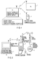
- FIG. 1 conceptually shows the basic arrangement of a radio communication system according to an embodiment of the present invention.
- a communication apparatus in which a communication channel and a control channel are exclusively assigned to a radio communication resource to be used.
- the apparatus includes a unit for executing data transmission/reception using the communication channel and a unit for executing a control procedure required for establishment of a radio link using the control channel.
- the information processing apparatus 1 is, for example, a notebook type personal computer (to be referred to as a PC hereinafter) that can be driven on a battery, and can communicate with a portable device such as a portable telephone 2 by establishing a local link thereto by radio. In a state where this radio link is established, a user can, for example, remotely control the PC 1 by using the portable telephone 2 and exchange data such as mail and personal information with the PC 1 and the portable telephone 2.
- a notebook type personal computer to be referred to as a PC hereinafter
- the PC 1 can be simultaneously connected to a plurality of remote terminals, e.g., the portable telephone 2 and another PC (multipoint). In this case, even while connection is being established, the PC 1 can enter a terminal search mode of searching for a new terminal and can also enter a connection establishment request wait mode, which dynamically allows a new terminal to join the network.
- a terminal search mode of searching for a new terminal can also enter a connection establishment request wait mode, which dynamically allows a new terminal to join the network.
- a search is made for a terminal that is preset in a range (communication zone) where radio waves can reach, and processing for the acquisition of information necessary for connection is performed.
- a terminal search message is broadcast.
- the terminal search wait mode the terminal search message transmitted from a remote terminal to search for a terminal is detected, and processing for transmitting a message responding to the detected message is performed.
- the connection establishment request wait mode the connection establishment request message transmitted from the remote terminal is detected, and processing for the establishment of connection in response to the detected message is performed.
- a message in a control procedure (terminal search, terminal search wait, and connection establishment request wait) required for new radio link establishment is exchanged by using a control channel. Since a radio communication resource is exclusively used between this control channel and a communication channel for data transmission/reception, if communication is being performed in making a terminal search or the like, the communication (communication mode) is temporarily stopped.
- This embodiment has a control information communication timing control section for dynamically controlling the timing at which a control procedure (terminal search, terminal search wait, and connection establishment request wait) necessary for the establishment of a new radio link is executed and the time interval of the control procedure in accordance with the traffic state of a communication channel, the current power supply state, and the like. With this control section, parameters associated with connection control can be optimized.
- the portable telephone 2 transmits/receives speech or data to/from base stations 3 for portable telephones, which are installed in various areas, by using radio waves in the 800-MHz band.
- the base station 3 encompasses a predetermined radio area, in which communication with the portable telephone 2 is implemented.
- a server 5 is connected to the base station 3 through a public switched telephone network 4.
- the user of the portable telephone 2 can also perform speech communication by using a headset 6.
- This portable telephone 2 has a radio communication interface for transmitting/receiving radio waves in the 2.45-GHz band to/from the PC 1, in addition to a radio communication interface for transmitting receiving radio waves in the 800-MHz band to/from the base station 3.
- the portable telephone 2 also has an LCD for displaying data, a key operation portion for inputting data, and the like.
- the PC 1 and portable telephone 2 are connected to each other through radio waves in a specific frequency band which are different from the radio waves used in the portable telephone system. More specifically, a 2.45-GHz band Bluetooth system is used.
- the Bluetooth system is a short-range radio communication standard, and implements radio communication within about 10 m by using radio waves in the 2.45-GHz band.
- the PC 1 includes an antenna portion for transmitting/receiving radio waves in the 2.45-GHz band to/from the portable telephone 2, an LCD used as a display monitor, a keyboard for inputting data, and the like.
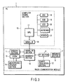
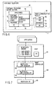
- FIG. 3 is a block diagram showing the hardware arrangement of the PC 1. The hardware portion required to implement this system will be mainly described below.
- the PC 1 incorporates.a radio communication module 7 for communicating with the portable telephone 2 by using radio waves in the 2.45-GHz band.
- the radio communication module 7 includes an antenna section 8, an RF (Radio Frequency) section 9, a baseband section 10, a memory section 11, a quartz oscillation section 12, an AD/DA conversion section 13, and a microphone/speaker section 14.
- RF Radio Frequency
- a similar radio communication module is also incorporated in the portable telephone 2.
- the radio communication module 7 is connected to a computer engine section 15 as a main unit of the personal computer through a serial interface 16 such as a USB.
- the antenna section 8 is a section that implements radio communication with the portable telephone 2 and transmits/receives radio waves in the 2.45-GHz band.
- the RF section 9 mixes the radio wave received through the antenna section 8 with a fundamental frequency signal oscillated by the quartz oscillation section 12 to convert the radio wave into an intermediate frequency signal, and then demodulates it into a digital signal that can be processed by the baseband section 10.
- the baseband section 10 performs protocol processing.
- the signal input through the antenna section 8 and RF section 9 is converted into a data string that can be processed by the CPU in the baseband section 10.
- the baseband section 10 converts transmission data into a signal that can be processed by the RF section 9 in accordance with a predetermined protocol, and the RF section 9 modulates the signal into a radio wave in the 2.45-GHz band, thereby transmitting it from the antenna section 8.
- the microphone/speaker section 14 is a device for inputting/outputting speech signals, and is connected to the baseband section 10 through the AD/DA conversion section 13.
- the computer engine section 15 has an MPU (computer engine) 17 including a CPU, memory, and peripheral control circuits, an LED (Light Emitting Diode) 18 for performing alarm display and the like, a USB interface 19 for connecting a peripheral device based on USB (Universal Serial Bus) standards, an LCD (Liquid Crystal Display) 20 used as a display monitor, a keyboard 21 for data input, PCMCIA (Personal Computer Memory Card International Association) interface 22 for mounting a PC card, and the like.
- MPU computer engine 17 including a CPU, memory, and peripheral control circuits, an LED (Light Emitting Diode) 18 for performing alarm display and the like, a USB interface 19 for connecting a peripheral device based on USB (Universal Serial Bus) standards, an LCD (Liquid Crystal Display) 20 used as a display monitor, a keyboard 21 for data input, PCMCIA (Personal Computer Memory Card International Association) interface 22 for mounting a PC card, and the like.
- MPU computer engine
- LCD Liquid Crystal Display
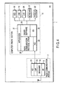
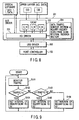
- FIG. 4 is a block diagram showing the software arrangement of the PC 1.
- FIG. 4 shows the structure of the PC 1 incorporating a radio communication protocol stack for 2.4-GHz band radio communication on the computer engine section 15 side.
- the RF section 9 and baseband section 10 which are hardware, are provided, and an LMP (Link Management Protocol) 23 for controlling a radio link with the radio communication apparatus on the portable telephone 2 side by radio waves and an HCI (Host Control Interface) 24 for performing serial interface processing for the computer engine section 15 are incorporated in the baseband section 10.
- LMP Link Management Protocol
- HCI Host Control Interface
- the computer engine section 15 incorporates a 2.45-GHz band radio communication protocol stack 28, an HCI 29 for performing serial interface processing on the radio communication module 7 side, and the like, in addition to an OS (Operating System) 25, drive software 26 for controlling various peripheral devices, and various applications 27 such as wordprocessor software, spreadsheet software, electronic mail software, and system software for implementing a remote control function, which are incorporated as standard software for the PC.
- OS Operating System
- applications 27 such as wordprocessor software, spreadsheet software, electronic mail software, and system software for implementing a remote control function, which are incorporated as standard software for the PC.
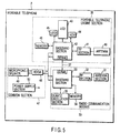
- FIG. 5 is a block diagram showing the hardware arrangement of the portable telephone 2. The hardware portion required to implement this system will be mainly described.
- radio communication module 30 for communicating with the PC 1 by using radio waves in the 2.45-GHz band, an antenna section 31, RF section 32, baseband section 33, memory section 34, and quartz oscillation section 35 are incorporated in the portable telephone 2.
- the radio communication module 30 and a portable telephone engine section 36 are connected to each other through a serial interface 37.
- the antenna section 31 is a section for transmitting/receiving radio waves in the 2.45-GHz band to implement radio communication with the PC 1.
- the RF section 32 mixes the radio wave received through the antenna section 31 with a fundamental frequency signal oscillated by the quartz oscillation section 35 to convert the radio wave into an intermediate frequency signal, and then demodulates it into a digital signal that can be processed by the baseband section 33.
- the baseband section 33 performs protocol processing. The signal input through the antenna section 31 and RF section 32 is converted into a data string that can be processed by the CPU in the baseband section 33.
- the baseband section 33 converts transmission data into a signal that can be processed by the RF section 32 in accordance with a predetermined protocol, and the RF section 32 modulates the signal into a radio wave in the 2.45-GHz band, thereby transmitting it from the antenna section 31.
- the portable telephone engine section 36 includes an LCD 43 for data display, a key operation section 44 for data input, an LED 45 for alarm display and the like, a memory 46 for data storage, and the like, in addition to an antenna 40 for a portable telephone, an RF section 41, and a baseband section 42.
- an AD/DA conversion section 48 As a common section 47, an AD/DA conversion section 48, microphone/speaker 49, and power supply section 50 are provided.
- FIG. 6 is a block diagram showing the software arrangement of the portable telephone 2.
- FIG. 6 shows the structure of the portable telephone 2 in which a radio communication protocol stack for 2.45-GHz band radio communication is mounted on the portable telephone engine section 36 side.
- the RF section 32 and baseband section 33 which are hardware, are arranged on the radio communication module 30 side of the portable telephone 2.
- An LMP (Link Management Protocol) 51 for controlling a radio link to the radio communication apparatus on the PC 1 side by radio waves and an HCI (Host Control Interface) 52 for performing serial interface processing for the portable telephone engine section 36 are mounted in the baseband section 33.
- the portable telephone engine section 36 incorporates an application 54 including system software and the like for implementing a remote control function, a radio communication protocol stack 55 for 2.45-GHz radio communication, and an HCI 56 for performing serial interface processing for the radio communication module 30 side.
- Parameter optimization processing which is a feature of this embodiment will be described by exemplifying the case wherein the Bluetooth technique as a 2.45-GHz band radio communication standard is used. Bluetooth specifications will be briefly described first.
- the Bluetooth system uses a frequency hopping technique of performing packet transmission of data by TDD (Time Division Duplex) with one slot corresponding to 625 ⁇ s and a change in frequency in units of packets.
- TDD Time Division Duplex
- a radio network called a piconet is formed between one master and a maximum of seven slaves to perform communication.
- Data channels communication channels
- ACL asynchronous data channel
- SCO synchronous speech channel
- connection establishment request processing A given terminal that permits another terminal to search out (find) the given terminal itself performs Inquiry Scan (terminal search wait processing) to respond to an Inquiry message.
- Inquiry Scan terminal search wait processing
- Page Scan connection establishment request wait processing
- FIG. 7 shows the arrangement of the PC 1 incorporating the Bluetooth system.
- An OS, Bluetooth bus driver, and application are resident on the memory of the PC 1 (host side), and the Bluetooth device itself (host controller side) is connected as, for example, a USB device.
- a host 101 and host controller 102 communicate with each other in accordance with an HCI (Host Controller Interface).
- the host controller 102 includes a link manager 103 and link controller 104.
- the operation of an RF circuit 105 is controlled by the link manager 103 and link controller 104.
- the host 101 transmits an HCI command to the host controller 102.
- An Inquiry command may be singly transmitted every time an application is to perform communication, or Inquiry may be periodically performed.
- two parameters, Max_Period_Length and Min_Period_Length, used to determine the time intervals of Inquiry in an HCI command are set.
- the host controller 102 determines an arbitrary value in the range between the designated maximum value of Max_Period_Length and the designated minimum value of Min_Period_Length. Inquiry is performed every time interval corresponding to the determined value.
- Max_Period_Length is defined to have a range of 3.84 sec to 83884.8 sec.
- Min_Period_Length is defined to have a range of 2.56 sec to 83883.52 sec.
- InquiryScan_Interval/Pagescan_Interval for designating the time interval of Inquiry Scan/Page Scan must be set.
- InquiryScan_Interval/PageScan_Interval has a range of 11.25 ms to 2560 ms and a default value of 1.28 sec.
- the link controller 104 has two major states, namely a standby state and connection state.
- the connection state includes four modes, namely an active mode, sniff mode, hold mode, and park mode.
- the sniff mode, hold mode, and park mode are power saving modes. If ACL connections are present in performing Inquiry, Inquiry Scan, or Page Scan, these ACL connections must be temporarily shifted to the park mode or hold mode, which is a power saving mode of a connection state to ensure an available slot for Inquiry, Inquiry Scan, or Page Scan. That is, data communication is temporarily stopped.
- a feature of this embodiment is that such time intervals are optimized in accordance with the state of a device and the state of connection.
- the bus driver converts data from an upper protocol driver into Bluetooth data and controls a Bluetooth link.
- FIG. 8 shows the arrangement of drivers and the flow of ACL/SCO data.
- An upper layer which is an upper protocol driver of a bus driver 201 establishes ACL connection for each CID (logical channel ID).
- an L2CAP (Logical Link Control and Adaptation Protocol) 202 establishes connection for each Connection_Handle (CH) which is a physical channel identifier.
- An HCI driver 203 communicates HCI data packets to a USB driver 205, which serves to control the host controller 102, by using one transmission port and one reception port.
- the bus driver 201 can therefore have communication traffic information, e.g., information indicating how many active ACL and SCO connections are currently established, a specific packet type used by each connection, and a specific speed of data transmission request from the upper layer. Since the HCI driver 203 can systematically monitor traffics, control can be performed in accordance with the traffic state of a current communication channel by using a data traffic monitor section & Inquiry/Inquiry Scan/Page Scan interval decision section 204.
- communication traffic information e.g., information indicating how many active ACL and SCO connections are currently established, a specific packet type used by each connection, and a specific speed of data transmission request from the upper layer. Since the HCI driver 203 can systematically monitor traffics, control can be performed in accordance with the traffic state of a current communication channel by using a data traffic monitor section & Inquiry/Inquiry Scan/Page Scan interval decision section 204.
- the time interval of Inquiry Scan is set to be long, and Inquiry is not performed unless an application requests connection establishment.
- the time intervals of Inquiry Scan and Page Scan are minimized to allow Inquiry Scan and Page Scan to be performed most frequently or Inquiry is periodically performed to acquire information about terminals within the communication zone in advance.
- the flow chart of FIG. 9 shows an example of Inquiry Scan Optimization Control Processing.
- a data traffic is monitored (step S101). It is then checked whether the current traffic amount exceeds a predetermined threshold a , falls within the range of the threshold a to a threshold b (b ⁇ a), or is equal to or less than the threshold b (steps S102 and S103). If the traffic amount exceeds the threshold a (YES in step S102), the time interval of Inquiry Scan is set to a maximum value X1 to prevent communication performance from deteriorating due to Inquiry Scan (step S104). Likewise, if the traffic amount falls within the range of the threshold a to the threshold b (YES in step S103), the time interval of Inquiry Scan is set to an intermediate value X2 (step S105). If the traffic amount is equal to or less than the threshold b (NO in step S103), the time interval of Inquiry Scan is set to a minimum value X3 (step S106). In this case, X1 > X2 > X3.
- the flow chart of FIG. 10 shows an example of Inquiry optimization control processing.
- a data traffic is monitored (step S101). It is then checked whether the current traffic amount exceeds the predetermined threshold a , falls within the range of the threshold a to the threshold b (b ⁇ a), or is equal to or less than the threshold b (steps S102 and S103). If the traffic amount exceeds the threshold a (YES in step S102), the current mode is changed to a mode of stopping periodical transmission of Inquiry and issuing Inquiry only when an application or user requests the establishment of a new radio link in order to prevent communication performance from deteriorating due to Inquiry (step S107).
- the time interval of Inquiry is set to a predetermined value Y1 to periodically execute Inquiry (step S108). If the traffic amount is equal to or less than the threshold b (NO in step S103), the time interval of Inquiry is set to a minimum value Y2 (step S109). In this case, Y1 > Y2.
- the control in FIG. 9 or 10 can be applied to Page Scan as well.
- various traffic states e.g., whether current communication demands high communication performance and influences of a halt on current communication, are detected as well as the communication traffic amount, and appropriate control is executed in accordance with the detected states.
- optimization control is performed on the basis of a traffic state.
- the performance improves when control is performed in accordance with a user's use pattern. Assume that communication between PCs 1 or between the PC 1 and a PDA is to be started. In this case, if the user manually stops transmission by an application and performs Inquiry Scan and Page Scan instead of automatic execution of Inquiry Scan and Page Scan, a waste of the resource can be prevented. That is, the user or application can explicitly output an Inquiry Scan or Page Scan execution instruction. A specific example how such control becomes effective will be described.
- FIG. 11 shows a user interface window for an ad hoc network application.
- a member join button is prepared on this window. Assume that a given terminal is to join the network. In this case, the user presses this member join button on an application on a terminal serving as a master in a piconet of the network. At the same time, the application temporarily stops data transmission at a proper timing to allow execution of Inquiry Scan/Pate Scan, or informs the lower bus driver 201 of the presence of a terminal that has established connection. As indicted by the flow in FIG. 7, the instruction is transmitted to the host controller 102, and the bus driver 201 transmits the HCI command to the host controller 102, thus instructing periodical execution of Inquiry Scan/Page Scan.
- the host controller 102 shifts them to the park mode or hold mode and starts Inquiry Scan/Page Scan to quickly establish connection.
- the host controller 102 then restores the ACL connections, which have been shifted to the power saving mode, to the active state to resume data communication.
- a terminal serving as a master is preferably made to preferentially execute either radio link establishment processing or data communication processing in accordance with a user operation by using a user interface window like the one shown in FIG. 12. If “data communication stop” or “terminal search priority” in FIG. 12 is selected, radio link establishment processing is preferentially performed. If “data communication priority” or “no terminal search” is selected, data communication processing is preferentially performed. A detailed control procedure will be described below with reference to the flow chart of FIG. 13.
- the mode selected by the user is "data communication stop", “terminal search priority”, “data communication priority”, or “no terminal search” (steps S111 to S113). If “data communication stop” is selected (YES in step S111), the currently active link is set in the hold or park mode to temporarily stop communication (step S114). The time interval of Inquiry Scan is then set to the minimum value to quickly respond to a terminal search message (step S115). If "terminal search priority" is selected (YES in step S112), the time interval of Inquiry Scan is set to X2 (X2 > minimum value) to relatively quickly respond to a terminal search message (step S116).
- step S113 If “data communication priority” is selected (YES in step S113), the time interval of Inquiry Scan is set to the relatively large value X1 (X1 > X2) to minimize the chance of interruption of data communication under execution (step S117). If "no terminal search” is selected (NO in step S113), the time interval of Inquiry Scan is set to the maximum value to exclusively use the radio communication resource for data communication (step S118).
- the time interval of Inquiry is variably controlled in accordance with the mode selected by the user.
- the time interval of Page Scan is also variably controlled by the same procedure as described above.
- the third example of the optimization control processing of this embodiment will be described next.
- it is discriminated whether the PC 1 is driven on an external AC power supply or built-in battery. If the PC 1 is driven by the battery, the time interval of Inquiry Scan/Page Scan is set to be long, or Inquiry is issued only when a link request is received, thereby performing control for power saving.
- control is also performed to prolong the time interval as the battery residual capacity decreases.
- FIG. 14 shows the power supply management software of this embodiment.
- Information associated with a battery e.g., the residual capacity of the battery and information indicating whether the PC 1 is driven by the battery or external AC power supply, is managed in a system management memory (SMRAM) 304 under the control of a power supply management driver 302.
- SMRAM system management memory
- An OS 303 and HCI driver 301 in the bus driver 201 have interfaces with the power supply management driver 302, and can check the current power supply state through the power supply management driver 302.
- InquiryScan_Interval/PageScan_Interval can be set in increments of 0.625 ms according to the specifications.
- the time interval of Inquiry Scan/Page Scan is calculated by 0.625 X N.
- the default value of N is 2048, and the range of N is 18 ⁇ N ⁇ 4096.
- InquiryScan_Interval 0.625 ⁇ 2048 ⁇ 1 / C If, however, C ⁇ 0.5,
- the HCI driver transmits the HCI command to the host controller 102.
- Either the HCI driver 301 in FIG. 15 or the power supply management driver 302 can have a calculation means.
- information indicating that the battery driving mode and external power supply driving mode are switched is preferably registered in the OS 303 to allows acquisition of the information as an event.
- the OS 303 preferably informs the bus driver 201 of the information indicating the switching of the modes.
- an application program 401 for performing Bluetooth power supply control may be prepared as shown in FIG. 15, and the application program 401 may inquire the OS 303 about external power supply driving/battery driving and battery residual capacity in accordance with a request from the HCI driver 301 of the bus driver 201.
- step S201 whether the current operating power supply is the battery or external AC power supply is determined by checking whether the external AC power supply is connected. If the external AC power supply is connected and the PC 1 is driven by the external AC power supply, the default value is used as the time interval of Inquiry Scan.
- step S201 If no external AC power supply is connected and the PC 1 is driven by the battery (YES in step S201), the current battery residual capacity is checked (step S202).
- the time interval of Inquiry Scan is calculated from the battery residual capacity such that the time interval of Inquiry Scan prolongs with a decrease in battery residual capacity, and the time interval of Inquiry Scan is set to the calculated value (steps S203 and 5204).
- Inquiry may be set to a mode of stopping periodical transmission when the battery residual capacity decreases below a predetermined value, and performing transmission only when a link request is received.
- the mode of performing transmission only when such a request is received can be applied to Inquiry Scan/Page Scan.
- parameters for connection control can be optimized by dynamically controlling the execution timings and time intervals of Inquiry, Inquiry Scan, and Page Scan in accordance with a traffic state, user settings, and power supply state. This eliminates a waste of power and implements both an improvement in communication performance and connectability.
- parameter optimization control has been described above with particular emphasis on the PC 1.
- similar control can be applied to the portable telephone 2.
- the present invention can be applied to various electronic devices as long as they have communication apparatuses in which the radio communication resource is exclusively used between a communication channel and a control channel, and connection control is performed by inserting the control channel in the communication channel.
- control operations based on a traffic state, power supply state, and user settings have been separately described. However, a combination of these control operations can also be used. If, for example, the traffic is large, the time interval of connection control may be prolonged even in the AC power supply driving mode. In contrast to this, if the traffic is small, the time interval of connection control may be shortened even in the battery driving mode. In this manner, the time interval of connection control can be variously set in accordance with user settings.
- parameters associated with connection control e.g., the time interval of a terminal search and the time interval of terminal search wait processing, can be dynamically optimized, and hence an improvement in communication performance and suppression of power consumption can be realized.
Landscapes
- Engineering & Computer Science (AREA)
- Computer Networks & Wireless Communication (AREA)
- Signal Processing (AREA)
- Mobile Radio Communication Systems (AREA)
Claims (4)
- Kommunikationsvorrichtung, die ausgestaltet ist, um durch eine Batterie angetrieben zu werden und um mit einer Mehrzahl von Fern-Terminals verbunden zu sein, wobei die Vorrichtung umfasst:ein Mittel (7) zum periodischen Ausführen einer Abfrageabtastung;ein Mittel (302) zum Erfassen einer Restkapazität der Batterie; undein Mittel (204) zum dynamischen Steuern des Ausführungstimings der Anfrageabtastung basierend auf einem Bestimmungsergebnis des Erfassungsmittels (302);wobei das Mittel (204) zum dynamischen Steuern angepasst ist, um ein Zeitintervall der Abfrageabtastung mit der Abnahme der Restkapazität der Batterie zu verlängern;dadurch gekennzeichnet, dassdie Vorrichtung ferner ein Mittel (302) umfasst, um zu bestimmen, ob eine aktuelle arbeitende Leistungsversorgung die Batterie oder eine externe Leistungsversorgung ist; undwobei das Mittel (204) zum dynamischen Steuerns des Ausführungstimings der Abfrageabtastung angepasst ist, um das Ausführungstiming zusätzlich basierend auf einem Erfassungsergebnis des Erfassungsmittels (302) zu steuern; undwenn die aktuelle arbeitende Leistungsversorgung die externe Leistungsversorgung ist, das Zeitintervall auf einen Defaultwert gesetzt wird.
- Vorrichtung gemäß Anspruch 1, dadurch gekennzeichnet, dass die Abfrageabtastung ein Übertragen einer Terminalsuch-, einer Terminalsuchwarte- oder einer Verbindungsaufbauanforderungswarte-Nachricht und Antworten darauf umfasst.
- Steuerverfahren für eine Kommunikationsvorrichtung, die imstande ist, durch eine Batterie angetrieben zu werden und mit einer Mehrzahl von trennbaren Terminals verbunden werden kann, wobei das Verfahren folgende Schritte umfasst:periodisches Ausführen einer Abfrageabtastung;Bestimmen, ob die aktuelle arbeitende Leistungsversorgung die Batterie oder eine externe Leistungsversorgung (S201) ist;Erfassen einer Restkapazität der Batterie (S202); undDynamisches Steuern des Ausführungstimings der Abfrageabtastung basierend auf einem Bestimmungsergebnis des Bestimmungsschritts und eines Erfassungsergebnis des Erfassungsschritts (S203 bis S204),wobei ein Zeitintervall der Abfrageabtastung mit der Abnahme der Restkapazität der Batterie verlängert wird, wenn die aktuelle arbeitende Leistungsversorgung die Batterie ist, und das Zeitintervall auf einen Defaultwert gesetzt wird, wenn die aktuelle arbeitende Leistungsversorgung die externe Leistungsversorgung ist.
- Verfahren gemäß Anspruch 3, bei dem die Abfrageabtastung ein Übertragen einer Anschlusssuch-, einer Anschlusssuchwarte- oder einer Verbindungseinrichtungsanforderungswarte-Nachricht und Antworten darauf umfasst.
Applications Claiming Priority (2)
| Application Number | Priority Date | Filing Date | Title |
|---|---|---|---|
| JP37307399A JP4116212B2 (ja) | 1999-12-28 | 1999-12-28 | 通信装置およびその制御方法 |
| JP37307399 | 1999-12-28 |
Publications (3)
| Publication Number | Publication Date |
|---|---|
| EP1113690A2 EP1113690A2 (de) | 2001-07-04 |
| EP1113690A3 EP1113690A3 (de) | 2002-09-11 |
| EP1113690B1 true EP1113690B1 (de) | 2006-03-29 |
Family
ID=18501536
Family Applications (1)
| Application Number | Title | Priority Date | Filing Date |
|---|---|---|---|
| EP00128628A Expired - Lifetime EP1113690B1 (de) | 1999-12-28 | 2000-12-28 | Kommunikationseinrichtung und übereinstimmendes Steuerungsverfahren |
Country Status (4)
| Country | Link |
|---|---|
| US (1) | US7020467B2 (de) |
| EP (1) | EP1113690B1 (de) |
| JP (1) | JP4116212B2 (de) |
| DE (1) | DE60026921T2 (de) |
Families Citing this family (96)
| Publication number | Priority date | Publication date | Assignee | Title |
|---|---|---|---|---|
| EP1113684A1 (de) * | 1999-12-29 | 2001-07-04 | Koninklijke Philips Electronics N.V. | System, Endgerät und Verfahren zur gleichzeitigen Verbindung zu zwei TDMA-Übertragungssystemen |
| JP3566218B2 (ja) * | 2001-02-19 | 2004-09-15 | 株式会社東芝 | Bluetoothネットワーク通信方法およびシステム |
| JP3684163B2 (ja) * | 2001-03-07 | 2005-08-17 | 株式会社東芝 | Bluetoothネットワーク通信方法およびBluetoothネットワークで使用されるBluetooth機器 |
| FI113145B (fi) * | 2001-05-03 | 2004-02-27 | Nokia Corp | Laitteen piilottaminen |
| US7792484B2 (en) * | 2001-07-05 | 2010-09-07 | Telefonaktiebolaget Lm Ericsson (Publ) | Arrangement and a method in a telephony system permitting communication using a stationary telephony terminal via a mobile radio telephone |
| US7215923B2 (en) * | 2001-08-06 | 2007-05-08 | Broadcom Corporation | System and method for establishing a connection between wireless devices |
| US6742052B2 (en) * | 2001-08-09 | 2004-05-25 | International Business Machines Corporation | Wireless system bus |
| US6968219B2 (en) | 2001-08-15 | 2005-11-22 | Qualcomm, Incorporated | Method for reducing power consumption in bluetooth and CDMA modes of operation |
| CN100380825C (zh) * | 2001-08-15 | 2008-04-09 | 高通股份有限公司 | 双模式蓝牙/无线设备以及同步该设备的方法 |
| JP3837312B2 (ja) * | 2001-09-18 | 2006-10-25 | インターナショナル・ビジネス・マシーンズ・コーポレーション | コンピュータ装置、無線通信モジュール、無線通信モジュールの制御方法、プログラム |
| US7280518B2 (en) * | 2001-10-03 | 2007-10-09 | Freescale Semiconductor, Inc. | Method of operating a media access controller |
| JP3481926B2 (ja) | 2001-10-30 | 2003-12-22 | 株式会社東芝 | 無線通信装置および制御パラメータ設定方法 |
| US20030087658A1 (en) * | 2001-11-08 | 2003-05-08 | Jane Dashevsky | Partitioning responsibility between link manager and host controller interface firmware modules in wireless systems |
| TW540764U (en) * | 2001-12-04 | 2003-07-01 | Asustek Comp Inc | Multi-mode blue-tooth externally connected device |
| EP1324550B1 (de) * | 2001-12-28 | 2005-08-24 | Kabushiki Kaisha Toshiba | Tragbares Endgerät mit kombinierter Kommunikation über Funk mit geringer Reichweite für Direktverbindungen und zellularen Mobilfunk |
| JP4386732B2 (ja) | 2002-01-08 | 2009-12-16 | セブン ネットワークス, インコーポレイテッド | モバイルネットワークの接続アーキテクチャ |
| JP3705215B2 (ja) * | 2002-01-28 | 2005-10-12 | 日産自動車株式会社 | 移動体用情報提示装置 |
| JP2003229802A (ja) * | 2002-01-31 | 2003-08-15 | Alps Electric Co Ltd | 短距離無線伝送装置 |
| JP2003299146A (ja) * | 2002-02-01 | 2003-10-17 | Canon Inc | 無線通信装置 |
| FR2841669B1 (fr) * | 2002-06-27 | 2006-01-06 | St Microelectronics Sa | Procede de transmission de paquets de donnees entre deux unites esclaves et une unite maitre comprenant deux processeurs |
| US20040038645A1 (en) * | 2002-08-20 | 2004-02-26 | Jukka Rcunamaki | Carrier sensing multiple access with collision avoidance (CSMA/CA) scheme optimized for a priori known carrier usage for low duty cycle systems |
| JP4243801B2 (ja) * | 2002-10-10 | 2009-03-25 | パナソニック株式会社 | 通信リンクの確立を行う無線通信端末、その方法、その方法を実行するためのプログラム及び記録媒体 |
| JP4530610B2 (ja) * | 2002-11-26 | 2010-08-25 | パナソニック株式会社 | 無線通信装置 |
| JP2004180244A (ja) * | 2002-11-29 | 2004-06-24 | Alps Electric Co Ltd | 回線接続復旧方法および回線接続復旧プログラム |
| US7142814B2 (en) * | 2002-12-11 | 2006-11-28 | Shary Nassimi | Automatic Bluetooth inquiry mode headset |
| US6823401B2 (en) * | 2003-01-15 | 2004-11-23 | Hewlett-Packard Development Company, L.P. | Monitor for obtaining device state by intelligent sampling |
| JP3944089B2 (ja) * | 2003-01-31 | 2007-07-11 | 株式会社東芝 | 認証処理システム、端末認証装置、認証処理方法及び認証処理プログラム |
| JP2004247908A (ja) * | 2003-02-13 | 2004-09-02 | Tech Res & Dev Inst Of Japan Def Agency | 周波数ホッピング通信システム |
| WO2004109966A2 (en) * | 2003-06-05 | 2004-12-16 | Millennial Net | Protocol for configuring a wireless network |
| JP4055750B2 (ja) * | 2003-07-23 | 2008-03-05 | 松下電器産業株式会社 | 通信システムおよびそれに用いられる基地局および移動局 |
| JP4226599B2 (ja) * | 2003-08-08 | 2009-02-18 | 三菱電機株式会社 | 通信端末及び通信システム |
| JP3863871B2 (ja) * | 2003-09-09 | 2006-12-27 | 株式会社国際電気通信基礎技術研究所 | 送信レート制御方法および通信装置 |
| US8385985B2 (en) | 2003-11-25 | 2013-02-26 | Qualcomm Incorporated | Method for reducing power consumption in a multi-mode device |
| JP2005217548A (ja) | 2004-01-27 | 2005-08-11 | Nec Corp | 無線通信方法、無線通信システム、及び無線端末 |
| JP4073411B2 (ja) * | 2004-03-11 | 2008-04-09 | シャープ株式会社 | 通信機器及び該通信機器の低消費電力モード選択方法 |
| JP2005295310A (ja) * | 2004-04-01 | 2005-10-20 | Fuji Electric Holdings Co Ltd | 無線通信方法、無線通信システム、無線端末、プログラム、記録媒体 |
| JP4019088B2 (ja) * | 2004-04-28 | 2007-12-05 | 三星電子株式会社 | 無線網の予約スロットにおける状態決定方法及びシステム |
| US9246698B2 (en) * | 2004-05-07 | 2016-01-26 | Nokia Technologies Oy | Apparatus, and associated method, for facilitating a radio resource measurement in a radio communication system |
| US7526303B2 (en) * | 2004-05-19 | 2009-04-28 | Intel Corporation | Method and apparatus to manage power in a communication system |
| WO2006080084A1 (ja) * | 2005-01-28 | 2006-08-03 | Fujitsu Limited | 移動機 |
| US7848704B2 (en) * | 2005-03-04 | 2010-12-07 | Broadcom Corporation | Location system for bluetooth enabled devices |
| JP4561986B2 (ja) * | 2005-03-14 | 2010-10-13 | サクサ株式会社 | 無線端末機 |
| JP4561985B2 (ja) * | 2005-03-14 | 2010-10-13 | サクサ株式会社 | 無線端末機 |
| US9402272B2 (en) * | 2005-03-17 | 2016-07-26 | Core Wireless Licensing S.A.R.L. | Electronic device having a cellular communication mode and a radio communication mode |
| US7525932B2 (en) * | 2005-03-21 | 2009-04-28 | At&T Intellectual Property, I,L.P. | Methods, systems, and computer program products for implementing a virtual posting service |
| US8856311B2 (en) | 2005-06-30 | 2014-10-07 | Nokia Corporation | System coordinated WLAN scanning |
| US20070047506A1 (en) * | 2005-08-31 | 2007-03-01 | Froehling Timothy P | Methods and devices for dynamically adjusting page scan intervals of bluetooth enabled devices |
| JP4832848B2 (ja) * | 2005-10-13 | 2011-12-07 | パナソニック株式会社 | 無線アクセスポイント選択方法、無線装置、無線端末ならびにコンピュータプログラム |
| JP4779691B2 (ja) * | 2006-02-15 | 2011-09-28 | ミツミ電機株式会社 | チャンネルサーチ方法、及び、それを用いた通信装置 |
| JP4802028B2 (ja) | 2006-03-31 | 2011-10-26 | ミツミ電機株式会社 | 通信チャンネル設定方法、及び、それを用いた通信システム、並びに、通信装置 |
| CN101449525B (zh) * | 2006-04-29 | 2016-08-10 | 皇家飞利浦电子股份有限公司 | 控制传感器网络节点能量消耗的方法及装置 |
| US20080127223A1 (en) * | 2006-06-27 | 2008-05-29 | Christian Zechlin | System and method for communications operations |
| JP2008067183A (ja) * | 2006-09-08 | 2008-03-21 | Toshiba Corp | 無線通信端末 |
| EP2074490B1 (de) * | 2006-10-13 | 2020-08-12 | Nokia Technologies Oy | Verfahren, vorrichtung oder computerprogramm zum wechseln von zeitgeplanten zu nichtzeitgeplanten kommunikationsbetriebsarten |
| CN105338648A (zh) * | 2006-10-13 | 2016-02-17 | 诺基亚公司 | 用于从已调度通信模式改变到未调度通信模式的方法和设备 |
| EP1921875B1 (de) | 2006-10-23 | 2011-11-23 | Research In Motion Limited | System und Verfahren zum Abfragen einer Netzwerkkennung |
| US20080095130A1 (en) * | 2006-10-23 | 2008-04-24 | Ajay Puri | System and method of network identifier polling |
| US20080159210A1 (en) * | 2007-01-03 | 2008-07-03 | Texas Instruments, Inc. | System and method for automatic channel selection |
| US8811349B2 (en) * | 2007-02-21 | 2014-08-19 | Qualcomm Incorporated | Wireless node search procedure |
| JP4238918B2 (ja) * | 2007-04-02 | 2009-03-18 | 沖電気工業株式会社 | 通信制御装置、通信制御方法、通信制御プログラム、ノード及び通信システム |
| KR100881223B1 (ko) | 2007-05-28 | 2009-02-05 | (주)케이티에프테크놀로지스 | 질의 스캔 주기를 동적으로 조정할 수 있는 블루투스 장치및 방법, 그리고 이를 구현하기 위한 프로그램을 기록한기록매체 |
| JP5010985B2 (ja) * | 2007-05-30 | 2012-08-29 | 株式会社日立製作所 | センサノード |
| JP5056204B2 (ja) * | 2007-06-28 | 2012-10-24 | 富士電機株式会社 | 無線通信ネットワークシステム、無線端末、無線通信方法、無線通信プログラム |
| US8102796B2 (en) * | 2008-05-21 | 2012-01-24 | Wristop Technologies Oy | Wireless data communication method and wireless data communication system |
| JP4405569B1 (ja) * | 2008-07-23 | 2010-01-27 | 株式会社東芝 | 電子機器および通信制御方法 |
| US8620312B2 (en) * | 2010-01-05 | 2013-12-31 | Qualcomm Incorporated | Combined background and 20/40 coexistence scan |
| US8855627B2 (en) | 2010-06-14 | 2014-10-07 | Future Dial, Inc. | System and method for enhanced diagnostics on mobile communication devices |
| US9042243B2 (en) * | 2011-01-19 | 2015-05-26 | Qualcomm Incorporated | Adaptive peer discovery based on non peer discovery transmissions and device density for Wi-Fi |
| US8374652B2 (en) * | 2011-02-18 | 2013-02-12 | Texas Instruments Incorporated | Method and system for early termination of receive correlation window for bluetooth communication |
| US20120238205A1 (en) * | 2011-03-16 | 2012-09-20 | Nokia Corporation | method, apparatus and a computer program for out-of-band short-range communication carrier transport switching |
| JP2013030871A (ja) * | 2011-07-27 | 2013-02-07 | Hitachi Ltd | 無線通信システムおよび無線中継局 |
| US8996916B2 (en) * | 2011-08-16 | 2015-03-31 | Future Dial, Inc. | System and method for identifying problems via a monitoring application that repetitively records multiple separate consecutive files listing launched or installed applications |
| US9998945B2 (en) * | 2011-11-30 | 2018-06-12 | Shailesh Patil | Methods and apparatus to change peer discovery transmission frequency based on congestion in peer-to-peer networks |
| EP2611236B1 (de) * | 2011-12-29 | 2016-03-09 | BlackBerry Limited | Verfahren und Vorrichtung zum Empfang von Meldungen unter einer ersten und zweiten Netzwerkabdeckung |
| US8548510B2 (en) | 2011-12-29 | 2013-10-01 | Blackberry Limited | Method and apparatus for receiving messages under first and second network coverage |
| US10117092B2 (en) | 2012-08-16 | 2018-10-30 | Future Dial, Inc. | Mobile device transfer station |
| US10198366B2 (en) | 2012-08-16 | 2019-02-05 | Future Dial, Inc. | System for mobile computing device data synchronization |
| JP5651662B2 (ja) * | 2012-09-12 | 2015-01-14 | 株式会社東芝 | 無線通信装置 |
| US9814073B2 (en) * | 2013-01-30 | 2017-11-07 | Qualcomm Incorporated | PRACH-based proximity detection |
| JP6180786B2 (ja) * | 2013-05-17 | 2017-08-16 | 株式会社Nttドコモ | ユーザ装置、基地局、発見信号間隔調整方法、及びユーザ装置制御方法 |
| JP6269033B2 (ja) * | 2013-12-20 | 2018-01-31 | カシオ計算機株式会社 | 通信端末、通信制御方法及びプログラム |
| US10015808B2 (en) * | 2014-03-20 | 2018-07-03 | Panasonic Intellectual Property Corporation Of America | Method of detecting device resource-utilization and adjusting device behavior and related wireless device |
| JP6625887B2 (ja) | 2015-07-31 | 2019-12-25 | 任天堂株式会社 | 無線システム、無線機器、通信プログラム、および通信方法 |
| US10306451B2 (en) | 2015-07-31 | 2019-05-28 | Nintendo Co., Ltd. | Wireless system, wireless device, non-transitory computer-readable storage medium having stored therein communication program, and communication method |
| JP6703406B2 (ja) * | 2015-07-31 | 2020-06-03 | 任天堂株式会社 | 無線システム、無線機器、通信プログラム、および通信方法 |
| CN105204802B (zh) * | 2015-09-10 | 2019-05-21 | 海信集团有限公司 | 一种控制信息处理方法及装置 |
| JP6531593B2 (ja) | 2015-09-25 | 2019-06-19 | 富士通株式会社 | 通信方法、通信プログラムおよび情報処理装置 |
| US10165612B2 (en) * | 2016-06-16 | 2018-12-25 | I/O Interconnected, Ltd. | Wireless connecting method, computer, and non-transitory computer-readable storage medium |
| KR101856930B1 (ko) * | 2016-08-29 | 2018-05-11 | 현대자동차주식회사 | 유에스비 액세서리의 유에스비 통신 제어 방법 |
| WO2018145756A1 (en) * | 2017-02-10 | 2018-08-16 | Sonova Ag | Communication device having a dual protocol wireless interface |
| JP6842379B2 (ja) * | 2017-07-19 | 2021-03-17 | 株式会社Nttドコモ | ユーザ装置、及び間隔調整方法 |
| US10841976B2 (en) * | 2017-07-26 | 2020-11-17 | Advanced Bionics Ag | Communication device with wireless interface using different protocols |
| JP6613272B2 (ja) * | 2017-08-10 | 2019-11-27 | 株式会社野村総合研究所 | 情報処理装置、情報処理方法、及びプログラム |
| JP2018018530A (ja) * | 2017-08-29 | 2018-02-01 | カシオ計算機株式会社 | 通信装置、通信方法、及びプログラム |
| FR3074591A1 (fr) * | 2017-12-05 | 2019-06-07 | Orange | Procede de gestion des connexions d'un dispositif electronique. |
| KR20210031168A (ko) * | 2019-09-11 | 2021-03-19 | 삼성전자주식회사 | 블루투스 네트워크 환경에서 데이터 패킷을 수신하기 위한 전자 장치 및 그에 관한 방법 |
Family Cites Families (18)
| Publication number | Priority date | Publication date | Assignee | Title |
|---|---|---|---|---|
| JPH0714232B2 (ja) | 1988-07-01 | 1995-02-15 | 日本電信電話株式会社 | 報知周期切替方式 |
| EP0711089B1 (de) | 1989-03-03 | 2001-10-04 | Motorola, Inc. | Energiesparendes Protokoll für ein Kommunikationssystem |
| GB2241851A (en) * | 1990-03-09 | 1991-09-11 | Philips Electronic Associated | Optimising transmitter power in a communications system |
| JP2796464B2 (ja) * | 1991-12-27 | 1998-09-10 | 株式会社日立製作所 | 無線通信システム、および、無線通信方法 |
| US5382949A (en) * | 1993-02-01 | 1995-01-17 | Motorola, Inc. | Method for increasing battery life for selective call receivers |
| US5627882A (en) * | 1993-06-02 | 1997-05-06 | U.S. Philips Corporation | Enhanced power saving method for hand-held communications system and a hand-held communications system therefor |
| AU681721B2 (en) * | 1993-11-01 | 1997-09-04 | Alex K. Raith | Enhanced sleep mode in radiocommunication systems |
| JP2591467B2 (ja) * | 1994-04-18 | 1997-03-19 | 日本電気株式会社 | アクセス方式 |
| US6009325A (en) * | 1995-02-01 | 1999-12-28 | Motorola, Inc. | Method of and apparatus for operating a cellular phone in one of two modes |
| EP0899914A4 (de) * | 1996-10-30 | 2005-06-22 | Mitsubishi Electric Corp | Vorrichtung und verfahren zur steuerung von atm-verkehr |
| US5991635A (en) | 1996-12-18 | 1999-11-23 | Ericsson, Inc. | Reduced power sleep modes for mobile telephones |
| WO1998027766A2 (de) * | 1996-12-19 | 1998-06-25 | Siemens Aktiengesellschaft | Verfahren und vorrichtung zur reduktion des stromverbrauchs in mobilen multimode-kommunikationsendgeräten |
| US6438380B1 (en) * | 1997-02-28 | 2002-08-20 | Lucent Technologies Inc. | System for robust location of a mobile-transmitter |
| JP2988445B2 (ja) | 1997-07-25 | 1999-12-13 | 日本電気株式会社 | 移動無線システム |
| KR100234132B1 (ko) | 1997-07-26 | 1999-12-15 | 윤종용 | 이동통신단말기의 배터리 사용기간 연장방법 |
| US6044069A (en) | 1997-10-29 | 2000-03-28 | Conexant Systems, Inc. | Power management system for a mobile station |
| JP3114695B2 (ja) * | 1998-04-24 | 2000-12-04 | 日本電気株式会社 | 無線携帯情報端末及び無線データ送受信システム |
| JP3267569B2 (ja) * | 1998-11-27 | 2002-03-18 | 日本電気株式会社 | サーチャ制御方法とサーチャ制御装置及び無線通信装置 |
-
1999
- 1999-12-28 JP JP37307399A patent/JP4116212B2/ja not_active Expired - Lifetime
-
2000
- 2000-12-27 US US09/748,263 patent/US7020467B2/en not_active Expired - Lifetime
- 2000-12-28 DE DE60026921T patent/DE60026921T2/de not_active Expired - Fee Related
- 2000-12-28 EP EP00128628A patent/EP1113690B1/de not_active Expired - Lifetime
Also Published As
| Publication number | Publication date |
|---|---|
| EP1113690A2 (de) | 2001-07-04 |
| US7020467B2 (en) | 2006-03-28 |
| JP2001189689A (ja) | 2001-07-10 |
| DE60026921D1 (de) | 2006-05-18 |
| EP1113690A3 (de) | 2002-09-11 |
| JP4116212B2 (ja) | 2008-07-09 |
| US20010019956A1 (en) | 2001-09-06 |
| DE60026921T2 (de) | 2007-01-11 |
Similar Documents
| Publication | Publication Date | Title |
|---|---|---|
| EP1113690B1 (de) | Kommunikationseinrichtung und übereinstimmendes Steuerungsverfahren | |
| KR100472130B1 (ko) | 통신 장치 및 그 제어 방법 | |
| US7904023B2 (en) | Method for saving power in a wireless terminal and a terminal | |
| EP1392022B1 (de) | Leistungsverwaltungsverfahren und vorrichtung für ein wireless-lan-modul in einem computersystem | |
| US7660578B2 (en) | Method for saving power in a wireless terminal and a terminal | |
| EP2039190B1 (de) | Elektronisches gerät mit energieverwaltungssystem | |
| CN103119995B (zh) | 无线通信装置、无线通信方法以及处理电路 | |
| US20040176065A1 (en) | Low power operation in a personal area network communication system | |
| US7167721B2 (en) | Method of requesting an emergency rescue in a mobile communication terminal having a bluetooth device | |
| JP2001184149A (ja) | 情報処理装置および動作状態制御方法 | |
| WO2009030989A1 (en) | Bluetooth device with on-demand page scan | |
| US20120230319A1 (en) | Communication device, communication system, communication device control method, and communication device control program | |
| US8780775B2 (en) | Method and device for reducing power drain while camped on a wireless local area network | |
| KR101000967B1 (ko) | 무선 인터넷 접속 중계기 | |
| EP1542118B1 (de) | Hybrides mobiles Endgerät und dazugehöriges Steurungsverfahren | |
| US20040127216A1 (en) | Electronic apparatus, radio communication apparatus, and dispatch electronic control method | |
| KR100372867B1 (ko) | 블루투스 칩 내장 이동통신 단말기의 통신 전환 방법 및장치 | |
| JP2001159936A (ja) | コンピュータシステムおよびそのウェイクアップ方法 | |
| GB2384944A (en) | Reducing the power consumption of a Bluetooth device | |
| JP2010288120A (ja) | 通信装置、無線通信システム、通信方法および通信プログラム | |
| KR20030044673A (ko) | 휴대용 단말기의 절전 기능 전환 방법 | |
| KR19980084720A (ko) | 무선전화기에서 휴대장치의 소비전력 절약방법 |
Legal Events
| Date | Code | Title | Description |
|---|---|---|---|
| PUAI | Public reference made under article 153(3) epc to a published international application that has entered the european phase |
Free format text: ORIGINAL CODE: 0009012 |
|
| 17P | Request for examination filed |
Effective date: 20001228 |
|
| AK | Designated contracting states |
Kind code of ref document: A2 Designated state(s): AT BE CH CY DE DK ES FI FR GB GR IE IT LI LU MC NL PT SE TR |
|
| AX | Request for extension of the european patent |
Free format text: AL;LT;LV;MK;RO;SI |
|
| PUAL | Search report despatched |
Free format text: ORIGINAL CODE: 0009013 |
|
| AK | Designated contracting states |
Kind code of ref document: A3 Designated state(s): AT BE CH CY DE DK ES FI FR GB GR IE IT LI LU MC NL PT SE TR |
|
| AX | Request for extension of the european patent |
Free format text: AL;LT;LV;MK;RO;SI |
|
| 17Q | First examination report despatched |
Effective date: 20030115 |
|
| AKX | Designation fees paid |
Designated state(s): DE FR GB |
|
| GRAP | Despatch of communication of intention to grant a patent |
Free format text: ORIGINAL CODE: EPIDOSNIGR1 |
|
| GRAS | Grant fee paid |
Free format text: ORIGINAL CODE: EPIDOSNIGR3 |
|
| GRAA | (expected) grant |
Free format text: ORIGINAL CODE: 0009210 |
|
| AK | Designated contracting states |
Kind code of ref document: B1 Designated state(s): DE FR GB |
|
| REG | Reference to a national code |
Ref country code: GB Ref legal event code: FG4D |
|
| REF | Corresponds to: |
Ref document number: 60026921 Country of ref document: DE Date of ref document: 20060518 Kind code of ref document: P |
|
| ET | Fr: translation filed | ||
| PLBE | No opposition filed within time limit |
Free format text: ORIGINAL CODE: 0009261 |
|
| STAA | Information on the status of an ep patent application or granted ep patent |
Free format text: STATUS: NO OPPOSITION FILED WITHIN TIME LIMIT |
|
| 26N | No opposition filed |
Effective date: 20070102 |
|
| PGFP | Annual fee paid to national office [announced via postgrant information from national office to epo] |
Ref country code: FR Payment date: 20081212 Year of fee payment: 9 |
|
| PGFP | Annual fee paid to national office [announced via postgrant information from national office to epo] |
Ref country code: DE Payment date: 20081229 Year of fee payment: 9 |
|
| PGFP | Annual fee paid to national office [announced via postgrant information from national office to epo] |
Ref country code: GB Payment date: 20081224 Year of fee payment: 9 |
|
| GBPC | Gb: european patent ceased through non-payment of renewal fee |
Effective date: 20091228 |
|
| REG | Reference to a national code |
Ref country code: FR Ref legal event code: ST Effective date: 20100831 |
|
| PG25 | Lapsed in a contracting state [announced via postgrant information from national office to epo] |
Ref country code: FR Free format text: LAPSE BECAUSE OF NON-PAYMENT OF DUE FEES Effective date: 20091231 |
|
| PG25 | Lapsed in a contracting state [announced via postgrant information from national office to epo] |
Ref country code: DE Free format text: LAPSE BECAUSE OF NON-PAYMENT OF DUE FEES Effective date: 20100701 |
|
| PG25 | Lapsed in a contracting state [announced via postgrant information from national office to epo] |
Ref country code: GB Free format text: LAPSE BECAUSE OF NON-PAYMENT OF DUE FEES Effective date: 20091228 |