EP1113196A2 - Dispositif de commande hydraulique pour une transmission automatique - Google Patents
Dispositif de commande hydraulique pour une transmission automatique Download PDFInfo
- Publication number
- EP1113196A2 EP1113196A2 EP00128125A EP00128125A EP1113196A2 EP 1113196 A2 EP1113196 A2 EP 1113196A2 EP 00128125 A EP00128125 A EP 00128125A EP 00128125 A EP00128125 A EP 00128125A EP 1113196 A2 EP1113196 A2 EP 1113196A2
- Authority
- EP
- European Patent Office
- Prior art keywords
- valve
- pressure
- friction elements
- hydraulic
- hydraulic pressure
- Prior art date
- Legal status (The legal status is an assumption and is not a legal conclusion. Google has not performed a legal analysis and makes no representation as to the accuracy of the status listed.)
- Granted
Links
Images


Classifications
-
- F—MECHANICAL ENGINEERING; LIGHTING; HEATING; WEAPONS; BLASTING
- F16—ENGINEERING ELEMENTS AND UNITS; GENERAL MEASURES FOR PRODUCING AND MAINTAINING EFFECTIVE FUNCTIONING OF MACHINES OR INSTALLATIONS; THERMAL INSULATION IN GENERAL
- F16H—GEARING
- F16H61/00—Control functions within control units of change-speed- or reversing-gearings for conveying rotary motion ; Control of exclusively fluid gearing, friction gearing, gearings with endless flexible members or other particular types of gearing
- F16H61/02—Control functions within control units of change-speed- or reversing-gearings for conveying rotary motion ; Control of exclusively fluid gearing, friction gearing, gearings with endless flexible members or other particular types of gearing characterised by the signals used
- F16H61/0202—Control functions within control units of change-speed- or reversing-gearings for conveying rotary motion ; Control of exclusively fluid gearing, friction gearing, gearings with endless flexible members or other particular types of gearing characterised by the signals used the signals being electric
- F16H61/0204—Control functions within control units of change-speed- or reversing-gearings for conveying rotary motion ; Control of exclusively fluid gearing, friction gearing, gearings with endless flexible members or other particular types of gearing characterised by the signals used the signals being electric for gearshift control, e.g. control functions for performing shifting or generation of shift signal
- F16H61/0206—Layout of electro-hydraulic control circuits, e.g. arrangement of valves
-
- F—MECHANICAL ENGINEERING; LIGHTING; HEATING; WEAPONS; BLASTING
- F16—ENGINEERING ELEMENTS AND UNITS; GENERAL MEASURES FOR PRODUCING AND MAINTAINING EFFECTIVE FUNCTIONING OF MACHINES OR INSTALLATIONS; THERMAL INSULATION IN GENERAL
- F16H—GEARING
- F16H61/00—Control functions within control units of change-speed- or reversing-gearings for conveying rotary motion ; Control of exclusively fluid gearing, friction gearing, gearings with endless flexible members or other particular types of gearing
- F16H61/12—Detecting malfunction or potential malfunction, e.g. fail safe; Circumventing or fixing failures
-
- F—MECHANICAL ENGINEERING; LIGHTING; HEATING; WEAPONS; BLASTING
- F16—ENGINEERING ELEMENTS AND UNITS; GENERAL MEASURES FOR PRODUCING AND MAINTAINING EFFECTIVE FUNCTIONING OF MACHINES OR INSTALLATIONS; THERMAL INSULATION IN GENERAL
- F16H—GEARING
- F16H59/00—Control inputs to control units of change-speed-, or reversing-gearings for conveying rotary motion
- F16H2059/006—Overriding automatic control
-
- F—MECHANICAL ENGINEERING; LIGHTING; HEATING; WEAPONS; BLASTING
- F16—ENGINEERING ELEMENTS AND UNITS; GENERAL MEASURES FOR PRODUCING AND MAINTAINING EFFECTIVE FUNCTIONING OF MACHINES OR INSTALLATIONS; THERMAL INSULATION IN GENERAL
- F16H—GEARING
- F16H61/00—Control functions within control units of change-speed- or reversing-gearings for conveying rotary motion ; Control of exclusively fluid gearing, friction gearing, gearings with endless flexible members or other particular types of gearing
- F16H61/02—Control functions within control units of change-speed- or reversing-gearings for conveying rotary motion ; Control of exclusively fluid gearing, friction gearing, gearings with endless flexible members or other particular types of gearing characterised by the signals used
- F16H61/0262—Control functions within control units of change-speed- or reversing-gearings for conveying rotary motion ; Control of exclusively fluid gearing, friction gearing, gearings with endless flexible members or other particular types of gearing characterised by the signals used the signals being hydraulic
- F16H61/0276—Elements specially adapted for hydraulic control units, e.g. valves
- F16H2061/0288—Relay valve, e.g. valve arranged between shift valve and servo
-
- F—MECHANICAL ENGINEERING; LIGHTING; HEATING; WEAPONS; BLASTING
- F16—ENGINEERING ELEMENTS AND UNITS; GENERAL MEASURES FOR PRODUCING AND MAINTAINING EFFECTIVE FUNCTIONING OF MACHINES OR INSTALLATIONS; THERMAL INSULATION IN GENERAL
- F16H—GEARING
- F16H61/00—Control functions within control units of change-speed- or reversing-gearings for conveying rotary motion ; Control of exclusively fluid gearing, friction gearing, gearings with endless flexible members or other particular types of gearing
- F16H61/12—Detecting malfunction or potential malfunction, e.g. fail safe; Circumventing or fixing failures
- F16H2061/1204—Detecting malfunction or potential malfunction, e.g. fail safe; Circumventing or fixing failures for malfunction caused by simultaneous engagement of different ratios resulting in transmission lock state or tie-up condition
-
- F—MECHANICAL ENGINEERING; LIGHTING; HEATING; WEAPONS; BLASTING
- F16—ENGINEERING ELEMENTS AND UNITS; GENERAL MEASURES FOR PRODUCING AND MAINTAINING EFFECTIVE FUNCTIONING OF MACHINES OR INSTALLATIONS; THERMAL INSULATION IN GENERAL
- F16H—GEARING
- F16H61/00—Control functions within control units of change-speed- or reversing-gearings for conveying rotary motion ; Control of exclusively fluid gearing, friction gearing, gearings with endless flexible members or other particular types of gearing
- F16H61/12—Detecting malfunction or potential malfunction, e.g. fail safe; Circumventing or fixing failures
- F16H2061/1232—Bringing the control into a predefined state, e.g. giving priority to particular actuators or gear ratios
-
- F—MECHANICAL ENGINEERING; LIGHTING; HEATING; WEAPONS; BLASTING
- F16—ENGINEERING ELEMENTS AND UNITS; GENERAL MEASURES FOR PRODUCING AND MAINTAINING EFFECTIVE FUNCTIONING OF MACHINES OR INSTALLATIONS; THERMAL INSULATION IN GENERAL
- F16H—GEARING
- F16H61/00—Control functions within control units of change-speed- or reversing-gearings for conveying rotary motion ; Control of exclusively fluid gearing, friction gearing, gearings with endless flexible members or other particular types of gearing
- F16H61/12—Detecting malfunction or potential malfunction, e.g. fail safe; Circumventing or fixing failures
- F16H2061/124—Limiting the input power, torque or speed
-
- F—MECHANICAL ENGINEERING; LIGHTING; HEATING; WEAPONS; BLASTING
- F16—ENGINEERING ELEMENTS AND UNITS; GENERAL MEASURES FOR PRODUCING AND MAINTAINING EFFECTIVE FUNCTIONING OF MACHINES OR INSTALLATIONS; THERMAL INSULATION IN GENERAL
- F16H—GEARING
- F16H61/00—Control functions within control units of change-speed- or reversing-gearings for conveying rotary motion ; Control of exclusively fluid gearing, friction gearing, gearings with endless flexible members or other particular types of gearing
- F16H61/12—Detecting malfunction or potential malfunction, e.g. fail safe; Circumventing or fixing failures
- F16H2061/1244—Keeping the current state
-
- F—MECHANICAL ENGINEERING; LIGHTING; HEATING; WEAPONS; BLASTING
- F16—ENGINEERING ELEMENTS AND UNITS; GENERAL MEASURES FOR PRODUCING AND MAINTAINING EFFECTIVE FUNCTIONING OF MACHINES OR INSTALLATIONS; THERMAL INSULATION IN GENERAL
- F16H—GEARING
- F16H61/00—Control functions within control units of change-speed- or reversing-gearings for conveying rotary motion ; Control of exclusively fluid gearing, friction gearing, gearings with endless flexible members or other particular types of gearing
- F16H61/12—Detecting malfunction or potential malfunction, e.g. fail safe; Circumventing or fixing failures
- F16H2061/1256—Detecting malfunction or potential malfunction, e.g. fail safe; Circumventing or fixing failures characterised by the parts or units where malfunctioning was assumed or detected
- F16H2061/126—Detecting malfunction or potential malfunction, e.g. fail safe; Circumventing or fixing failures characterised by the parts or units where malfunctioning was assumed or detected the failing part is the controller
- F16H2061/1264—Hydraulic parts of the controller, e.g. a sticking valve or clogged channel
-
- F—MECHANICAL ENGINEERING; LIGHTING; HEATING; WEAPONS; BLASTING
- F16—ENGINEERING ELEMENTS AND UNITS; GENERAL MEASURES FOR PRODUCING AND MAINTAINING EFFECTIVE FUNCTIONING OF MACHINES OR INSTALLATIONS; THERMAL INSULATION IN GENERAL
- F16H—GEARING
- F16H61/00—Control functions within control units of change-speed- or reversing-gearings for conveying rotary motion ; Control of exclusively fluid gearing, friction gearing, gearings with endless flexible members or other particular types of gearing
- F16H61/12—Detecting malfunction or potential malfunction, e.g. fail safe; Circumventing or fixing failures
- F16H2061/1256—Detecting malfunction or potential malfunction, e.g. fail safe; Circumventing or fixing failures characterised by the parts or units where malfunctioning was assumed or detected
- F16H2061/126—Detecting malfunction or potential malfunction, e.g. fail safe; Circumventing or fixing failures characterised by the parts or units where malfunctioning was assumed or detected the failing part is the controller
- F16H2061/1268—Electric parts of the controller, e.g. a defect solenoid, wiring or microprocessor
-
- F—MECHANICAL ENGINEERING; LIGHTING; HEATING; WEAPONS; BLASTING
- F16—ENGINEERING ELEMENTS AND UNITS; GENERAL MEASURES FOR PRODUCING AND MAINTAINING EFFECTIVE FUNCTIONING OF MACHINES OR INSTALLATIONS; THERMAL INSULATION IN GENERAL
- F16H—GEARING
- F16H2306/00—Shifting
-
- F—MECHANICAL ENGINEERING; LIGHTING; HEATING; WEAPONS; BLASTING
- F16—ENGINEERING ELEMENTS AND UNITS; GENERAL MEASURES FOR PRODUCING AND MAINTAINING EFFECTIVE FUNCTIONING OF MACHINES OR INSTALLATIONS; THERMAL INSULATION IN GENERAL
- F16H—GEARING
- F16H61/00—Control functions within control units of change-speed- or reversing-gearings for conveying rotary motion ; Control of exclusively fluid gearing, friction gearing, gearings with endless flexible members or other particular types of gearing
- F16H61/68—Control functions within control units of change-speed- or reversing-gearings for conveying rotary motion ; Control of exclusively fluid gearing, friction gearing, gearings with endless flexible members or other particular types of gearing specially adapted for stepped gearings
- F16H61/684—Control functions within control units of change-speed- or reversing-gearings for conveying rotary motion ; Control of exclusively fluid gearing, friction gearing, gearings with endless flexible members or other particular types of gearing specially adapted for stepped gearings without interruption of drive
- F16H61/686—Control functions within control units of change-speed- or reversing-gearings for conveying rotary motion ; Control of exclusively fluid gearing, friction gearing, gearings with endless flexible members or other particular types of gearing specially adapted for stepped gearings without interruption of drive with orbital gears
Definitions
- the invention relates to an automatic transmission mounted in a vehicle, and more particularly to a hydraulic control apparatus for controlling friction elements in such a transmission.
- interlock valve (134, 136, 138 and 140 in Fig. 2 of the aforementioned disclosure) for providing hydraulic pressure to each friction element as a signal pressure during failures.
- the interlock valve is a valve used to cut off all hydraulic pressure to friction elements disengaged at preset speeds, and hence when a failure occurs at a preset speed, that speed is fixed. As a result, it is possible to resolve the problems of insufficient drive force or over-revving by maintaining a constant speed when failures occur.
- a hydraulic control apparatus for an automatic transmission of the type of hydraulic control apparatus provided with a plurality of friction elements and hydraulic servos for operating such, and wherein a plurality of speeds can be achieved by engaging at least two friction elements at a time out of the plurality of friction elements; and provided with a switching means for cutting off hydraulic control to the friction elements other than the friction elements engaged in order to achieve each speed within the plurality of speeds; wherein the plurality of speeds includes a third speed which, from among the friction elements, engages at least the first and third friction element (C-1, C-3) and disengages the second friction element (C-2), a fourth speed which engages the first and second friction element (C-1, C-2) and disengages the third friction element (C-3), and a fifth speed which engages the second and third friction elements (C-2, C-3) and disengages the first friction element (C-1); and said switching means includes a first switching valve (55) which cuts off hydraulic control to the first friction element
- the structure is effective as a second aspect for the structure to be further equipped with a plurality of control means (71-74) capable of adjusting the hydraulic pressure to each hydraulic servo (81-84) that operate the plurality of friction elements; wherein the hydraulic pressure from the plurality of control means is provided to each of the hydraulic servos.
- a third aspect is effective for the structure to be provided with a hydraulic pressure source and first and second oil paths (L31, L11) connecting the hydraulic pressure source with the hydraulic servos of the first and third friction elements, such that from among the plurality of control means, the first and second control means (71, 73) are positioned on these first and second oil paths; and the first and second switching valves are respectively positioned on the first and second oil paths, and cut off the supply of hydraulic pressure from the hydraulic pressure source to the other hydraulic servos by a hydraulic pressure being applied on the downstream side of the control means regulating the hydraulic pressure to the engaged friction elements.
- a fourth aspect is effective in the structure for switching means to be such that the hydraulic pressure other than the pressure on the other friction elements, to which the hydraulic pressure supply is cut off, is applied as a signal pressure.
- a fifth aspect is the above-mentioned plurality of friction elements may further include a fourth friction element (B-1), with the fourth friction element disengaged in the third, fourth and fifth speeds.
- a structure may also be employed as a sixth aspect wherein the plurality of speeds further includes a second speed that engages the first and fourth friction elements (C-1, B-1) and disengages the second and third friction elements (C-2, C-3), and a sixth speed that engages the second and fourth friction elements (C-2, B-1) and disengages the first and third friction elements (C-1, C-3); and the first switching valve (55) cuts off the hydraulic pressure supply to the first friction element by applying, as a signal pressure, a hydraulic pressure to the fourth friction element (B-1) that is engaged at least in the case of the second speed, and a hydraulic pressure on the second friction element (C-2) engaged in the case of the sixth speed.
- a structure may also be employed according to a seventh aspect wherein the switching means includes a third switching valve (59A) capable of cutting of the hydraulic pressure supply to the second friction element, and the third switching valve is operated by hydraulic pressure to a friction element that engages in speeds where the second friction element is disengaged.
- the switching means includes a third switching valve (59A) capable of cutting of the hydraulic pressure supply to the second friction element, and the third switching valve is operated by hydraulic pressure to a friction element that engages in speeds where the second friction element is disengaged.
- the switching means includes a third switching valve (59) capable of cutting off the hydraulic pressure supply to the second friction element, wherein the third switching valve is operated by hydraulic pressure other than the hydraulic pressure to a friction element that engages in speeds where the second friction element is disengaged.
- the hydraulic pressure other than the hydraulic pressure to be a friction element is a solenoid pressure output by electrical control.
- a structure may be employed as a tenth aspect wherein the first switching valve (55) capable of cutting off the hydraulic pressure supply to the first friction element has a first operating means (72, 73, 74) that operates switching of the first switching valve.
- the first operating means cuts off the hydraulic pressure supply to the first friction element by switching the first switching valve by means of hydraulic pressure to the friction elements engaged in fifth speed, in which the second and third friction elements are engaged and the first and fourth friction elements are disengaged, and friction elements engaged in sixth speed, in which the second and fourth friction elements are engaged and the first and third friction elements are disengaged.
- a structure may be employed in a twelfth aspect wherein the switching means is composed of a first group of switching valves (56, 61, 58) capable of cutting off the hydraulic pressure supply to the third friction element, and the first group of switching valves has a first group of operating means (71, 72, 74) for operating the switching thereof.
- a structure may also be employed in a thirteenth aspect wherein the first group of operating means cuts off the hydraulic pressure supply to the third friction element by switching the first group of switching valves by means of hydraulic pressure (C1 apply pressure and C2 apply pressure in fourth speed; C2 apply pressure along with B1 apply pressure and B1 solenoid pressure in sixth speed) to the friction elements engaged in fourth speed, in which the first and second friction elements are engaged and the third and fourth friction elements are disengaged, and friction elements engaged in sixth speed, in which the second and fourth friction elements are engaged and the first and third friction elements are disengaged.
- hydraulic pressure C1 apply pressure and C2 apply pressure in fourth speed
- C2 apply pressure along with B1 apply pressure and B1 solenoid pressure in sixth speed
- a structure may also be used in a fourteenth aspect wherein the first group of switching valves comprises a first switching valve (56) of the first group and second switching valves (61, 58) of the first group, and the first switching valve of the first group cuts off the hydraulic pressure supply to the third friction element through hydraulic pressure to the friction elements engaged in the fourth speed in which the first and second friction elements engage and the third and fourth friction elements disengage, and the second switching valves of the first group cut off the hydraulic pressure supply to the third friction element through hydraulic pressure to the friction elements engaged in the sixth speed in which the second and fourth friction elements engage and the first and third friction elements disengage.
- the first group of switching valves comprises a first switching valve (56) of the first group and second switching valves (61, 58) of the first group
- the first switching valve of the first group cuts off the hydraulic pressure supply to the third friction element through hydraulic pressure to the friction elements engaged in the fourth speed in which the first and second friction elements engage and the third and fourth friction elements disengage
- the second switching valves of the first group cut off the
- a structure may also be used in a fifteenth aspect wherein the switching means includes a second group of switching valves (56, 61, 57) capable of cutting off the hydraulic pressure supply to the fourth friction element, and is further provided with a second group of operating means (71, 72, 73) for operating switching of the second group of switching valves.
- the switching means includes a second group of switching valves (56, 61, 57) capable of cutting off the hydraulic pressure supply to the fourth friction element, and is further provided with a second group of operating means (71, 72, 73) for operating switching of the second group of switching valves.
- a structure of a sixteenth aspect may be used wherein the second group of operating means cuts off the hydraulic pressure supply to the fourth friction element by switching the second group of switching valves through hydraulic pressure (C3 solenoid pressure in third speed, C1 apply pressure and C2 apply pressure in fourth speed, and C3 solenoid pressure in fifth speed) to the friction elements engaged in third speed in which the first and third friction elements engage and the second and fourth friction elements disengage, fourth speed in which the first and second friction elements engage and the third and fourth friction elements disengage, and fifth speed in which the second and third friction elements engage and the first and fourth friction elements disengage.
- hydraulic pressure C3 solenoid pressure in third speed, C1 apply pressure and C2 apply pressure in fourth speed, and C3 solenoid pressure in fifth speed
- a structure of a seventeenth aspect may be used wherein the second group of switching valves comprises a first switching valve (56) of the second group and second switching valves (61, 57) of the second group, and the first switching valve of the second group cuts off the hydraulic pressure supply to the fourth friction element by means of hydraulic pressure to the friction elements engaged in fourth speed in which the first and second friction elements engage and the third and fourth friction elements disengage, and the second switching valve of the second group cuts off the hydraulic pressure supply to the fourth friction element by switching the second group of switching valves by means of hydraulic pressure to the friction elements engaged in third speed in which the first and third friction elements engage and the second and fourth friction elements disengage, and fifth speed in which the second and third friction elements engage and the first and fourth friction elements disengage.
- the switching means includes a third switching valve (59A) capable of cutting off the supply of hydraulic pressure to the second friction element (C-2), and is further provided with a third operating means (71, 73, 74) that operates switching of the third switching valve.
- a structure may also be used in a nineteenth aspect wherein the third operating means cuts off the hydraulic pressure supply to the second friction element by switching the third switching valve by means of hydraulic pressure (C1 apply pressure and B1 apply pressure in second speed, and C1 apply pressure and C3 apply pressure in third speed ) to the friction elements engaged in second speed in which the first and fourth friction elements engage and the second and third friction elements disengage, and third speed in which the first and third friction elements engage and the second and fourth friction elements disengage.
- hydraulic pressure C1 apply pressure and B1 apply pressure in second speed
- a structure may also be used in a twentieth aspect wherein the switching means includes a third switching valve (59) capable of cutting off the supply of hydraulic pressure to the second friction element, and is further provided with a third operating means (75) for operating switching of the third switching valve.
- the switching means includes a third switching valve (59) capable of cutting off the supply of hydraulic pressure to the second friction element, and is further provided with a third operating means (75) for operating switching of the third switching valve.
- a structure may also be used in a twenty-first aspect wherein the third operating means is capable of cutting off the supply of hydraulic pressure to the second friction elements by means of hydraulic pressure unrelated to the hydraulic pressure to the friction elements engaged in speeds in which the second friction element disengages.
- a structure of a twenty-second aspect may also be used wherein the second switching valve (57) of the second group cuts off the supply of hydraulic pressure to the fourth friction element (B-1) by means of hydraulic pressure to the third friction element (C-3).
- a structure of a twenty-third aspect may also be used wherein the second switching valve (58) of the first group cuts off the supply of hydraulic pressure to the third friction element (C-3) by means of hydraulic pressure to the second friction element (C-2) and fourth friction element (B-1).
- a structure may also be used in a twenty-fourth aspect wherein the second switching valve (58) of the first group cuts off the supply of hydraulic pressure to the third friction element (C-3) by means of hydraulic pressure to the fourth friction element (B-1).
- the invention in a twenty-fifth aspect is of the type of hydraulic control apparatus provided with a plurality of friction elements (C-1, C-2, C-3, B-1, B-2) and hydraulic servos (81 - 85) for such, and wherein a plurality of speeds (first through sixth speeds) are achieved by appropriate operation of the plurality of friction elements, and at least one friction element out of the plurality of friction elements is engaged in two or more speeds; wherein a plurality of switching valves (55, 56, 61, 60, 64) capable of cutting off the supply of hydraulic pressure to each of the hydraulic servos is provided between the hydraulic pressure source and each of the hydraulic servos that operate the plurality of friction elements; and operating means (71-75) for operating switching of a specific switching valve out of the plurality of switching valves so that the supply of hydraulic pressure is cut off to the friction elements disengaged in a predetermined speed out of the plurality of speeds, are also provided.
- a plurality of switching valves 55, 56, 61, 60,
- a structure may also be used in a twenty-sixth aspect wherein the plurality of friction elements includes at least first through fourth friction elements (C-1, C-2, C-3, B-1); the plurality of switching valves includes first through fourth switching valves (55, 56, 61, 60) that are positioned between the hydraulic pressure source and each hydraulic servo that operates the first through fourth friction elements, and that are capable of cutting off the supply of hydraulic pressure to the respective hydraulic servos; and the operating means includes first through fourth operating means (71 - 74) that operate switching of the first through fourth switching valves so that the hydraulic pressure is cut off to the friction elements disengaged at a predetermined speed out of the plurality of speeds.
- the plurality of friction elements includes at least first through fourth friction elements (C-1, C-2, C-3, B-1); the plurality of switching valves includes first through fourth switching valves (55, 56, 61, 60) that are positioned between the hydraulic pressure source and each hydraulic servo that operates the first through fourth friction elements, and that are capable of cutting
- control linked to the second and third friction elements (C-2, C-3) is established for the first friction element (C-1), and control linked to the first and second friction elements (C-1, C-2) is established for the third friction element (C-3).
- the third switching valve (59A) acts through the hydraulic pressure of the engaged friction elements to prevent the supply of hydraulic pressure, and through this the disengagement status of the second friction element is maintained with certainty.
- the third switching valve (59) acts through hydraulic pressure other than of the engaged friction elements to prevent the supply of hydraulic pressure, and through this the disengagement status of the second friction element is maintained with certainty without regard to the speed that is achieved.
- the first friction element (C-1) a friction element that disengages in fifth and sixth speeds.
- the third friction element (C-3) a friction element that disengages in fourth and sixth speeds.
- the fourth friction element (B-1) a friction element that disengages in fourth and fifth speeds.
- the second friction element (C-2) a friction element that disengages in second and third speeds.
- the second friction element independent disengagement control is possible. Accordingly, by making the second friction element correspond to a friction element on the low speeds side with a low possibility of being in use during normal running of the vehicle, it is possible to prevent the circuit structure from becoming complex in order to fix a speed on the high speed side during failures.
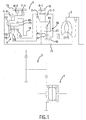
- Fig. 1 is a schematic diagram showing the gear train in a first embodiment of the invention applied to an automatic transmission with six forward speeds and one reverse speed, with the axles shown unfolded in a common plane.
- the automatic transmission is a trans-axle having three axles. More specifically, a torque converter 2 with a lock-up clutch and a planetary gear transmission apparatus 1 are provided on the first axle, a counter gear mechanism 3 is provided on the second axle and a differential gearing 4 is provided on the third axle.
- the automatic transmission is coupled to an engine (not shown) through the torque converter 2 that is provided on the front side of a power transmission path with respect to the planetary gear transmission apparatus 1, and is also coupled to right and left axles (not shown) through the counter gear mechanism 3 and the differential gearing 4 which are provided on the rear side of the power transmission path.
- the planetary gear transmission apparatus 1 comprises a Ravigneaux planetary gear set G and a planetary gear G0 that inputs a reduced rotation into the planetary gear set G.
- the planetary gear set G comprises a small-diameter sun gear S2, a large-diameter sun gear S3, a long pinion P3 that mutually mates and also mates with the large-diameter sun gear S3, a short pinion P2 that mates with the small-diameter sun gear S2, carriers C2 (C3) that support the pair of pinions, and a ring gear R3 that mates with the long pinion P3.
- the planetary gear G0 for reducing rotation is composed of three elements: a sun gear S1, a pinion P1 mating therewith and a carrier C1 that supports pinion P1, and a ring gear R1 that mates with the pinion P1.
- the small-diameter sun gear S2 of the planetary gear set G is coupled to the carrier C1 of the reduction planetary gear G0 by a first clutch C-1 (hereinafter, simply referred to as "C1 clutch”)
- the large-diameter sun gear S3 is coupled to the same carrier C1 of the reduction planetary gear G0 by a third clutch C-3 (hereinafter, simply referred to as “C3 clutch”) and is engagable to a case 10, for stopping, by a first brake B-1 (hereinafter, simply referred to as "B1 brake”)
- the carrier C2 (C3) is coupled to an input shaft 11 by a second clutch C-2 (hereinafter, simply referred to as "C2 clutch) and is engagable to the case 10, for stopping, by a second brake B-2 (hereinafter, simply referred to as "B2 brake”)
- the ring gear R3 is coupled to a counter drive gear 19 as an output element.
- a one-way clutch F-1 is positioned in parallel with the B2 brake.
- the reduction planetary gear G0 is such that the sun gear S1 thereof is anchored to the transmission case 10, the ring gear R1 thereof is coupled to the input shaft 11, the carrier C1 thereof is coupled to the small-diameter sun gear S2 of the planetary gear set G by the C1 clutch, and is coupled to the large-diameter sun gear S3 of the planetary gear set G by the C3 clutch.
- each of the above-mentioned clutches and brakes is provided with a hydraulic servo which is formed by a piston/cylinder mechanism for engaging and disengaging the clutches and brakes with and from the respective friction-engaging members, as well known in the art.
- a hydraulic control apparatus and an electronic control apparatus (not shown)
- the friction-engaging members are engaged and disengaged, and speed changes are accomplished, in accordance with the supply and discharge of a hydraulic pressure to and from each hydraulic servo by a hydraulic pressure control apparatus provided in the transmission case 10, on the basis of the vehicle load within the speed range corresponding to the range selected by the driver.
- FIG. 2 is a table showing the relationship between the action of each solenoid valve in the hydraulic control apparatus and each clutch and brake in the planetary gear transmission apparatus 1, and the speeds attained thereby.
- the mark ⁇ indicates engagement
- the mark ⁇ indicates engagement during engine reduction and a blank indicates disengagement
- the mark ⁇ indicates providing an electric current
- the mark ⁇ indicates the electric current is off.
- a first speed (1ST) of the gear train is attained by automatic engagement of the one-way clutch F-1 that corresponds to engagement of the C1 clutch and the B2 brake.
- rotation from the input shaft 11 that has been braked via the reduction planetary gear G0 is input to the small-diameter sun gear S2 via the C1 clutch, obtains a reaction force from the carrier C2 (C3) stopped by engagement with the one-way clutch F-1, and the braked rotation of the maximum gear ratio of the ring gear R3 is output to the counter drive gear 19.
- a second speed (2ND) is attained by engagement of the C1 clutch and the B1 brake.
- rotation from the input shaft 11, that has been braked via the reduction planetary gear G0 is input to the small-diameter sun gear S2 via the C1 clutch, obtains a reaction force from the large-diameter sun gear S3 stopped by engagement with the B1 brake, and the braked rotation of the ring gear R3 is output to the counter drive gear 19.
- the reduction ratio in this case is smaller than in first speed (1ST).
- a third speed (3RD) is attained by simultaneous engagement of the C1 clutch and the C3 clutch.
- rotation from the input shaft 11 that has been braked via the reduction planetary gear G0 is input simultaneously to the small-diameter sun gear S2 and the large-diameter sun gear S3 via the C1 clutch and the C3 clutch, and the planetary gear set G is directly coupled together.
- the input rotation at both sun gears and the rotation of the ring gear R3 at the same speed are output to the counter drive gear 19 as rotations braked with respect to the rotation of the input shaft 11.
- a fourth speed (4TH) is attained by simultaneous engagement of the C1 clutch and the C2 clutch.
- rotation from the input shaft 11 that has been braked via the reduction planetary gear G0 is input to the sun gear S2 via the C1 clutch, while, on the other hand, unbraked rotation input via the C2 clutch from the input shaft 11 is input to the carrier C2 (C3).
- rotation at an intermediate speed between these two input rotations is output to the counter drive gear 19 as the rotation of the ring gear R3 slightly braked by the rotation of the input shaft 11.
- a fifth speed (5TH) is attained by simultaneous engagement of the C2 clutch and the C3 clutch.
- rotation from the input shaft 11, that has been braked via the reduction planetary gear G0 is input to the sun gear S3 via the C3 clutch, while, on the other hand, unbraked rotation input via the C2 clutch from the input shaft 11 is input to the carrier C2 (C3).
- rotation of the ring gear R3, slightly increased from the rotation of the input shaft 11, is output to the counter drive gear 19.
- a sixth speed (6TH) is attained by engagement of the C2 clutch and the B 1 brake.
- unbraked rotation from the input shaft 11 via the C2 clutch is input only to the carrier C2 (C3), and further increased rotation of the ring gear R3, which obtains a reaction force from the sun gear S3, that is stopped by engagement with the B1 brake, is output to the counter drive gear 19.
- a reverse speed (REV) is attained by engagement of the C3 clutch and the B2 brake.
- REV reverse speed
- a rotation from the input shaft 11, that has been braked via the reduction planetary gear G0, is input to the sun gear S3 through the C3 clutch.
- the result is reverse rotation of a large gear ratio of the ring gear R3, which obtains a reaction force from the carrier C3 stopped by engagement of the B2 brake, is output to the counter drive gear 19.
- the hydraulic control apparatus is composed such that for the C1 clutch, as a first friction element, and the C2 clutch, as a second friction element, hydraulic pressure is supplied through a manual valve 53 from the line pressure oil path L1 as a hydraulic pressure source.
- the C3 clutch, as a third friction element, and the B1 brake, as a fourth friction element, have hydraulic pressure supplied directly from the line pressure oil path L1 in the same manner.
- Switching valves 55 - 59 are provided, on the upstream side of the supply paths L31, L32, L10, L11 and L12 of the respective hydraulic servos 81 - 84, as switching means for cutting off the supply of hydraulic pressure to the friction elements other than the friction elements engaged in order to attain each speed.
- the elements labeled with reference numbers 71 - 74 indicate control means for regulating the pressure supplied to each hydraulic servo.
- the hydraulic pressure regulated through the elements 71 - 74 and the signal pressure output from the elements 71 - 74 is used in the switching operation of the switching valves 55 - 59.
- the control means also serves as an operation means for each of the switching valves 55 - 59.
- Fig. 4 is a circuit diagram showing details of the hydraulic control apparatus.
- the hydraulic pressure circuit comprises a circuit that regulates pressure while exhausting a hydraulic pressure, that is sucked up by an oil pump 51 as a hydraulic pressure generating means and ejected into a line pressure oil path L1, to a drain oil path L9 and a secondary pressure oil path line L2 for the lock-up clutch through a primary regulator valve 52; creates the appropriate line pressure in accordance with the running load of the vehicle; and supplies and exhausts the line pressure to the hydraulic servos 81 - 85 of each friction element with pressure and direction controlled by each valve in the circuit with the line pressure as a reference pressure for control.
- the primary regulator valve 52 comprises a spring-loaded spool and a regulator valve provided with a plunger abutted to the spring-loaded side spool edge.
- the primary regulator valve 52 is provided with an input port connected to the line pressure oil path L1, an output port leading to the secondary pressure oil path L2, and a drain port leading to the intake side of the oil pump via the drain oil path L9.
- direct feedback pressure from the line pressure is applied via an orifice in opposition to a spring force.
- a throttle pressure output by a throttle solenoid valve 76 is applied in the direction of overlapping the spring force.
- the primary regulator valve 52 reduces the level of communication to the drain port and primarily supplies the surplus pressure to the secondary pressure oil path L2.
- the level of communication to the drain port is increased, the drain amount increases and the line pressure in the line pressure oil path L1 is maintained at a predetermined value.
- the line pressure oil path L1 is connected to a modulator valve 54 that supplies the reference pressure for creation of a solenoid signal pressure to each solenoid valve 71 - 75 acting as control means and an operation means and, on the other hand, is connected to each spool edge side receptor part of the B1-C3 cut-off valve 56 and the SLC3 release valve 60 acting as the second switching valve, and is also connected to the input port of the B1-C3 cut-off valve 56.
- the manual valve 53 is a spool valve having seven positions, that can be switched through operation of a switch lever by the vehicle driver, as is known in the art. That is to say, the manual valve 53 has a "P" position that closes the input port connected to the line pressure oil path L1 through the action of the spool; an "R” position that connects the input port to the R range output port, and closes and drains the other output ports; an "N” position that closes the input port relative to all output ports; "D", "4" and “3” positions that connect the input port to the D range output port and drains the R range output port; and a "2" position that connects the input port to both the D range output port and the second D range output port, and drains the R range output port.
- the D range output port of the manual valve 53 is connected, via the D range oil path L3, to the C1 cut-off valve 55 and the input port of the C2 supply relay valve 59 acting as the third switching valve.
- the R range output port is connected to one of the input ports of the shuttle valve 63 on the supply oil path of the B2 brake hydraulic servo 85, and furthermore is connected to the release signal pressure port through the plunger edge receptor part of the primary regulator valve 52.
- the supply path to the C1 clutch hydraulic servo 81 links to the supply path L31 via the input and output ports of the C1 cut-off valve 55 from the D range oil path L3, and is connected to the C1 clutch hydraulic servo 81 by a supply path L31' through the input and output ports of the C1 solenoid valve (SLC1), that acts as a first control means and operation means that regulates pressure on the basis of signals from the electronic control apparatus.
- SLC1 solenoid valve SLC1 solenoid valve
- the C1 solenoid valve 71 comprises a spool valve part that acts as a three port pressure-regulating valve to control the degree of communication of the drain port and the input and output ports by means of a spring-loaded spool, and as a three port linear solenoid valve part in which a solenoid load and a spring load are applied opposite each other similar to applying a solenoid pressure to the non-spring-loaded side edge of the spool.
- the input port of the linear solenoid valve part is connected to the output port of the solenoid modulator valve 54 via the modulator pressure oil path L6, and the output port of the linear solenoid valve part is connected to the signal pressure port of the spool valve part.
- the input port is connected to the output port of the C1 cut-off valve 55 via the supply path L31
- the output port is connected to the C1 clutch hydraulic servo 81 via the supply path L31'
- the feedback port leading to the spring-loaded side spool edge is connected to the oil path on the downstream side of the output port via an orifice.
- the oil path on the downstream side of the output port is further connected to the port of the different-diameter receptor part of the B1-C3 cutoff valve 56.
- a supply path to the C2 clutch hydraulic servo 82 is connected from the D range oil path L3 to the supply path L32 via the input and output ports of the C2 supply relay valve 59 that acts as the third switching valve, and furthermore, is connected to the C2 clutch hydraulic servo 82 via the supply path L32' through the input and output ports of the C2 solenoid valve (SLC2) 72 that acts as a second control means and operating means for regulating pressure on the basis of a signal from the electronic control apparatus.
- the C2 solenoid valve 72 also comprises a spool valve part that acts as a three port pressure-regulating valve that controls the degree of communication of the drain port and the input and output ports by means of a spring-loaded spool, and a three port linear solenoid valve part in which a solenoid load and a spring load are applied opposite each other similar to applying a solenoid pressure to the non-spring-loaded side edge of the spool.
- the input port of the linear solenoid valve part is connected to the output port of the solenoid modulator valve 54 via the modulator pressure oil path L6, and the output port of the linear solenoid part is connected to the signal pressure port of the spool valve part.
- the input port is connected to the output port of the C2 supply relay valve 59 via the supply path L32
- the output port is connected to the C2 clutch hydraulic servo 82 via the supply path L32'.
- the feedback port leading to the spring-loaded side spool edge is connected to the oil path on the downstream side of the output port via an orifice.
- the oil path on the downstream side of the output port is further connected to the signal pressure ports on the spring-loaded side spool edge of the C1 cut-off valve 55, the B1-C3 cut-off valve 56 and the SLC3 release valve 60, and to the signal pressure port on the spool edge of the C2 supply relay valve 59 and the B2 cut-off valve 64.
- a supply path to the C3 clutch hydraulic servo 83 leads from the line pressure oil path L1 along one of the two branches of the supply path L10 via the input and output ports of the B1-C3 cut-off valve 56 that acts as a first switching valve of the first group, leads along the supply path L11 through the input and output ports of the B1 apply relay valve 58, that acts as a second switching valve of the first group, and is connected to the C3 clutch hydraulic servo 83 by the supply path L11' via the input and output ports of the C3 solenoid valve (SLC3) 73 that acts as a third control means and operating means for regulating pressure on the basis of a signal from the electronic control apparatus.
- SLC3 solenoid valve (SLC3) 73 that acts as a third control means and operating means for regulating pressure on the basis of a signal from the electronic control apparatus.
- the C3 solenoid valve 73 also comprises a spool valve part that acts as a three port pressure-regulating valve that controls the degree of communication of the drain port and the input and output ports by means of a spring-loaded spool, and a three port linear solenoid valve part in which a solenoid load and a spring load are applied opposite each other similar to applying a solenoid pressure to the non-spring-loaded side edge of the spool.
- the input port of the linear solenoid valve part is connected to the output port of the solenoid modulator valve 54 via the modulator pressure oil path L6, and the output port of the linear solenoid valve part is connected to the signal pressure port of the spool valve part and is also connected to the spring-loaded side receptor part of the C3 apply relay valve 57 by the signal path L61 via the input and output ports of the SLC3 release valve 60.
- the input port is connected to the above-mentioned supply path L11, and the output port is connected to the C3 clutch hydraulic servo 83 via the supply path L11' and is connected to the port of the different-diameter receptor part of the B2 cut-off valve 64 and the C1 cut-off valve 55 through either the input port or output port of the shuttle valve 62.
- the supply path to the B1 brake hydraulic servo 84 leads from the line pressure oil path L1 along the other of the two branches of the supply path L10 via the input and output ports of the B1-C3 cut-off valve 56, that acts as a first switching valve of the second group and, in this case, leads along the supply path L12 through the input and output ports of the C3 apply relay valve 57, that acts as a second switching valve of the second group, and is connected to the B1 brake hydraulic servo 84 by the supply path L12' via the input and output ports of the B1 solenoid valve (SLB1) 74, that acts as a fourth control means and operating means for regulating pressure on the basis of a signal from the electronic control apparatus.
- SLB1 solenoid valve (SLB1) 74 that acts as a fourth control means and operating means for regulating pressure on the basis of a signal from the electronic control apparatus.
- the B1 solenoid valve 74 in this case also comprises a spool valve part that acts as a three port pressure-regulating valve that controls the degree of communication of the drain port and the input and output ports by means of a spring-loaded spool, and a three port linear solenoid valve part in which a solenoid load and a spring load are applied opposite each other similar to applying a solenoid pressure to the non-spring-loaded side edge of the spool.
- the input port of the linear solenoid part is connected to the output port of the solenoid modulator valve 54 via the modulator pressure oil path L6, and the output port of the linear solenoid part is connected to the signal pressure port of the spool valve part and is also connected to the spring-loaded side receptor part of the B1 apply relay valve 58 by the signal path L62 via the input and output ports of the SLB1 release valve 61.
- the input port is connected to the above-mentioned supply path L12
- the output port is connected to the B1 brake hydraulic servo 84 via the supply path L12' and is connected to the port of the different-diameter receptor part of the B2 cut-off valve 64 and the C1 cut-off valve 55 through the other of the input port and output port of the shuttle valve 62.
- the supply path to the B2 brake hydraulic servo 85 is the supply path of two systems.
- One of the supply paths is composed of an oil path connected to the R range oil path L4 via the shuttle valve 63
- the other of the supply paths is an oil path from the above-mentioned supply path L32 and is composed of an oil path that passes through the shuttle valve 63 and reaches the B2 brake hydraulic servo 85 by means of a supply path linking, in series, the C2 supply relay valve 59, the B2 cut-off valve 64 and the B2 control valve 65 on the supply path.
- the solenoid valve 75 for controlling the C2 supply relay valve 59 is a normally-closed three port on/off valve that opens and closes the input and output ports and the drain port by means of spring-loaded balls. Furthermore, the C2 supply relay valve 59 is a spring-loaded three port switching valve that switches the output port linked to the input port of the B2 cut-off valve 64 to the drain port and input port linked to the D range oil path L3 by means of one spool with a plunger action. In the plunger, a modulator pressure is applied on one end from the solenoid valve 75 and, on the other end, which abuts the spool, an apply pressure to the C2 clutch hydraulic servo 82 is applied.
- the C1 cut-off valve 55 and C3 solenoid valve on the upstream side of the C1 solenoid valve 71, along with the B1-C3 cut-off valve 56 on the upstream side of the B 1 solenoid valve, along with the SLC3 release valve 60 on the downstream side of the C3 solenoid valve, are all made to be the exact same spool-type three port switching valves having an input and output ports and a drain port. They all have a configuration comprising a two-level different-diameter receptor part as the diameter of the spring-loaded edge part is shrunk.
- the signal pressure port leading to the non-spring-loaded side spool edge of each of these valves 55, 56, 60 are all connected to the line pressure oil path L1 as described above.
- the signal pressure port leading to the different-diameter receptor part of the C1 cut-off valve 55 is connected via an orifice to the signal pressure port of the different-diameter receptor part of the B2 cut-off valve 64 and the output port of the shuttle valve 62, and the signal pressure port leading to the receptor part on the spring-loaded side spool edge is connected via an orifice to the supply path L32' of the C2 clutch hydraulic servo 82.
- the signal pressure port leading to the different-diameter receptor part of the B1-C3 cut-off valve 56 is connected via an orifice to the supply path L31' of the C1 clutch hydraulic servo 81, and the signal port leading to the receptor part on the spring-loaded side spool edge is connected via an orifice to the C2 clutch hydraulic servo 82.
- the signal pressure port leading to the different-diameter receptor part of the SLC3 release valve 60 is connected via an orifice to the supply path L12' of the B1 brake hydraulic servo 84, and the signal port leading to the receptor part on the spring-loaded side spool edge is connected to the supply path L32' of the C2 clutch hydraulic servo 82 via an orifice.
- the C3 apply relay valve 57 and the B1 apply relay valve 58 on the downstream side of the B1-C3 cut-off valve 56, along with the SLB1 release valve 61 on the downstream side of the B1 solenoid valve 74, are all made to be the exact same spool-type three port switching valves having an input port, an output port, and a drain port.
- the valves 57, 58, 61 have a configuration in which there is no difference in diameter in the spool.
- the signal pressure port leading to the non-spring-loaded side spool edge of each of the valves 57, 58, 61 are all connected to the modulator pressure oil path L6.
- the signal pressure port leading to the receptor part on the spring-loaded side spool edge of the C3 apply relay valve 57 is connected to the output port of the SLC3 release valve 60 via an orifice.
- the signal pressure port leading to the receptor part on the spring-loaded side spool edge of the B1 apply relay valve 58 is connected to the output port of the SLB1 release valve 61 via an orifice.
- the signal pressure port leading to the receptor part on the spring-loaded side spool edge of the SLB1 release valve 61 is connected to the output port of the SLC3 release valve 60 via an orifice.
- the C2 supply relay valve 59 on the upstream side of the C2 solenoid valve 72, is used as a spool-type three port switching valve having an input port, an output port, and a drain port.
- a plunger On the side opposite the spring-loaded edge part of the spool, a plunger abuts the spool.
- the valve 59 is such that the port leading to the receptor part between the spool and the plunger is connected to the supply path L32' of the C2 clutch hydraulic servo 82, and the port leading to the receptor part on the plunger edge is connected to the output port of the on/off solenoid valve 75.
- the B2 cut-off valve 64 is made to be a spool-type three port switching valve having an input port, an output port, and a drain port. It has a configuration comprising a two-level different-diameter receptor part as the diameter of the non-spring-loaded edge part is shrunk.
- the port of the valve 64 leading to the spool edge receptor part is connected via an orifice to the supply path L32' of the C2 clutch hydraulic servo 82, and the port leading to the different-diameter receptor part is connected via an orifice to the output port of the shuttle valve 62.
- the output port of the B2 cut-off valve 64 is connected to the input port of the B2 control valve 65 through a circuit, the diagram for the detailed structure in between which is omitted.
- the B2 control valve 65 is made to be a spool-type three port switching valve having an input port, an output port, and a drain port.
- the output port is connected to one of the input ports of the shuttle valve 63, while the port leading to the spool edge on the non-input pressure load side is connected to the throttle pressure oil path L7 via an orifice.
- That hydraulic pressure passes through to the input ports of the solenoid valve 73 and the solenoid valve 74 via the C3 apply relay valve 57 and the B1 apply relay valve 58, but solenoid pressure is not applied to the spool valve parts of these valves and, hence, an output of apply pressure to the hydraulic servos 83, 84, corresponding to these solenoid valve 73, 74, and an output of solenoid pressure to the signal paths L61, L62 does not occur.
- the communication relationship is the same in the "P" position of the manual valve 53, although the spool positions differ.
- the hydraulic pressure of the D range oil path L3 via the C1 cut-off valve 55 which is in a communication state in the right side position in the diagram, is supplied to the input port of the C1 solenoid valve 71 on the oil path L3; the hydraulic pressure of the line pressure oil path L1 is supplied to the input port of the B1 solenoid valve 74 and the C3 solenoid valve 73 on the supply path L10, along the path in the above-described "N" position; and the hydraulic pressure of the D range oil path L3 is supplied to the input port of the C2 supply relay valve 59.
- solenoid pressure to the receptor part on the plunger edge of the C2 supply relay valve 59 is not applied because of the signal OFF of the solenoid valve 75, and hydraulic pressure from the oil path L32' to the part that abuts the spool is not applied either. Consequently, the valve 59 is drained by being in the position to the right side in the diagram under only the energizing force of the spring, and does not enter a state in which hydraulic pressure is supplied.
- the apply pressure to the C1 clutch is applied via an orifice to the different-diameter receptor part of the B1-C3 cut-off valve 56, but switching of the B1-C3 cut-off valve 56 does not occur due to the receptor relationship in the valve, so the above-mentioned hydraulic pressure supply relationship is maintained.
- the C2 supply relay valve 59 is positioned to the right side in the diagram, so the connection between the C2 solenoid valve 72 and the D range oil path L3 is mechanically cut off.
- the second speed is attainted by setting the signal to the C1 solenoid valve 71 to OFF and the signal to the B1 solenoid valve 74 to OFF.
- the B1 solenoid valve 74 enters a regulated pressure state in addition to the apply pressure supply state to the above-mentioned C1 clutch hydraulic servo 81, and regulated apply pressure is supplied to the B1 brake hydraulic servo 84.
- the second speed is attained through engagement of the C1 clutch and the maintaining of the B1 brake reaction force.
- the apply pressure to the B1 brake is applied via an orifice to the different-diameter receptor part of the SLC3 release valve 60.
- the apply pressure is applied to the different-diameter receptor part of the C1 cut-off valve 55 via the shuttle valve 62 but, because of the balance in pressures received, switching of the C1 cut-off valve 55 does not occur.
- the apply pressure to the B1 brake is applied to the different-diameter receptor part of the B2 cut-off valve 64, and switching of the B2 cut-off valve 64 to the position on the left side in the diagram occurs, so that the supply of hydraulic pressure to the B2 brake hydraulic servo 85 is mechanically cut off.
- Solenoid pressure is output from the B1 solenoid valve 74 to the signal path L62.
- the pressure is applied to the spring-loaded side receptor part of the B1 apply relay valve 58 via the SLC3 release valve 61 which is in a pass-through state and, because of the relationship of balance between the received pressure and the modulator pressure applied to the spool edge, the B1 apply relay valve 58 switches to the position on the left side in the diagram.
- the supply of hydraulic pressure from the supply path L10 to the C3 solenoid valve 73 is mechanically cut off.
- the third speed is attained by setting the signals to the C1 solenoid valve and to the C3 solenoid valve 73 to OFF.
- the apply pressure supply state to the above-mentioned C1 clutch hydraulic servo 81 remains unchanged, while the C3 solenoid valve 73 enters a regulated pressure state, and the apply pressure of the C3 solenoid valve 73 is supplied to the C3 clutch hydraulic servo 83.
- third speed is attained by simultaneous engagement of the C1 and C3 clutches.
- the apply pressure to the C3 clutch hydraulic servo 83 is also applied to the different-diameter receptor part of the B2 cut-off valve 64 and the different-diameter receptor part of the C1 cut-off valve 55, in the same manner as in the above-mentioned second speed, via the shuttle valve 62, so the same state occurs as in the second speed.
- solenoid pressure is output to the signal path 61 from the C3 solenoid valve 73, and the pressure is applied to the spring-loaded side receptor part of the C3 apply relay valve 57 via the SLC3 release valve 60, which is in a pass-through state, and, because of the relationship of the balance between the received pressure and the modulator pressure applied to the spool edge, the C3 apply relay valve 57 switches to the position on the left side in the diagram.
- the supply of hydraulic pressure from the supply path L10 to the B1 solenoid valve 74 is mechanically cut off.
- the fourth speed is attained by setting the signal to the C1 solenoid valve 71 to OFF, setting the signal to the C2 solenoid valve 72 to OFF, and setting the signal to the solenoid valve (SL1) 75 to ON.
- the apply pressure supply state to the C1 clutch hydraulic servo 81 remains unchanged, while the modulator pressure output by the solenoid valve 75 is applied to the plunger edge receptor part of the C2 supply relay valve 59.
- the valve 59 is pressed by the plunger and switches to the position to the left side in the drawing. Consequently, the hydraulic pressure of the D range oil path L3 is supplied to the C2 solenoid valve 72 by the oil path L32.
- the C2 solenoid valve 72 enters an apply pressure regulated pressure state, and the apply pressure is supplied to the C2 clutch hydraulic servo 82.
- the apply pressure on the one hand, is applied to the receptor part of the spring-loaded edge side of the C1 cut-off valve 55 and, on the other hand, is applied to the spring-loaded side receptor part of the SLC3 release valve 60 and the spring-loaded edge receptor part of the B1-C3 cut-off valve 56.
- the apply pressure is also applied to the receptor part between spools of the C2 supply relay valve 59.
- the B1-C3 cut-off valve 56 when the apply pressure rises as far as the line pressure, switches to the position on the left side in the diagram, and mechanically cuts off the connection between the D range oil path L3 and the B1 solenoid valve 74 with the C3 solenoid valve 73.
- the spool of the C2 supply relay valve 59 when the apply pressure to the C2 clutch hydraulic servo 82 becomes a set pressure lower than the line pressure, switches to the position on the left side in the diagram, and, when the pressure rises to the line pressure, maintains the position on the left side in the diagram.
- the ON signal of the solenoid valve 75 is unnecessary and is returned to OFF with the appropriate timing. That is to say, the signal to the solenoid valve 75 becomes ON only when changing speeds, and is turned OFF in the standing state after completion of the speed change. In this manner, fourth speed is attained by simultaneous engagement of the C1 and C2 clutches.
- the C3 apply relay valve 57 is switched to the position on the left side in the diagram, and the supply of hydraulic pressure from the supply path L10 to the B1 solenoid valve 74 is mechanically cut off. In this manner, fifth speed is attained through the simultaneous engagement of the C2 clutch and the C3 clutch.
- both apply pressures are applied to the spring-loaded side receptor part and the different-diameter receptor part of the SLC3 release valve 60, and by these hydraulic pressures rising as far as the line pressure, the SLC3 release valve 60 switches to the position on the left side in the diagram and mechanically cuts off the connection between the C3 solenoid valve 73 and the C3 apply valve 57. Further, both apply pressures are also applied to the spring-loaded side receptor part and the different-diameter receptor part of the C1 cut-off valve 55. When the hydraulic pressures have risen as far as the line pressure, the C1 cut-off valve 55 switches to the position on the left side in the diagram, and mechanically cuts off the connection between the C1 solenoid valve 71 and the D range oil path L3. However, this action is unrelated to the other valve actions. Accordingly, sixth speed is attained by engagement of the C2 clutch and maintenance of the reaction force of the B1 brake.
- the line pressure of the line pressure oil path L1 is supplied to the input port of the B1-C3 cut-off valve 56, and the hydraulic pressure is supplied, by the normally applied line pressure to the B1 apply relay valve 58 via the B1-C3 cut-off valve 56, which is positioned to the right side in the diagram, to the C3 solenoid valve 73 via the valve 58, which is in a pass-through state, and is supplied to the C3 clutch hydraulic servo 83 from the C3 solenoid valve 73, which is in an apply pressure output state through the signal being OFF.
- reverse speed is attained by engagement of the C3 clutch and maintenance of the reaction force of the B2 brake.
- each of the normally-open solenoid valves 71 - 74 are all in an apply pressure supply state, and the normally-closed solenoid valve (C2 supply relay control valve) 75 is in a solenoid pressure cut-off state.
- the C2 solenoid valve 72 does not enter the apply pressure output state because the input port there is in a drain state via the C2 supply relay valve 59 (drain paths are shown by dashed lines in the diagram), but the other two solenoid valves, namely the C3 solenoid valve 73 and the B1 solenoid valve 74, are in an apply pressure output state.
- the attempt is made for the apply pressure of the C3 solenoid valve 73 to be supplied to the C3 clutch hydraulic servo 83, and the apply pressure of the B1 solenoid valve 74 to be supplied to the B1 brake hydraulic servo 84.
- the C3 apply relay valve 57 is such that the solenoid pressure output by the C3 solenoid valve 73 is applied to the spring-loaded side of the valve 57 via the SLC3 release valve 60.
- the valve 57 switches to the position on the left side in the diagram in opposition to application of the modulator pressure, the line pressure is cut off, and the B1 brake hydraulic servo 84 is switched to drain communication via the C3 apply relay valve 57.
- solenoid pressure is also output from the B1 solenoid valve 74, but the solenoid pressure is cut off to the SLB1 release valve 61, which has been switched to the closed position through application, on the spring-loaded side receptor part, of a solenoid pressure from the C3 solenoid valve 73 applied via the SLC3 release valve 60, and does not reach the spring-loaded side receptor part of the B1 apply relay valve 58, so that switching of the valve 58 does not occur.
- the supply path to the B2 brake hydraulic servo 85 is cut off because the solenoid valve 75, which is normally closed, does not change with respect to its normal status, and because it is drained by the C2 supply release valve 59, an apply pressure supply state does not occur. Accordingly, during the first speed failure, upshifting occurs to the third speed attainment state with the C1 clutch and the C3 clutch simultaneously engaging.
- the C1 clutch hydraulic servo 81 and the B1 brake hydraulic servo 84 are in an apply pressure supply state under the action of the C1 solenoid valve 71 and the B1 solenoid valve 74, but when failure occurs, the C3 solenoid valve 73 attains an apply pressure supply state, excluding the C2 solenoid valve 72, that is mechanically cut off from the hydraulic pressure supply, and, as a result, the same hydraulic pressure state as in the first speed failure occurs.
- the solenoid pressure output from the C3 solenoid valve 73 is applied to the C3 apply relay valve 57 via the SLC3 release valve 60, while, due to the application of this solenoid pressure, the SLB1 release valve 61 is drained and the B1 apply relay valve 58 and B1 solenoid valve 74 are cut off. Accordingly, also during the second speed failure, upshifting occurs to the third speed attainment state with the C1 clutch and the C3 clutch simultaneously engaging.
- the supply path from the C3 solenoid valve 73 to the C3 clutch hydraulic servo 83 is cut off by the B1 apply relay valve 58, which is in a position to the left side in the diagram with solenoid pressure output by the B1 solenoid valve 74 applied via the SLB1 release valve 61, so that even if the C3 solenoid valve 73 is in a control state due to a signal OFF caused by a failure, apply pressure is not supplied to the C3 clutch hydraulic servo 83.
- the hydraulic pressure supply to the B1 brake hydraulic servo 84 is cut off by the SLC3 release valve 60, which is in a position to the left side in the diagram with the solenoid pressure output by the C3 solenoid valve 73 overlappingly applied with the C2 clutch apply pressure and the B1 brake apply pressure, so the pressure does not reach the C3 apply relay valve 57, and the valve continues with the open state maintained.
- the state of the C2 supply relay valve 59 caused by a signal OFF to the solenoid valve 75 at this time is the same as in the fourth speed failure case. Accordingly, during the sixth speed failure, engagement of the C2 clutch and the B1 brake is maintained, and the sixth speed attainment state is maintained.
- solenoid pressure output by the B1 solenoid valve 74 through modulator pressure is cut off by the SLB1 release valve 61 on which solenoid pressure output by the C3 solenoid valve 73 is applied, so there is no effect on the action of the B1 apply relay valve 58. Accordingly, in this case, reverse speed is maintained without regard to failures in each solenoid valve.
- Fig. 5 is a table comparing and contrasting the relationships among the hydraulic pressure supply of each hydraulic servo, the speeds and the action of each valve in the hydraulic control apparatus of the embodiment.
- the drain element that prevents engagement of the C2 clutch is the C2 supply relay valve, indicated by the reference number (5);
- the drain element that prevents engagement of the B2 brake in the second through sixth speeds, and in the restart case is the B2 cut-off valve indicated by the reference number (6);
- the drain elements that prevent engagement of the B1 brake in the third and fifth speeds, and in the restart case, are the C3 apply relay valve indicated by the reference number (4) and the SLB1 release valve;
- the drain element that prevents engagement of the C3 clutch and B1 brake in the fourth speed is the B1-C3 cut-off valve indicated by the reference number (2);
- the drain element that prevents engagement of the C1 clutch in the fifth and sixth speeds is the C1 cut-off valve indicated by the reference number (1); and the drain elements that prevent
- Figs. 6 and 7 show a second embodiment of the invention.
- a portion of the oil path connections in the foregoing first embodiment are changed using the valves 55 - 62, 64, related to fail-safe, and fixation on the low speed side is expanded up to the second speed.
- the relationships of the oil path connections in this circuit are explained below, with emphasis on the points that have been changed. Valves and oil paths that are the same in this embodiment as in the foregoing embodiment are labeled with the same reference numbers, and an explanation of such is omitted here.
- the spring-loaded side receptor part is changed to connection to the D range oil path L3
- the different-diameter receptor part is changed to connection to the supply path of the C3 clutch apply pressure
- the input port is changed to connection to the signal path L62 of the solenoid path of the B1 solenoid valve 74
- the output port is changed to connection to the spring-loaded side receptor part of the B1 apply relay valve 58.
- the input port is changed to connection to the signal path L61 of the solenoid pressure of the C3 solenoid valve 73
- the output port is changed to connection to the spring-loaded side receptor part of the C3 apply relay valve 57
- the port that acts as the drain port is changed to connection to the port that acts as the drain port of the B1 apply relay valve 58 and to the R range oil path L4.
- the oil path connection relationships in attaining each speed in this embodiment differ from the above-described first embodiment only in the reverse range along with the second, third, fifth and sixth speeds of the D range in which solenoid pressure is output from the C3 solenoid valve 73 and the B1 solenoid valve 74. That is to say, in second speed and sixth speed, the solenoid pressure output from the B1 solenoid valve 74 is applied to the spring-loaded side receptor part of the B1 apply relay valve 58 via the SLB1 release valve 61 and, through this, the supply of line pressure to the C3 solenoid valve 73 is cut off.
- the solenoid pressure output from the C3 solenoid valve 73 is applied to the spring-loaded side receptor part of the C3 apply relay valve 57 via the SLC3 release valve 60. Through this, the supply of line pressure to the B1 solenoid valve 74 is cut off.
- the solenoid pressure output by the B1 solenoid valve 74 is applied to the B1 apply relay valve 58 before the apply pressure to the C3 clutch hydraulic servo 83 can rise as far as the line pressure, and the supply of line pressure to the C3 solenoid valve 73 is cut off. Consequently, the SLC1 release valve 61 does not switch, application of solenoid pressure to the B1 apply relay valve 58 output from the B 1 solenoid valve 74 through the release valve is continued, and only the supply of apply pressure to the C1 clutch hydraulic servo 81 and the B1 brake hydraulic servo 84 is effective. Accordingly, in this case the second speed is maintained by the C1 clutch and the B1 brake simultaneously engaging.
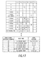
- Fig. 7 shows in table format a comparison and contrasts the action of each valve, the speeds and the supply state of hydraulic pressure to the hydraulic servos in the hydraulic control apparatus.
- solenoid pressure output by the B1 solenoid valve 74 is applied to the B1 apply relay valve 58 before the apply pressure to the C3 clutch hydraulic servo 83 rises to the line pressure.
- the link between the C3 clutch hydraulic servo 83 and the solenoid valve 73 is mechanically cut off.
- the drain element that prevents engagement of the C2 clutch is the C2 supply relay valve indicated by the reference number (5); the drain element that prevents engagement of the B2 brake in the second through sixth speeds and in the restart case is the C2 cut-off valve indicated by the reference number (6); the drain elements that prevent engagement of the B1 brake in the third and fifth speeds are the C3 apply relay valve indicated by the reference number (4) and the SLB1 release valve; the drain element that prevents engagement of the C3 clutch and B1 brake in the fourth speed is the B1-C3 cut-off valve indicated by the reference number (2); the drain element that prevents engagement of the C1 clutch in the fifth and sixth speeds is the C1 cut-off valve indicated by the reference number (1); and the drain elements that prevent engagement of the C3 clutch in the second and sixth speeds and
- Figs. 8 through 10 show a third embodiment of the invention.
- the C2 supply relay valve 59 which is in the form of a relay valve on the supply path 32 of the C2 clutch hydraulic servo 82, that is, in a closed state when no signal pressure is applied, is changed to a cut-off form like the other valves, that is to say is changed to the cutoff valve 59A.
- application of signal pressure to the valve 59A changes.
- the circuit is explained below with emphasis on the points of change. Valves and oil paths that are the same in this embodiment as in the foregoing embodiments are labeled with the same reference numbers, and an explanation of such is omitted.
- the C2 cut-off valve 59A that serves as the third switching valve in this embodiment, has the same form as the other cut-off valves 55, 56, 60.
- the connection relationship between the input and output ports and the supply paths are the same as in the case of the C2 supply relay valve 59 of the foregoing embodiments.
- the signal pressure port linked to the spool edge receptor part of the C2 cut-off valve 59A is connected to the line pressure oil path L1
- the signal pressure port linked to the spring-loaded side receptor part is connected to the supply path L31' of the C1 clutch hydraulic servo 81
- the signal pressure port linked to the different-diameter receptor part is connected to the output port of the shuttle valve 62.
- valve 59A is normally in a communicating state between the input and output ports by the application of a line pressure opposing the spring load, the apply pressure of the clutch C1 applied to the spring-loaded side receptor part overlaps with either the apply pressure of the C3 clutch applied to the different-diameter receptor part or the apply pressure of the B1 brake, and the valve switches, when both apply pressures have risen to the line pressure, causing a cut-off state between the input and output ports.
- the switching order of the C2 cut-off valve 59A and the B1-C3 cut-off valve 56 should be set appropriate to the action during failures, so an orifice Lr is provided as a delay means in the middle of the signal path reaching from the supply path L32' to the spring-loaded side receptor part of the B1-C3 cut-off valve 56.
- the apply pressure to the C1 clutch is applied via an orifice to the spring-loaded side receptor part of the C2 cut-off valve 59A, but from the pressure relationship in the valve 59A, switching does not occur even if the apply pressure rises to the line pressure, and so the valve is in the communicating state, but the C2 solenoid valve 72 does not supply hydraulic pressure to the C2 hydraulic servo 82 because of a signal ON state.
- the C1 solenoid valve 71 and the B1 solenoid valve 74 enter a regulated pressure state, and the apply pressure to the C1 clutch is applied to the spring-loaded side receptor part of the C2 cut-off valve 59A, while the apply pressure of the B1 brake is applied to the different-diameter receptor part of the valve 59A via the shuttle valve 62. Consequently, when both of these apply pressures rise as far as the line pressure, the C2 cut-off valve 59A switches to a cut-off state between the input and output ports in opposition to the application of apply pressure to the spool edge receptor part, and the supply path L32 is mechanically cut off.
- the C1 solenoid valve 71 and the C3 solenoid valve 73 enter a regulated pressure state, and in the C2 cut-off valve 59A, the apply pressure to the C1 clutch is applied to the spring-loaded side receptor part, and the apply pressure of the C3 clutch is applied via the shuttle valve 62 to the different-diameter receptor part. Consequently, the same as in the case of the second speed, when these two apply pressures rise as far as the line pressure, the C2 cut-off valve 59A switches to a cut-off state between the input and output ports in opposition to the application of apply pressure to the spool edge receptor part, and the supply path L32 is mechanically cut off.
- the C2 cut-off valve 59A which is switched due to overlapping application of the apply pressure of the C1 clutch (which is line pressure from the outset) and the apply pressure of the C3 clutch (which rises from the time the failure occurs), is initially in a communicating state, and hydraulic pressure is output to the C2 clutch hydraulic servo 82 from the C2 solenoid valve which enters a regulated pressure state.
- the signal pressure applied to the spring-loaded side receptor part of the B1-C3 cut-off valve 56 is delayed with respect to the rising pressure of the supply path L32' due to the action of the orifice Lr, and consequently raising of the apply pressure of the C3 clutch applied to the different-diameter receptor part of the C2 cut-off valve 59A, via the shuttle valve 62, occurs first, so the C2 cut-off valve 59A switches before the B1-C3 cut-off valve 56 can switch, and its own supply path L32 is mechanically cut off.
- the C1 clutch hydraulic servo 81 and the B1 brake hydraulic servo 84 are in an apply pressure (line pressure) supply state due to the action of the C1 solenoid valve 71 and the B1 solenoid valve 75 from the outset. Consequently, the C2 cut-off valve 59A is cut off by the overlapping application of both of the hydraulic pressures. Midway through this, the apply pressure of the B1 brake is switched to the apply pressure of the C3 clutch, but the control state of the C2 solenoid valve in which the hydraulic pressure supply is mechanically cut off is unrelated to the hydraulic pressure output.
- upshifting occurs to a third speed state wherein the C1 clutch and C3 clutch are simultaneously engaged, the same as in case of the first embodiment.
- the status of the C2 cut-off valve 59A is the same as in the case of failures in the fourth speed. Accordingly, during failures in the fifth speed, no change occurs in the engagement status of the C2 clutch and the C3 clutch, so the fifth speed attainment status is maintained, the same as in the case of the first embodiment.
- the status of the C2 cut-off valve 59A is the same as in the case of failures in the fourth speed. Accordingly, during failures in the sixth speed, no change occurs in the engagement status of the C2 clutch and the B1 brake, so the sixth speed attainment status is maintained, the same as in the case of the first embodiment.
- each of the solenoid valves 71 - 74 is in an apply pressure supply state. Accordingly, the apply pressure supply to the B1 brake hydraulic servo 84 is promptly cut-off by switching of each valve through solenoid pressure, as described in detail in the case of the first speed failure of the foregoing embodiments, through an apply pressure output state from the C2 solenoid valve 72, the C3 solenoid valve 73 and the B1 solenoid valve 74, so that the apply pressure supply to the C3 clutch hydraulic servo 83 is effective.
- the C2 cut-off valve 59A which is switched due to overlapping application of the apply pressure of the C1 clutch (which is line pressure from the outset) and the apply pressure of the C3 clutch (which rises from the time the failure occurs), is initially in a communicating state, and hydraulic pressure is output to the C2 clutch hydraulic servo 82 from the C2 solenoid valve which enters a regulated pressure state.
- the signal pressure applied to the spring-loaded side receptor part of the B1-C3 cut-off valve 56 and the C1 cut-off valve 55 is delayed with respect to the rising pressure of the supply path L32' due to the action of the orifice Lr.
- the supply path on the D range oil path side to the B2 brake hydraulic servo 85 is drained by the B2 control valve 65, and hence does not achieve the apply pressure supply state. Accordingly, the same oil path connections occur as in the above-described failures in second speed, so third speed is attained through simultaneous engagement of the C1 clutch and the C3 clutch, and movement and progress are possible using this speed.
- Fig. 10 is a table comparing and contrasting the relationships among the hydraulic pressure supply of each hydraulic servo, the speeds and the action of each valve in the hydraulic control apparatus of the third embodiment.
- the drain element that prevents engagement of the C2 clutch in the first through third speeds and in the restart case is switched from the C2 supply relay valve 59 of the first embodiment to the C2 cut-off valve 59A as indicated by the reference number (5), but the other drain elements are the same as in the case of the first embodiment.
- Figs. 11 and 12 show a fourth embodiment of the invention.
- the changes in the oil path connections in this circuit and the differences in circuit operation caused by this are the same as the relationships of the second embodiment to the first embodiment.
- Valves and oil paths in this embodiment that are the same as in the foregoing third embodiment are also labeled with the same reference numbers, and an explanation of such is omitted here.
- Fig. 12 is a table comparing and contrasting the relationships among the hydraulic pressure supply of each hydraulic servo, the speeds and the action of each valve in the hydraulic control apparatus of this embodiment.
- the drain element that prevents engagement of the C2 clutch is the C2 cut-off valve indicated by the reference number (5);
- the drain element that prevents engagement of the B2 brake in the second through sixth speeds and in the restart case is the B2 cut-off valve indicated by the reference number (6);
- the drain elements that prevent engagement of the B1 brake in the third and fifth speeds are the C3 apply relay valve indicated by the reference number (4) and the SLB1 release valve;
- the drain element that prevents engagement of the C3 clutch and B1 brake in the fourth speed is the B1-C3 cut-off valve indicated by the reference number (2);
- the drain element that prevents engagement of the C1 clutch in the fifth and sixth speeds is the C1 cut-off valve indicated by the reference number (1); and the drain elements that prevent engagement of the C3 clutch in the second
- Figs. 13 through 15 show a fifth embodiment of the invention.
- the hydraulic pressure circuit primarily differs with respect to each of the foregoing embodiments in that the method is changed to one in which the supply paths of the C3 clutch and the B1 brake are cut off on the downstream side of the solenoid valves 73, 74.
- the relationships of each valve and oil path connection comprising this circuit are described below.
- the respective compositions, functions and mutual connection relationships among the primary regulator valve 52, the manual valve 53 and the modulator valve 54 are the same as in each of the foregoing embodiments, so a description of such is omitted here.
- the supply path with respect to the C1 clutch hydraulic servo 81 has a structure such that the path is connected to the D range oil path L3 via the C1 release valve 55, and on the supply path on the downstream side from the C1 release valve 55, a C1 solenoid valve (SLC1) 71 is provided that acts to regulate the pressure on the basis of a signal from the electronic control apparatus.
- a C1 solenoid valve (SLC1) 71 acts to regulate the pressure on the basis of a signal from the electronic control apparatus.
- the C1 solenoid valve 71 comprises a spool valve part that acts as a three port pressure-regulating valve that controls the degree of communication of the drain port and the input and output ports by means of a spring-loaded spool, and a three port linear solenoid valve part in which a solenoid load and a spring load are applied opposite each other, similar to applying a solenoid pressure to the non-spring-loaded side edge of the spool. Furthermore, the input port of the linear solenoid valve part is connected to the output port of the solenoid modulator valve 54 via the modulator pressure oil path L6, and the output port of the linear solenoid valve part is connected to the signal pressure port of the spool valve part.
- the input port is connected to the output port of the C1 release valve 55, the output port is connected to the C1 clutch hydraulic servo 81 and the feedback port leading to the spool edge on the spring-loaded side is connected to the oil path on the downstream side of the output port via an orifice.
- a supply path to the C2 clutch hydraulic servo 82 is connected to the D range oil path L3 via the C2-B2 supply relay valve 59B.
- a C2 solenoid valve (SLC2) 72 that acts to regulate the pressure on the basis of signals from the electronic control apparatus is provided on the supply path on the downstream side of the C2-B2 supply relay valve 59B.
- the C2 solenoid valve 72 also comprises a spool valve part that acts as a three port pressure-regulating valve that controls the degree of communication of the drain port and the input and output ports by means of a spring-loaded spool, and a three port linear solenoid valve part in which a solenoid load and a spring load are applied opposite each other similar to applying a solenoid pressure to the non-spring-loaded side edge of the spool. Furthermore, the input port of the linear solenoid valve part is connected to the output port of the solenoid modulator valve 54 via the modulator pressure oil path L6, and the output port of the linear solenoid valve part is connected to the signal pressure port of the spool valve part.
- the input port is connected to the output port of the C2-B2 supply relay valve 59B via the supply path L32, the output port is connected to the C2 clutch hydraulic servo 82 and the feedback port leading to the spool edge on the spring-loaded side is connected to the oil path on the downstream side of the output port via an orifice.
- the oil path on the downstream side of the output port is further connected to the signal pressure port on the spool edge of the C2-B2 supply relay valve 59B, and to the signal pressure port on the spring-loaded side spool edge of the C3 release valve 66, the C1 release valve 55 and the B1-C3 release valve 56.
- a supply path to the C3 clutch hydraulic servo 83 is composed with a C3 solenoid valve (SLC3) 73 that acts to regulate the pressure on the basis of signals from the electronic control apparatus provided on the supply path on the downstream side of the oil path L5 connected to the D range oil path L3 and the R range hydraulic pressure L4 via the B1-C3 release valve 56 and the shuttle valve 68.
- SLC3 C3 solenoid valve
- the C3 solenoid valve 73 also comprises a spool valve part that acts as a three port pressure-regulating valve that controls the degree of communication of the drain port and the input and output ports by means of a spring-loaded spool, and a three port linear solenoid valve part in which a solenoid load and a spring load are applied opposite each other similar to applying a solenoid pressure to the non-spring-loaded side edge of the spool.
- the input port of the linear solenoid valve part is connected to the output port of the solenoid modulator valve 54 via the modulator pressure oil path L6, and the output port of the linear solenoid valve part is connected to the signal pressure port of the spool valve part.
- the input port is connected to the above-mentioned supply path L5
- the output port is connected to the input port of the C3 release valve 66
- the feedback port that leads to the spool edge on the spring-loaded side is connected to the oil path on the downstream side of the output port via an orifice.
- the C2 clutch hydraulic servo 83 is connected to the output port of the C3 release valve 66.
- a supply path to the B1 brake hydraulic servo 84 is composed with a B1 solenoid valve (SLB1) 74 that acts to regulate the pressure on the basis of signals from the electronic control apparatus provided on the supply path on the downstream side of the oil path L5.
- the B1 solenoid valve 74 in this case, also comprises a spool valve part that acts as a three port pressure-regulating valve that controls the degree of communication of the drain port and the input and output ports by means of a spring-loaded spool, and a three port linear solenoid valve part in which a solenoid load and a spring load are applied opposite each other similar to applying a solenoid pressure to the non-spring-loaded side edge of the spool.
- the input port of the linear solenoid valve part is connected to the output port of the solenoid modulator valve 54 via the modulator pressure oil path L6, and the output port of the linear solenoid valve part is connected to the signal pressure port of the spool valve part.
- the input port is connected to the above-mentioned supply path L5
- the output port is connected to the input port of the B1 release valve 67
- the feedback port that leads to the spool edge on the spring-loaded side is connected to the oil path on the downstream side of the output port via an orifice.
- the B1 brake hydraulic servo 84 is connected to the output port of the B1 release valve 67.
- the supply path to the B2 brake hydraulic servo 85 is the supply path of two systems.
- One of the supply paths is composed of an oil path connected to the R range oil path L4 via the shuttle valve 63, and the other of the supply paths is a supply path from the oil path L5, with the C2-B2 supply relay valve 59B and the B2 control valve 65B provided in series on the oil path L5, and furthermore has the shuttle valve 63 on its downstream side.
- the solenoid valve 75 for controlling the C2-B2 supply relay valve 59B is a normally-closed three port on/off valve that opens and closes the input and output ports and the drain port by spring-loaded balls.
- the C2-B2 supply relay valve 59B is a six port switching valve that switches the input and output ports and the drain port of each of two spools.
- the solenoid valve 75 is such that the input port thereof is connected to the modulator pressure oil path L6, and the output port is connected to the signal pressure port leading to one of the spool edges of the C2-B2 supply relay valve 59B.
- the C2-B2 supply relay valve 59B is such that one of the input ports is connected to the D range oil path L3, the output port corresponding thereto is connected to the input port of the C2 solenoid valve 72, the other input port is connected to the oil path L5 and the output port corresponding thereto is connected to the input port of the B2 control valve 65B.
- Each of the release valves 55, 56, 66 are the exact same spool-type three port switching valves having an input and output ports and a drain port, and have a configuration comprising a two-level different-diameter receptor surface as the diameter of the spring-loaded edge part is shrunk.
- the signal pressure port leading to the non-spring-loaded side spool edge of each of the release valves 55, 56, 60 is connected to the line pressure oil path L1.
- the input port of the C1 release valve 55 is connected to the D range oil path L3, and the output port is connected to the input port of the C1 solenoid valve 71.
- the signal pressure port leading to the different-diameter receptor part is connected, via an orifice, to the output port of the shuttle valve 62, the input port of which is connected to the supply path of the C3 clutch hydraulic servo 83 and the B1 brake hydraulic servo 84, and the signal pressure port leading to the receptor part on the spring-loaded side spool edge is connected, via an orifice, to the supply path of the C2 clutch hydraulic servo 82.
- the input port of the B1-C3 release valve 56 is connected to the output port of the shuttle valve 68, and the output port is connected to the oil path L5.
- the signal pressure port leading to the different-diameter receptor part is connected via an orifice to the supply path of the C1 clutch hydraulic servo 81, and the signal pressure port leading to the receptor part on the spring-loaded side spool edge is connected via an orifice to the supply path of the C2 clutch hydraulic servo 82.
- the input port of the C3 release valve 66 is connected to the output port side of the C3 solenoid valve 73, and the output port is connected to the C3 clutch hydraulic servo 83 and one of the input ports of the shuttle valve 62.
- the signal pressure port leading to the different-diameter receptor part is connected via an orifice to the supply path of the B1 brake hydraulic servo 84, and the signal port leading to the receptor part of the spring-loaded side spool edge is connected via an orifice to the supply path of the C2 clutch hydraulic servo 82.
- the B1 release valve 67 is a spool-type three port switching valve.
- the signal pressure port leading to the non-spring-loaded side spool edge of the release valve 58 is also connected to the line pressure oil path L1.
- the input port of the valve 67 is connected to the input port of the B1 solenoid valve 74, and the output port is connected to the other of the input ports of the shuttle valve 62.
- the signal pressure port leading to the spring-loaded side spool edge is connected to the supply path of the C3 clutch hydraulic servo 83 via an orifice.
- the B2 control valve 65B is a spool-type three port switching valve with a plunger of different diameters as the load means.
- the input port of the valve 65B is connected to the other of the output ports of the C2-B2 supply relay valve 59B, and the output port is connected to the other input port of the shuttle valve 63.
- the signal pressure port leading to the large diameter side receptor part of the plunger is connected to the output port of the shuttle valve 62, that is connected to the supply path of the C3 clutch hydraulic servo 83 and the B1 brake hydraulic servo 84, the signal pressure port leading to the receptor part on the part side where the plunger and spool abut is connected to the downstream side of the output port via an orifice, and the signal pressure port leading to the receptor part of the spool side is connected to the throttle pressure oil path L7.
- the C2-B2 supply relay valve 59B is a switching valve comprising two spools 59a and 59b of the same diameter having lands at both ends, and a spring 59c that abuts the end of the spool 59b.
- the valve 59B is composed of a valve part provided with an input port that is connected to the D range oil path L3 and is opened and closed by the land at the bottom end of the spool 59b at the bottom of the diagram, a drain port that is opened and closed by the land of the top end of the spool 59b, and an output port positioned between these two ports, in communication to the input port or the drain port between both lands of the spool 59b, and connected to the oil path L32.
- Another valve part is provided with an input port connected to the oil path L5 that is opened and closed by the land on the bottom end of the spool 59a at the top of the diagram, a drain port that is opened and closed by the land of the top end of the spool 59a, and an output port positioned between these two ports, in communication to the input port or the drain port between both lands of the spool 59a, and connected to the input port of the B2 control valve 65B.
- signal pressure ports connected to the oil path L32' linking to the downstream side of the oil path L32 are provided, and in the receptor part of the end side of the spool 59a, a signal pressure port is provided to which the solenoid pressure of the solenoid valve 75 is applied.
- the hydraulic pressure of the D range oil path L3, via the C1 release valve 55, which is in a communicating state in the right side position in the diagram, is supplied to the input port of the C1 solenoid valve 71 on the oil path L3;
- the hydraulic pressure of the line pressure oil path L1, via the B1-C3 release valve 56 that is in the right side position in the diagram, from the shuttle valve 68 is supplied to the input port of the B1 solenoid valve 74 and the C3 solenoid valve 73 on the supply path L5; and the hydraulic pressure of both of the above-described systems is supplied to the two input ports of the C2-B2 supply relay valve 59B.
- solenoid pressure to the receptor part on the spool 59a end side of the C2-B2 supply relay valve 59B is not applied because of the signal OFF of the solenoid valve 75, and hydraulic pressure from the oil path L32' to the part where both spools abut is not applied either. Consequently, the valve 59B is drained by being in the position to the right side in the diagram under only the energizing force of the spring 59c, and does not achieve a state in which hydraulic pressure is supplied.
- the apply pressure to the C1 clutch is applied via an orifice to the different-diameter receptor part of the B1-C3 release valve 56, but switching of the B1-C3 release valve 56 does not occur due to the pressure relationship in the valve 56, so the above-mentioned hydraulic pressure supply relationship is maintained.
- the C2-B2 supply relay valve 59B is positioned to the right side in the diagram, so the connection between the C2 solenoid valve 72 and the D range oil path L3 is mechanically cut off.
- the second speed is attained by setting the signal to the C1 solenoid valve 71 to OFF and the signal to the B1 solenoid valve 74 to OFF.
- the B1 solenoid valve 74 enters a regulated pressure state in addition to the apply pressure supply state to the above-mentioned C1 clutch hydraulic servo 81, and the regulated apply pressure is supplied to the B1 brake hydraulic servo 84 via the B1 release valve 67, which is in a position to the left side in the diagram due to the application of line pressure.
- the second speed is attained through engagement of the C1 clutch and the maintaining of the B1 brake reaction force.
- the apply pressure to the B1 brake is applied via an orifice to the different-diameter receptor part of the C3 release valve 66. Moreover, the apply pressure via the shuttle valve 62 is applied to the different-diameter receptor part of the C1 release valve 55 and the plunger edge receptor part of the B2 control valve 65B. But, because of the balance in pressures received, switching of the C1 release valve 55 does not occur, and in addition, the B2 control valve 65B acts so that the apply pressure to the B1 brake rises as far as a set pressure considerably lower than the line pressure due to the relationship with the throttle pressure on the spool edge, and the connection between the input port of the B2 control valve 65B and the B2 hydraulic servo 85 is mechanically cut off.
- the third speed is attained by setting the signal to the C1 solenoid valve to OFF and the signal to the C3 solenoid valve 73 to OFF.
- the apply pressure supply state to the above-mentioned C1 clutch hydraulic servo 81 remains unchanged, while the C3 solenoid valve 73 enters a regulated pressure state, and the apply pressure thereof is supplied to the C3 clutch hydraulic servo 83 via the C3 release valve 66, which is positioned to the right side in the diagram.
- the third speed is attained by simultaneous engagement of the C1 clutch and the C3 clutch.
- the apply pressure to the C3 clutch hydraulic servo 83 is also applied to the spring-loaded side receptor part of the B1 release valve 67, the plunger-end receptor part of the B2 control valve 65B via the shuttle valve 62, and the C1 release valve 55.
- the B2 control valve 65B switches to the position to the left side in the diagram, and when the apply pressure rises as far as the line pressure, the B1 release valve 67 switches to the position to the right side in the diagram, so the connection between the B2 brake hydraulic servo 82 and the input port of the B2 control valve 65B, and the connection between the B1 solenoid valve 74 and the B1 brake hydraulic servo 84, are mechanically cut off.
- the C2-B2 supply relay valve 59B is in the position to the right side in the diagram, so the connection between the C2 solenoid valve 72 and the D range oil path L3 is mechanically cut off.
- the fourth speed is attained by setting the signal to the C1 solenoid valve 71 to OFF, setting the signal to the C2 solenoid valve 72 to OFF and setting the signal to the solenoid valve (SL1) 75 to ON.
- the apply pressure supply state to the above-mentioned C1 clutch hydraulic servo 81 remains unchanged, while the hydraulic pressure output by the solenoid valve 75 is applied to the non-spring-loaded side spool edge receptor part of the C2-B2 supply relay valve 59B, and the valve 59B switches to the position at the left side in the drawing. Consequently, the hydraulic pressure of the D range oil path L3 is supplied to the C2 solenoid valve 72 by the oil path L32.
- the C2 solenoid valve 72 enters an apply pressure regulated pressure state, and the apply pressure is supplied to the C2 clutch hydraulic servo 82.
- the apply pressure on the one hand, is applied to the receptor part of the spring-loaded edge side of the C1 release valve 55, and, on the other hand, is applied to the spring-loaded side receptor part of the C3 release valve 66 and the spring-loaded edge receptor part of the B1-C3 release valve 56.
- the apply pressure is also applied to the receptor part between spools of the C2-B2 supply relay valve 59B.
- the B1-C3 release valve 56 when the apply pressure rises as far as the line pressure, switches to the position on the left side in the diagram, and mechanically cuts off the connection between the D range oil path L3 and the B1 solenoid valve 74 along with the C3 solenoid valve 73.
- the spool on the bottom in the diagram on the C2-B2 supply relay valve 59B is maintained in the position to the left side in the diagram.
- the ON signal of the solenoid valve 75 becomes unnecessary, and is returned to OFF with the appropriate timing. That is, the signal to the solenoid valve 75 becomes ON only when changing speeds, and is set to OFF in the standing state after completion of a speed change. In this manner, the fourth speed is attained by simultaneous engagement of the C1 and C2 clutches.
- the fifth speed is attained by setting the signal to the C2 solenoid valve (SLC2) 72 to OFF, setting the signal to the C3 solenoid valve (SLC3) 73 to OFF and setting the signal to the solenoid valve (SL1) 75 to ON.
- the apply pressure to the C2 clutch hydraulic servo 82 is similarly applied to the same valves as in the fourth speed
- the apply pressure to the C3 clutch hydraulic servo 83 is similarly applied to the same valves as in the third speed. From the combination relationship of the hydraulic pressure application, both apply pressures are applied to the spring-loaded side receptor part and the different-diameter receptor part of the C1 release valve 55.
- the sixth speed is attained by setting the signal to the C2 solenoid valve 72 to OFF, setting the signal to the B 1 solenoid valve 74 to OFF and setting the signal to the solenoid valve 75 to ON.
- the action through the hydraulic pressure output from the solenoid valve (SL1) 75 is the same as in the above-described fourth and fifth speeds.
- apply pressure to the B1 brake hydraulic servo 84 is similarly applied to the same valves as in second speed.
- both apply pressures are applied to the spring-loaded side receptor part and the different-diameter receptor part of the C3 release valve 66, and by the hydraulic pressures rising as far as the line pressure, the C3 release valve 66 switches to the position on the left side in the diagram and mechanically cuts off the connection between the C3 solenoid valve 73 and the C3 clutch hydraulic servo. Further, both apply pressures are also applied to the spring-loaded side receptor part and the different-diameter receptor part of the C1 release valve 55. When the hydraulic pressures have risen as far as the line pressure, the C1 release valve 55 switches to the position on the left side in the diagram, and mechanically cuts off the connection between the C1 solenoid valve 71 and the D range oil path L3. However, this action is unrelated to the other valve actions. Accordingly, the sixth speed is attained by engagement of the C2 clutch and maintenance of the reaction force of the B1 brake.
- the line pressure of the R range oil path L4 is supplied to the input port of the B1-C3 release valve 56 via the shuttle valve 68, and the hydraulic pressure is supplied to the C3 solenoid valve 73 via the B1-C3 release valve 56, which is positioned to the right side in the diagram by the normally-applied line pressure, and from the C3 solenoid valve 73, which is in an apply pressure output state through the signal being OFF, and is supplied to the C3 clutch hydraulic servo 83 via the C3 release valve 66 which is positioned to the right side in the diagram by the normally-applied line pressure.
- reverse speed is attained by engagement of the C3 clutch and maintenance of the reaction force of the B2 brake.
- each of the normally-open solenoid valves 71 - 74 are all in an apply pressure supply state, and the normally-closed solenoid valve 75 is in a solenoid pressure cut-off state.
- the C2 solenoid valve 72 does not enter the apply pressure output state because the input port thereof is in a drain state via the C2-B2 supply relay valve 59B, but the other two valves, namely the C3 solenoid valve 73 and the B 1 solenoid valve 74, are in an apply pressure output state.
- the attempt is made for the apply pressure of the C3 solenoid valve 73 to be supplied to the C3 clutch hydraulic servo 83 via the C3 release valve 66 which is in a communicating state, and for the apply pressure of the B1 solenoid valve 74 to be supplied to the B1 brake hydraulic servo 84 via the B1 release valve 67 which is in a communicating state.
- the B1 release valve 67 is such that the apply pressure to the C3 clutch hydraulic servo 83 is applied to the spring-loaded side spool edge via an orifice, so the valve 67 switches to the position on the left side in the diagram in opposition to application of the line pressure, the apply pressure is cut off, and the B1 brake hydraulic servo 84 is switched to drain communication.
- the supply path to the B2 brake hydraulic servo 85 is cut off because the solenoid valve 75, which is normally closed, does not change with respect to its normal status, and because this is drained by the C2-B2 supply release valve 59B, an apply pressure supply state does not occur. Accordingly, during the first speed failure, upshifting occurs to the third speed attainment state with the C1 clutch and the C3 clutch simultaneously engaging.
- the B1 brake hydraulic servo 84 When the second speed has been attained, initially the B1 brake hydraulic servo 84 is in an apply pressure supply state under the action of the B1 solenoid valve 74, but when failure occurs, the C3 solenoid valve 73 attains an apply pressure supply state, and, as a result, the same hydraulic pressure state as in the first speed failure occurs.
- the apply pressure of the B1 solenoid valve which is supplied to the B1 brake hydraulic servo via the B1 release valve 67 that is in a communicating state, is cut off by the B1 release valve 67 which is switched to the position to the right side in the diagram by the apply pressure to the C3 clutch hydraulic servo 83 being applied to the spring-loaded side spool edge via an orifice, and the B1 brake hydraulic servo 84 switches to drain communication. Accordingly, during the second speed failure, upshifting also occurs to the third speed attainment state with the C1 clutch and the C3 clutch simultaneously engaging.
- the supply path reaching the B2 brake hydraulic servo 85 via the valve 59B is also in a drain communication state with the supply path L5 cut off by the B1-C3 release valve 56, so the drain communication state of the B2 brake hydraulic servo 85 also does not change. Accordingly, during the fourth speed failure, the apply pressure supply state to the C1 clutch hydraulic servo 81 and the C2 clutch hydraulic servo 82 is maintained without change from the outset, so the fourth speed attainment state is maintained.
- the supply path to the B1 brake hydraulic servo 84 is cut off by the B1 release valve 67 to which the C3 clutch apply pressure is applied and, consequently, even if the B1 solenoid valve 74 is in a control state due to a signal OFF caused by a failure, apply pressure is not supplied to the B1 brake hydraulic servo 84.
- the state of the C2-B2 supply relay valve 59B caused by a signal OFF to the solenoid valve 75 at this time is the same as in the fourth speed failure case. Accordingly, even during the fifth speed failure, no change occurs in the engagement status of the C2 clutch and the C3 clutch, and the fifth speed attainment state is maintained.
- the supply path from the C3 solenoid valve 73 to the C3 clutch hydraulic servo 83 is cut off by the C3 release valve 66 which is in the position to the left side in the diagram with C3 clutch apply pressure and B1 brake apply pressure overlappingly applied, so that even if the C3 solenoid valve 73 is in a control state due to a signal OFF caused by a failure, apply pressure is not supplied to the C3 clutch hydraulic servo 83.
- the state of the C2-B2 supply relay valve 59B caused by a signal OFF to the solenoid valve 75 at this time is the same as in the fourth speed failure case. Accordingly, during the sixth speed failure, engagement of the C2 clutch and the B1 brake is maintained, and the sixth speed attainment state is maintained.
- Fig. 15 is a table comparing and contrasting the relationships among the hydraulic pressure supply of each hydraulic servo, the speeds and the action of each valve in the hydraulic control apparatus of this embodiment.
- the drain element that prevents engagement of the C2 clutch (C-2) is the C2-B2 supply relay valve indicated by the reference number (5);
- the drain element that prevents engagement of the B2 brake in the second through sixth speeds and in the restart case is the B2 control valve indicated by the reference number (6);
- the drain element that prevents engagement of the B1 brake (B-1) in the third and fifth speeds and in the restart case is the B1 release valve indicated by the reference number (4);
- the drain element that prevents engagement of the C3 clutch and B1 brake in the fourth speed is the B1-C3 release valve indicated by the reference number (2);
- the drain element that prevents engagement of the C1 clutch in the fifth and sixth speeds is the C1 release valve indicated by the reference number (1); and the drain element that prevents engagement of the C3 clutch in the
- Figs. 16 and 17 show a sixth embodiment of the invention.
- a structure is employed wherein the C3 release valve 66 switches only by means of the apply pressure to the B1 brake hydraulic servo 84.
- the oil path through which the hydraulic pressure of the C2 clutch hydraulic servo 82 is applied is eliminated.
- an orifice 77 that delays application of signal pressure, is added to the signal pressure oil path through which the apply pressure to the B1 brake hydraulic servo 84 is applied to the spring-loaded side receptor part of the C3 release valve 66.
- the remainder of the circuit structure is the same as in the fifth embodiment, so an explanation of such is omitted here.
- this is prevented by delaying the signal pressure supply to the C3 release valve 66 by means of the orifice 77, so the hydraulic pressure supply to the C3 clutch hydraulic servo 83 occurs in advance of the switching of the C3 release valve 66. Accordingly, with this structure the hydraulic pressure is applied to the B1 release valve 67 first through the hydraulic pressure supply to the C3 clutch hydraulic servo 83, the B1 brake hydraulic servo 84 enters drain communication due to the switching of the B1 release valve 67, and the same circuit switching action as in the above-described first embodiment is obtained.
- Fig. 17 is a table comparing and contrasting the relationships among the hydraulic pressure supply of each hydraulic servo, the speeds and the action of each valve in the hydraulic control apparatus of this embodiment. As is clear from comparing this table with the table in Fig. 15, of the fifth embodiment, the differences between the two are only that the C3 release valve, indicated by the reference number (3) in the figure, is used as the second speed drain element during failures and the difference in the signal pressure during drain operations.
- a control means cum operation means is formed from a pressure regulating valve comprising a spool valve part and a linear solenoid valve part.
- the linear solenoid valve part functions as a control means and the spool valve part functions as the operation means.
- Solenoid pressures output from the linear solenoid valve part of the pressure regulating valve to a switch location having priority based upon the relationship of the order of partial switching operations is used as a signal pressure applied to the priority switching valve, each of the remaining switching valves receive pressure output from the spool valve part.
- control means cum operation means are a unitary valve comprising either a linear solenoid valve or a duty solenoid valve.
- control means and the operation means are separate valves is also possible.
Applications Claiming Priority (4)
| Application Number | Priority Date | Filing Date | Title |
|---|---|---|---|
| JP37181199 | 1999-12-27 | ||
| JP37181199 | 1999-12-27 | ||
| JP2000351227A JP4660917B2 (ja) | 1999-12-27 | 2000-11-17 | 自動変速機の油圧制御装置 |
| JP2000351227 | 2000-11-17 |
Publications (3)
| Publication Number | Publication Date |
|---|---|
| EP1113196A2 true EP1113196A2 (fr) | 2001-07-04 |
| EP1113196A3 EP1113196A3 (fr) | 2002-06-19 |
| EP1113196B1 EP1113196B1 (fr) | 2004-03-10 |
Family
ID=26582357
Family Applications (1)
| Application Number | Title | Priority Date | Filing Date |
|---|---|---|---|
| EP00128125A Expired - Lifetime EP1113196B1 (fr) | 1999-12-27 | 2000-12-22 | Dispositif de commande hydraulique pour une transmission automatique |
Country Status (4)
| Country | Link |
|---|---|
| US (1) | US6494803B2 (fr) |
| EP (1) | EP1113196B1 (fr) |
| JP (1) | JP4660917B2 (fr) |
| DE (1) | DE60008849T2 (fr) |
Cited By (3)
| Publication number | Priority date | Publication date | Assignee | Title |
|---|---|---|---|---|
| EP1039179A3 (fr) * | 1999-03-23 | 2002-06-19 | Aisin Aw Co., Ltd. | Dispositif de commande de pression hydraulique pour transmission automatique |
| CN109404528A (zh) * | 2019-01-24 | 2019-03-01 | 盛瑞传动股份有限公司 | 挡位保持液压控制系统及变速箱 |
| CN111065846A (zh) * | 2017-09-01 | 2020-04-24 | 加特可株式会社 | 自动变速器的选择电磁阀异常诊断装置以及异常诊断方法 |
Families Citing this family (12)
| Publication number | Priority date | Publication date | Assignee | Title |
|---|---|---|---|---|
| JP2003042286A (ja) * | 2001-07-25 | 2003-02-13 | Aisin Aw Co Ltd | 自動変速機の油圧制御装置 |
| JP3849609B2 (ja) * | 2002-08-09 | 2006-11-22 | トヨタ自動車株式会社 | 車両用自動変速機の油圧制御装置 |
| JP4206852B2 (ja) * | 2003-07-02 | 2009-01-14 | トヨタ自動車株式会社 | 車両用自動変速機の油圧制御回路 |
| JP2006207699A (ja) | 2005-01-28 | 2006-08-10 | Aisin Seiki Co Ltd | 自動変速機の油圧制御装置 |
| US7344466B2 (en) * | 2005-08-25 | 2008-03-18 | Hyundai Motor Company | Hydraulic control system of 7-speed automatic transmission for vehicle |
| KR100680641B1 (ko) * | 2005-12-12 | 2007-02-08 | 현대자동차주식회사 | 6속 자동변속기의 유압제어시스템 |
| JP4904873B2 (ja) * | 2006-03-24 | 2012-03-28 | アイシン精機株式会社 | 自動変速機の油圧制御装置 |
| CA2753965C (fr) | 2009-02-27 | 2018-04-17 | Allison Transmission, Inc. | Commande de resolution de panne electro-hydraulique pour transmission a double embrayage |
| JP2011085170A (ja) | 2009-10-14 | 2011-04-28 | Aisin Seiki Co Ltd | 自動変速機の油圧制御装置 |
| US8435148B2 (en) * | 2010-01-11 | 2013-05-07 | GM Global Technology Operations LLC | Hydraulic control system for an automatic transmission having electronic transmission range selection with failure mode control |
| US8500600B2 (en) | 2011-01-10 | 2013-08-06 | GM Global Technology Operations LLC | Hydraulic control system for an automatic transmission having a manual valve with a two gear default strategy |
| JP5321631B2 (ja) * | 2011-03-31 | 2013-10-23 | マツダ株式会社 | 自動変速機の油圧制御装置 |
Family Cites Families (9)
| Publication number | Priority date | Publication date | Assignee | Title |
|---|---|---|---|---|
| US3688607A (en) | 1971-05-26 | 1972-09-05 | Gen Motors Corp | Transmission and control |
| SU714497A1 (ru) | 1976-05-24 | 1980-02-05 | Предприятие П/Я М-5769 | Оптоэлектронное запоминающее устройство |
| DE58905484D1 (de) | 1988-10-26 | 1993-10-07 | Zahnradfabrik Friedrichshafen | Elektrohydraulische steuerung für antriebssysteme von fahrzeugen mit automatischem gangwechsel. |
| JP2897059B2 (ja) * | 1990-03-30 | 1999-05-31 | アイシン精機株式会社 | 自動変速機のシフト制御装置 |
| US5383379A (en) | 1991-06-07 | 1995-01-24 | Honda Giken Kogyo Kabushiki Kaisha | Hydraulic pressure control for automatic transmission |
| JP2876112B2 (ja) * | 1995-06-30 | 1999-03-31 | アイシン・エィ・ダブリュ株式会社 | 自動変速機の制御装置 |
| JP3414658B2 (ja) * | 1998-12-01 | 2003-06-09 | アイシン・エィ・ダブリュ株式会社 | 自動変速機の油圧制御装置 |
| JP4253899B2 (ja) | 1999-02-24 | 2009-04-15 | アイシン・エィ・ダブリュ株式会社 | 自動変速機の油圧制御装置 |
| JP4269399B2 (ja) | 1999-03-23 | 2009-05-27 | アイシン・エィ・ダブリュ株式会社 | 自動変速機の油圧制御装置 |
-
2000
- 2000-11-17 JP JP2000351227A patent/JP4660917B2/ja not_active Expired - Fee Related
- 2000-12-21 US US09/741,165 patent/US6494803B2/en not_active Expired - Fee Related
- 2000-12-22 EP EP00128125A patent/EP1113196B1/fr not_active Expired - Lifetime
- 2000-12-22 DE DE60008849T patent/DE60008849T2/de not_active Expired - Lifetime
Non-Patent Citations (1)
| Title |
|---|
| None |
Cited By (6)
| Publication number | Priority date | Publication date | Assignee | Title |
|---|---|---|---|---|
| EP1039179A3 (fr) * | 1999-03-23 | 2002-06-19 | Aisin Aw Co., Ltd. | Dispositif de commande de pression hydraulique pour transmission automatique |
| US6464610B1 (en) | 1999-03-23 | 2002-10-15 | Aisin Aw Co., Ltd. | Hydraulic pressure control apparatus for automatic transmission |
| CN111065846A (zh) * | 2017-09-01 | 2020-04-24 | 加特可株式会社 | 自动变速器的选择电磁阀异常诊断装置以及异常诊断方法 |
| CN111065846B (zh) * | 2017-09-01 | 2021-06-08 | 加特可株式会社 | 自动变速器的选择电磁阀异常诊断装置以及异常诊断方法 |
| CN109404528A (zh) * | 2019-01-24 | 2019-03-01 | 盛瑞传动股份有限公司 | 挡位保持液压控制系统及变速箱 |
| CN109404528B (zh) * | 2019-01-24 | 2019-05-10 | 盛瑞传动股份有限公司 | 挡位保持液压控制系统及变速箱 |
Also Published As
| Publication number | Publication date |
|---|---|
| DE60008849T2 (de) | 2005-02-03 |
| EP1113196B1 (fr) | 2004-03-10 |
| DE60008849D1 (de) | 2004-04-15 |
| JP4660917B2 (ja) | 2011-03-30 |
| JP2001248724A (ja) | 2001-09-14 |
| US6494803B2 (en) | 2002-12-17 |
| US20010014638A1 (en) | 2001-08-16 |
| EP1113196A3 (fr) | 2002-06-19 |
Similar Documents
| Publication | Publication Date | Title |
|---|---|---|
| JP4253899B2 (ja) | 自動変速機の油圧制御装置 | |
| EP1113196B1 (fr) | Dispositif de commande hydraulique pour une transmission automatique | |
| JP5321631B2 (ja) | 自動変速機の油圧制御装置 | |
| KR100204125B1 (ko) | 유압작동식 변속기의 제어장치 | |
| US8210990B2 (en) | Hydraulic control device for multi-speed automatic transmission | |
| JP4269399B2 (ja) | 自動変速機の油圧制御装置 | |
| JP4094100B2 (ja) | 自動変速機の油圧制御装置 | |
| JP4325105B2 (ja) | 自動変速機の油圧制御装置 | |
| JP2000104811A (ja) | 車両用自動変速機の制御装置 | |
| JP4514020B2 (ja) | 自動変速機の油圧制御装置 | |
| US8632433B2 (en) | Hydraulic control system for automatic transmission and control system for automatic transmission | |
| JP2003049937A (ja) | 自動変速機の油圧制御装置 | |
| JP4480384B2 (ja) | 自動変速機の油圧制御装置 | |
| JP4524938B2 (ja) | 自動変速機の油圧制御装置 | |
| KR100604173B1 (ko) | 자동변속기의 유압제어장치 | |
| KR100714815B1 (ko) | 자동변속기의 유압제어장치 | |
| JPH05203022A (ja) | 自動変速機の油圧制御装置 | |
| JP2003336731A (ja) | 油圧制御装置 | |
| JPS61165055A (ja) | 電子制御式自動変速機の変速制御機構 | |
| JPH11280889A (ja) | 自動変速機の油圧制御装置 | |
| JPS6388358A (ja) | 自動変速機の油圧制御回路 | |
| JP2000035123A (ja) | 自動変速機制御装置 |
Legal Events
| Date | Code | Title | Description |
|---|---|---|---|
| PUAI | Public reference made under article 153(3) epc to a published international application that has entered the european phase |
Free format text: ORIGINAL CODE: 0009012 |
|
| AK | Designated contracting states |
Kind code of ref document: A2 Designated state(s): AT BE CH CY DE DK ES FI FR GB GR IE IT LI LU MC NL PT SE TR |
|
| AX | Request for extension of the european patent |
Free format text: AL;LT;LV;MK;RO;SI |
|
| PUAL | Search report despatched |
Free format text: ORIGINAL CODE: 0009013 |
|
| AK | Designated contracting states |
Kind code of ref document: A3 Designated state(s): AT BE CH CY DE DK ES FI FR GB GR IE IT LI LU MC NL PT SE TR |
|
| AX | Request for extension of the european patent |
Free format text: AL;LT;LV;MK;RO;SI |
|
| 17P | Request for examination filed |
Effective date: 20021128 |
|
| REG | Reference to a national code |
Ref country code: GB Ref legal event code: FG4D |
|
| AKX | Designation fees paid |
Designated state(s): DE FR GB IT |
|
| 17Q | First examination report despatched |
Effective date: 20030303 |
|
| GRAP | Despatch of communication of intention to grant a patent |
Free format text: ORIGINAL CODE: EPIDOSNIGR1 |
|
| GRAS | Grant fee paid |
Free format text: ORIGINAL CODE: EPIDOSNIGR3 |
|
| GRAA | (expected) grant |
Free format text: ORIGINAL CODE: 0009210 |
|
| AK | Designated contracting states |
Kind code of ref document: B1 Designated state(s): DE FR GB IT |
|
| PG25 | Lapsed in a contracting state [announced via postgrant information from national office to epo] |
Ref country code: IT Free format text: LAPSE BECAUSE OF FAILURE TO SUBMIT A TRANSLATION OF THE DESCRIPTION OR TO PAY THE FEE WITHIN THE PRESCRIBED TIME-LIMIT;WARNING: LAPSES OF ITALIAN PATENTS WITH EFFECTIVE DATE BEFORE 2007 MAY HAVE OCCURRED AT ANY TIME BEFORE 2007. THE CORRECT EFFECTIVE DATE MAY BE DIFFERENT FROM THE ONE RECORDED. Effective date: 20040310 |
|
| REG | Reference to a national code |
Ref country code: IE Ref legal event code: FG4D |
|
| REF | Corresponds to: |
Ref document number: 60008849 Country of ref document: DE Date of ref document: 20040415 Kind code of ref document: P |
|
| ET | Fr: translation filed | ||
| PLBE | No opposition filed within time limit |
Free format text: ORIGINAL CODE: 0009261 |
|
| STAA | Information on the status of an ep patent application or granted ep patent |
Free format text: STATUS: NO OPPOSITION FILED WITHIN TIME LIMIT |
|
| 26N | No opposition filed |
Effective date: 20041213 |
|
| PGFP | Annual fee paid to national office [announced via postgrant information from national office to epo] |
Ref country code: GB Payment date: 20121219 Year of fee payment: 13 |
|
| PGFP | Annual fee paid to national office [announced via postgrant information from national office to epo] |
Ref country code: FR Payment date: 20130107 Year of fee payment: 13 |
|
| PGFP | Annual fee paid to national office [announced via postgrant information from national office to epo] |
Ref country code: DE Payment date: 20121219 Year of fee payment: 13 |
|
| REG | Reference to a national code |
Ref country code: DE Ref legal event code: R119 Ref document number: 60008849 Country of ref document: DE |
|
| GBPC | Gb: european patent ceased through non-payment of renewal fee |
Effective date: 20131222 |
|
| REG | Reference to a national code |
Ref country code: FR Ref legal event code: ST Effective date: 20140829 |
|
| REG | Reference to a national code |
Ref country code: DE Ref legal event code: R119 Ref document number: 60008849 Country of ref document: DE Effective date: 20140701 |
|
| PG25 | Lapsed in a contracting state [announced via postgrant information from national office to epo] |
Ref country code: DE Free format text: LAPSE BECAUSE OF NON-PAYMENT OF DUE FEES Effective date: 20140701 |
|
| PG25 | Lapsed in a contracting state [announced via postgrant information from national office to epo] |
Ref country code: GB Free format text: LAPSE BECAUSE OF NON-PAYMENT OF DUE FEES Effective date: 20131222 Ref country code: FR Free format text: LAPSE BECAUSE OF NON-PAYMENT OF DUE FEES Effective date: 20131231 |