EP1113163A2 - Aktivkohlefilter für Brennstoffdampf - Google Patents
Aktivkohlefilter für Brennstoffdampf Download PDFInfo
- Publication number
- EP1113163A2 EP1113163A2 EP00128191A EP00128191A EP1113163A2 EP 1113163 A2 EP1113163 A2 EP 1113163A2 EP 00128191 A EP00128191 A EP 00128191A EP 00128191 A EP00128191 A EP 00128191A EP 1113163 A2 EP1113163 A2 EP 1113163A2
- Authority
- EP
- European Patent Office
- Prior art keywords
- fuel vapor
- chamber
- heat
- adsorbing material
- end wall
- Prior art date
- Legal status (The legal status is an assumption and is not a legal conclusion. Google has not performed a legal analysis and makes no representation as to the accuracy of the status listed.)
- Granted
Links
Images


Classifications
-
- B—PERFORMING OPERATIONS; TRANSPORTING
- B01—PHYSICAL OR CHEMICAL PROCESSES OR APPARATUS IN GENERAL
- B01D—SEPARATION
- B01D53/00—Separation of gases or vapours; Recovering vapours of volatile solvents from gases; Chemical or biological purification of waste gases, e.g. engine exhaust gases, smoke, fumes, flue gases, aerosols
- B01D53/02—Separation of gases or vapours; Recovering vapours of volatile solvents from gases; Chemical or biological purification of waste gases, e.g. engine exhaust gases, smoke, fumes, flue gases, aerosols by adsorption, e.g. preparative gas chromatography
- B01D53/04—Separation of gases or vapours; Recovering vapours of volatile solvents from gases; Chemical or biological purification of waste gases, e.g. engine exhaust gases, smoke, fumes, flue gases, aerosols by adsorption, e.g. preparative gas chromatography with stationary adsorbents
- B01D53/0407—Constructional details of adsorbing systems
- B01D53/0415—Beds in cartridges
-
- F—MECHANICAL ENGINEERING; LIGHTING; HEATING; WEAPONS; BLASTING
- F02—COMBUSTION ENGINES; HOT-GAS OR COMBUSTION-PRODUCT ENGINE PLANTS
- F02M—SUPPLYING COMBUSTION ENGINES IN GENERAL WITH COMBUSTIBLE MIXTURES OR CONSTITUENTS THEREOF
- F02M25/00—Engine-pertinent apparatus for adding non-fuel substances or small quantities of secondary fuel to combustion-air, main fuel or fuel-air mixture
- F02M25/08—Engine-pertinent apparatus for adding non-fuel substances or small quantities of secondary fuel to combustion-air, main fuel or fuel-air mixture adding fuel vapours drawn from engine fuel reservoir
- F02M25/0854—Details of the absorption canister
-
- B—PERFORMING OPERATIONS; TRANSPORTING
- B01—PHYSICAL OR CHEMICAL PROCESSES OR APPARATUS IN GENERAL
- B01D—SEPARATION
- B01D2259/00—Type of treatment
- B01D2259/45—Gas separation or purification devices adapted for specific applications
- B01D2259/4516—Gas separation or purification devices adapted for specific applications for fuel vapour recovery systems
-
- F—MECHANICAL ENGINEERING; LIGHTING; HEATING; WEAPONS; BLASTING
- F02—COMBUSTION ENGINES; HOT-GAS OR COMBUSTION-PRODUCT ENGINE PLANTS
- F02M—SUPPLYING COMBUSTION ENGINES IN GENERAL WITH COMBUSTIBLE MIXTURES OR CONSTITUENTS THEREOF
- F02M25/00—Engine-pertinent apparatus for adding non-fuel substances or small quantities of secondary fuel to combustion-air, main fuel or fuel-air mixture
- F02M25/08—Engine-pertinent apparatus for adding non-fuel substances or small quantities of secondary fuel to combustion-air, main fuel or fuel-air mixture adding fuel vapours drawn from engine fuel reservoir
- F02M2025/0881—Engine-pertinent apparatus for adding non-fuel substances or small quantities of secondary fuel to combustion-air, main fuel or fuel-air mixture adding fuel vapours drawn from engine fuel reservoir with means to heat or cool the canister
Definitions
- This invention relates to improvements in a fuel vapor treatment canister which is adapted to temporarily store therein fuel vapor generated in a fuel tank and the like and to release the stored fuel vapor at certain timings to be burnt in an engine in order to reduce the amount of fuel vapor emitted from the fuel tank and the like of a vehicle provided with the engine.
- fuel vapor treatment canister including fuel vapor adsorbing material (for example, crushed or granulated activated carbon) stored in a casing.
- Fuel vapor generated from a fuel tank is adsorbed by the fuel vapor adsorbing material, and then the adsorbed fuel vapor is desorbed from the fuel vapor adsorbing material at certain timings and carried to a combustion device (for example, combustion chambers of an engine, or a combustibles-burning device of a vehicle equipped with a fuel cell) under the action of air flowing through the fuel vapor adsorbing material.
- a combustion device for example, combustion chambers of an engine, or a combustibles-burning device of a vehicle equipped with a fuel cell
- the fuel vapor treatment canister 101 includes a casing 102C.
- the casing 102C includes a cylindrical casing body 102 which is provided at its one end with a first end wall 103, and at the other end with a second end wall 104.
- the first end wall 103 has a pipe defining therein a communication opening 103a which is in communication with the atmospheric.
- the second end wall 104 has an upper pipe defining therein a fuel vapor inlet opening 104a which is in communication with a fuel tank so that fuel vapor is flown in through the opening 104a.
- the second end wall 104 further has a lower pipe defining therein a fuel vapor outlet opening104b which is in communication with an air intake passage of an intake system of an internal combustion engine (not shown) so that fuel vapor is flown out through the opening 104b.
- a perforated dish-like plate 107 is disposed inside the casing body 102 and located adjacent the second end wall 104.
- the dish-like plate 107 is formed with a plurality of through-holes (not identified) and has a cylindrical flange section (not identified) which is fitted to the inner surface of the casing body 102 and in contact with the second end wall 104 so that a space 106 is defined between the dish-like plate 107 and the second end wall 104.
- a sheet-like filter 108 formed of a non-woven fabric of polyester or a sheet of polyurethane foam is disposed inside the dish-like plate 107 so as to be in contact with the dish-like plate 107.
- a perforated plate 110 is disposed inside the casing body 102 and located adjacent the first end wall 103.
- Two compression springs 112, 112 are disposed between the perforated plate 110 and the first end wall 103 so as to define a space 109 inside the casing body 102.
- a filter 111 similar to the filter 108 is disposed inside and in contact with the perforated plate 110.
- the chamber Ra is filled with a fuel vapor adsorbing material A1a and a heat-accumulative material A2a which is higher in heat conductivity and specific heat than the fuel vapor-adsorbing material A1a which are in a uniformly mixed state.
- heat is generated so as to raise the temperature of the fuel vapor adsorbing material A1a when fuel vapor is adsorbed by the fuel vapor adsorbing material A1a.
- a fuel vapor amount corresponding to fuel vapor adsorbing ability of the fuel vapor adsorbing material A1a increases as the temperature rises.
- the heat generated by the fuel vapor adsorbing material A1a is absorbed by the heat-accumulative material A2a thereby preventing the temperature of the fuel vapor adsorbing material A1a from rising. This prevents the fuel vapor amount corresponding to the fuel vapor adsorbing ability from being lowered.
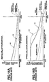
- the concentration of the absorbed fuel vapor takes a mode indicated by curves V1 which indicates the case where the fuel vapor adsorbing material A1a and the heat-accumulative material A2a are disposed in the chamber Ra.
- a curve V2 indicates a case where only the fuel vapor adsorbing material A1a such as activated carbon is disposed in the chamber Ra.
- a curve V3 which indicates the case where the fuel vapor adsorbing material A1a and the heat-accumulative material A2a are disposed in the chamber Ra.
- a curve V4 indicates a case where only the fuel vapor adsorbing material A1a such as activated carbon is disposed in the chamber Ra.
- the fuel vapor residual level (the concentration of the adsorbed fuel vapor) at the respective positions in an axial direction of the canister is low in the case where the fuel vapor adsorbing material A1a and the heat-accumulative material A2a are disposed in the chamber Ra as compared with that in the case where only the fuel vapor adsorbing material A1a is disposed in the chamber Ra.
- Fig. 14B the difference between the concentration of absorbed fuel vapor and the fuel vapor residual level at the side of the first end wall corresponds to the amount of fuel vapor desorbed from the fuel vapor adsorbing material A1a.
- Fig. 14B also reveals that the amount of fuel vapor adsorbed by the fuel vapor adsorbing material A1a at the respective positions in the flow direction of air and fuel vapor in the chamber R1a is large in the case where the fuel vapor adsorbing material A1a and the heat-accumulative material A2a are disposed in the chamber R as compared with that in the case where only the fuel vapor adsorbing material A1a is disposed in the chamber Ra.
- the amount of fuel vapor released from the canister to the atmosphere increases at a time when the amount of fuel vapor adsorbed by the fuel vapor adsorbing material A1a is not so large, in the case where only the fuel vapor adsorbing material A1a is disposed in the chamber Ra as compared with that in case where the fuel vapor adsorbing material A1a and the heat-accumulative material A2a are disposed in the chamber Ra.
- the fuel vapor adsorbing material makes its temperature lowering owing to rapid desorption of fuel vapor from the fuel vapor adsorbing material; however, the temperature lowering can be suppressed upon receiving heat released from the heat-accumulative material. Accordingly, in case that the heat-accumulative material is used mixed with the fuel vapor adsorbing material, the temperature of the fuel vapor adsorbing material can be kept high as compared with a case in which the heat-accumulative material does exist. As a result, a large amount of fuel vapor is abruptly desorbed so as to increase the fuel vapor concentration of intake air to be sucked into the combustion chambers of the engine.
- Japanese Patent Provisional Publication No. 9-112356 discloses also a fuel vapor treatment canister which contains the fuel vapor adsorbing material in the form of a layer and the heat-accumulative material in the form of a layer, in which the two layers are disposed alternate to each other.
- a conventional fuel vapor treatment canister also provides the same disadvantages as those in the above-discussed fuel vapor treatment canister shown in Fig. 13A.
- Another object of the present invention is to provide an improved fuel vapor treatment canister which can effectively prevent an engine from becoming disordered and unburned hydrocarbons from being emitted to the atmosphere while increasing its fuel vapor adsorbing ability, thereby totally reducing emission of hydrocarbons to the atmosphere.
- a further object of the present invention is to provide an improved fuel vapor treatment canister which can effectively prevent a large amount of fuel vapor from being abruptly sucked into an engine while increasing the amount of a fuel vapor adsorbing material disposed in the canister without enlarging the size of the canister.
- a still further object of the present invention is to provide an improved fuel vapor treatment canister having a fuel vapor adsorption chamber and a heat accumulation and fuel vapor adsorption chamber, which is adapted to prevent heat generated in the fuel vapor adsorption chamber from being transmitted to the heat accumulation and fuel vapor adsorption chamber thereby preventing lowering in fuel vapor retaining ability of the fuel vapor adsorbing material in the heat accumulation and fuel vapor adsorption chamber which lowering is owing to temperature rise of the fuel vapor adsorbing material in the heat accumulation and fuel vapor adsorption chamber.
- An aspect of the present invention resides in a fuel vapor treatment canister comprising a casing arrangement having first and second end walls between which first and second chambers are formed.
- the first end wall has a portion defining a first opening in communication with a fuel tank, and a portion defining a second opening in communication with an air intake passage of an engine.
- the second end wall has a portion defining a third opening in communication with atmosphere.
- the first chamber is located closer to the first end wall than the second chamber.
- a first fuel vapor adsorbing material is disposed in the first chamber ,while a second fuel vapor adsorbing material and a heat-accumulative material are disposed in the second chamber.
- the heat-accumulative material is larger in specific heat than the second fuel vapor adsorbing material.
- a second aspect of the present invention resides in a fuel vapor treatment canister comprising a casing having first and second end walls between which an inside space is formed.
- the first end wall has a portion defining a first opening in communication with a fuel tank, and a portion defining a second opening in communication with an air intake passage of an engine.
- the second end wall has a portion defining a third opening in communication with atmosphere.
- the inside space includes first and second chambers.
- the first chamber is located closer to the first end wall than the second chamber.
- a first fuel vapor adsorbing material is disposed in the first chamber, while a second fuel vapor adsorbing material and a heat-accumulative material are disposed in the second chamber.
- the heat-accumulative material is larger in specific heat than the second fuel vapor adsorbing material.
- a third aspect of the present invention resides in a fuel vapor treatment canister comprising a casing having first and second end walls between which an inside space is formed.
- the first end wall has a portion defining a first opening in communication with a fuel tank, and a portion defining a second opening in communication with an air intake passage of an engine.
- the second end wall has a portion defining a third opening in communication with atmosphere.
- the inside space includes first and second chambers.
- the first chamber is located closer to the first end wall than the second chamber.
- a partition wall structure is disposed to divide the inside space into the first and second chambers.
- the partition wall structure has an air permeability and a heat insulating ability higher than that of metal.
- a first fuel vapor adsorbing material is disposed in the first chamber.
- a second fuel vapor adsorbing material and a heat-accumulative material are disposed in the second chamber. The heat-accumulative material is larger in specific heat than the second fuel vapor adsorbing
- a fourth aspect of the present invention resides in a fuel vapor treatment canister comprising a first casing having first and second end walls between which a first chamber is formed.
- the first end wall has a portion defining a first opening in communication with a fuel tank, and a portion defining a second opening.
- a second casing is provided having third and fourth end walls between which a second chamber is formed.
- the third end wall has a portion defining a third opening in communication with the second opening of the first casing.
- the fourth end wall has a portion defining a fourth opening in communication with atmosphere.
- a first fuel vapor adsorbing material is disposed in the first chamber, while a second fuel vapor adsorbing material and a heat-accumulative material are disposed in the second chamber.
- the heat-accumulative material is larger in specific heat than the second fuel vapor adsorbing material.
- the canister 1 of this embodiment is for an automotive vehicle and comprises a casing C formed of a plastic such as nylon or polypropylene.
- the casing C includes a casing body 2 having a circular cross-section.
- the casing body 2 is provided at its one end (right-side end in Fig. 1A) with a first end wall 3, and at the other end (left-side end in Fig. 1A) with a second end wall 4.
- the first end wall 3 has a pipe defining therein a communication opening 3a which is in communication with atmospheric air.
- the second end wall 4 has an upper pipe defining therein a fuel vapor inlet opening 4a which is in communication with a fuel tank so that fuel vapor is flown in through the opening 4a.
- the second end wall 4 further has a lower pipe defining therein a fuel vapor outlet opening 4b which is in communication with an air intake passage of an intake system of an internal combustion engine (not shown) so that fuel vapor is flown out through the opening 4b. It will be understood that intake air to be sucked into the engine flows through the air intake passage.
- Each of the first and second end walls 3 ,4 is fixed to the casing 2 by means of vibration-welding.
- a perforated dish-like plate 7 is disposed inside the casing body 2 and located adjacent the second end wall 4.
- the dish-like plate 7 is formed at its main body section with a plurality of through-holes (not identified) and has a cylindrical flange section (not identified) which is fitted to the inner surface of the casing body 2 and in contact with the second end wall 4 so that a space 6 is defined between the main body section (formed with the through-holes) of the dish-like plate 7 and the second end wall 4.
- a circular sheet-like filter 8 is formed of non-woven fabric of polyester and is disposed inside the dish-like plate 7 so as to be in contact with the main body section of the dish-like plate 7.
- a circular perforated plate 10 formed of plastic is disposed inside the casing body 2 and located adjacent the first end wall 3 in such a manner that the periphery of the perforated plate 10 is in contact with the inner surface of the casing body 2.
- Two compression springs 12, 12 are disposed between the perforated plate 10 and the first end wall 3 so as to define a space 9 inside the casing body 2.
- a filter 11 similar to the filter 8 is disposed inside and in contact with the perforated plate 10.
- the chamber R includes a vapor adsorption chamber R1 and a heat accumulation and vapor adsorption chamber R2. It will be understood that the volume of the chamber R2 is smaller than that of he chamber R1.
- the vapor adsorption chamber R1 is filled with a fuel vapor adsorbing material A1 formed of activated carbon particles.
- the heat accumulation and vapor adsorption chamber R2 is filled with a heat-accumulative and fuel vapor adsorbing material A which includes a fuel vapor adsorbing material A1 and a heat-accumulative material A2 which is higher in heat conductivity and specific heat than the fuel vapor-adsorbing material A1.
- the fuel vapor adsorbing (granular) material A1 and the heat-accumulative (granular) material A2 are respectively formed into circular layers and located alternate in the axial direction of the casing body 2 so that the vapor adsorbing material A1 is located between the layers of the heat-accumulative material A2.
- the heat-accumulative and fuel vapor adsorbing material A is constituted of alternate layers of the fuel vapor adsorbing material A1 and the heat-accumulative material A2.
- Each of the layers of the fuel vapor adsorbing material A1 and the heat-accumulative material A2 has its periphery in contact with the inner surface of the casing body 2 and extends perpendicular to the axis of the casing body 2.
- the heat-accumulative material A2 are aluminum, aluminum alloy, ceramic such as alumina, and stainless steel.
- the perforated plate 10 is pressed leftward in Fig. 1A by the compression springs 12, 12 seated on the first end wall 3, and therefore the fuel vapor adsorbing material A1 and the heat-accumulative material A2 are kept in a tightly filled state under the bias of the compression springs 12, 12, in which the materials A1, A2 are pressed toward the perforated plate 7 at the side of the second end wall 4.
- a ratio in volume between the vapor adsorption chamber R1 and the heat accumulation and vapor adsorption chamber R2 is decided in accordance with kind, size, displacement, operating conditions and the like of the engine for the vehicle to which the fuel vapor treatment canister 1 is installed.
- Fuel vapor from the fuel tank is flown through the fuel vapor inlet opening 4a into the space 6 and then introduced through the dish-like plate 7 and the filter 8 into the vapor adsorption chamber R1 and the heat accumulation and vapor adsorption chamber R2 so that fuel vapor is adsorbed by the fuel vapor adsorbing material A1.
- fuel vapor is first adsorbed by the fuel vapor adsorbing material A1 located at a left-side (side of the second end wall 4) portion of the chamber R1 and then gradually adsorbed by the fuel vapor adsorbing material A1 located at a right-side (side of the first end wall 3) portion of the chamber R1.
- a saturated portion (saturated with fuel vapor) of the fuel vapor adsorbing material A1 moves rightward or toward the first end wall 3 as adsorption of fuel vapor proceeds. More specifically, at the initial period of a process of fuel vapor adsorption, the fuel vapor adsorbing material A1 located near the first end wall 3 does not participate to fuel vapor adsorption; however, as the fuel vapor adsorption proceeds, the fuel vapor adsorbing material A1 gradually becomes participant to fuel vapor adsorption.
- the fuel vapor adsorbing material A1 and the heat-accumulative material A2 are alternately located.
- the heat-accumulative material A2 adsorbs heat generated from the fuel vapor adsorbing material A1 during adsorption of fuel vapor by the fuel vapor adsorbing material A2, thereby softening temperature rise of the fuel vapor adsorbing material A1 itself. This suppresses lowering in fuel vapor adsorbing ability of the fuel vapor adsorbing material A1. Consequently, fuel vapor which flows in from the side of the second end wall 4 can be effectively absorbed by the fuel vapor adsorbing material A1, thereby preventing fuel vapor (not adsorbed) from being released through the communication opening 3a to the atmosphere.
- desorption of fuel vapor adsorbed in the fuel vapor adsorbing material A1 can be effectively accomplished, so that a desorption temperature (at which fuel vapor is desorbed from the fuel vapor adsorbing material A1) of the fuel vapor adsorbing material A1 is kept at a high level as compared with a case where only the fuel vapor adsorbing material A1 is stored in the chamber R of the canister 1, thus lowering a vapor residual level (at which fuel vapor remains not-desorbed in the fuel vapor adsorbing material A1).
- the above-mentioned concentration means the weight of vapor (g) adsorbed per one ml of the fuel vapor adsorbing material A1.
- a gas-permeable partition wall (not shown) may be provided between the chambers R1 and R2, in which the partition wall is formed of a circular and porous metal, plastic or non-woven sheet.
- the partition wall is formed of a material having a low or high heat insulating ability.
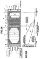
- Fig. 2A illustrates a second embodiment of the fuel vapor treatment canister 1 according to the present invention, which is similar to the first embodiment with the following exception:
- a circular sheet-like filter 14 similar to that 8 is disposed in the chamber R in such a manner that its periphery is in contact with the inner surface of the casing body 2.
- the sheet-like filter 14 divides the chamber R into the vapor adsorption chamber R1 and the heat accumulation and vapor adsorption chamber R2.
- the sheet-like filter 14 serving as a partition wall is thin and therefore is low in heat insulating ability.
- the fuel vapor adsorbing material A1 within the chamber R2 adjacent the filter 14 can adsorb much fuel vapor during adsorption of fuel vapor as compared with that (indicated by a dotted line in Fig. 2B) in case of the first embodiment. Additionally, when air introduced through the opening 3a flows from the side of the first end wall 3 and the side of the second end wall 4, the temperature within the chamber R2 adjacent the filter 14 is kept higher than that in case of the first embodiment. Consequently, as indicated by a mode indicated by a curve M4 in Fig.
- the fuel vapor adsorbing material A within the chamber R2 adjacent the filter 14 can desorb much fuel vapor during desorption of fuel vapor as compared with that (indicated by a dotted line in Fig. 2B) in case of the first embodiment. It will be understood that the same effects as those in the first embodiment can be obtained.
- Figs. 3 to 6 illustrate a third embodiment of the fuel vapor treatment canister 1 according to the present invent ⁇ on, similar to the first embodiment generally with the exception that another vapor adsorption chamber R1A is formed in communication with the vapor adsorption chamber R1 and located parallel with the vapor adsorption chamber R1 and the heat accumulation and fuel vapor adsorption chamber R2.
- the casing C and a casing C1 are formed of the same material as that of the casing C of the first embodiment.
- the casing C and the casing C1 are located parallel with each other and have a rectangular cross-section.
- the casing C and the casing C1 are fixedly connected with each other through a connecting wall 2c and an end connecting wall 2d.
- casing body 2 of the casing C and the casing body 2A of the casing C1 extend leftward over the end connecting wall 2d to form an extended section 2e.
- the cross-sectional area of the inside space of the casing body 2A is about 2 times of that of the casing body 2 as shown in Fig. 4.
- the casing C1 includes the second end wall 4 which is located adjacent the first end wall 3.
- the two compression springs 12, 12 are disposed between the second end wall 4 and the plate 7.
- the first and second end walls 3, 4 are respectively fixed to the casing body 2 and the casing body 2A by welding.
- a bottom end wall 18 is fixed to the extended section 2e of the casing body 2 and the casing body 2A.
- the bottom end wall 18 is rectangular and formed with a plurality of embossments 19 having a rectangular cross-section.
- the embossments 19 are separate from each other to form a gas passage 20.
- a rectangular sheet-like filter 16 is disposed inside the extended section 2e in such a manner that its periphery is in contact with the inner surface of the extended section 2e.
- the filter 16 is supported by the embossments 19 of the bottom end wall 18 so as to contact with the end connecting wall 2d.
- the fuel vapor adsorbing material A1 is filled in the fuel vapor adsorption chamber R1A defined between the filter 8 and the filter 16. Also in this embodiment, the fuel vapor adsorbing material A1 is filled in the fuel vapor adsorption chamber R1 defined between the filter 14 and the filter 16.
- the fuel vapor adsorption chambers R1, R1A are communicated with each other through the filter 16 and the gas passage 20.
- first and second end walls 3, 4, the plates 7, 10 and the filters 8, 11 and 14 are rectangular so that their peripheries are in contact with the inner surfaces of the casing bodies 2, 2A having the rectangular cross-section.
- the fuel vapor adsorbing material A1 and the heat-accumulative material A2 are stored in the heat accumulation and fuel vapor adsorption chamber R2 located adjacent the first end wall 3, and therefore the same effects as those in the first embodiment can be obtained during adsorption of fuel vapor and during desorption of fuel vapor.
- the total space including the fuel vapor adsorption chambers R1, R1A is larger than the space of the heat accumulation and fuel vapor adsorption chamber R2 storing the fuel adsorbing material A1 and the heat-accumulative material A2, and therefore the amount of the heat-accumulative material A2 is less while the fuel vapor adsorbing material A1 are more in the whole chamber R similarly to in the first embodiment.
- Fig. 7 illustrates a fourth embodiment of the fuel vapor treatment canister according to the present invention, which is similar to the second embodiment with the exception that the filter 14 as the partition wall is replaced with a partition wall arrangement S including two filters 14, 14 and an air chamber forming member 21.
- the chamber R is divided into the fuel vapor adsorption chamber R1 and the heat accumulation and fuel vapor adsorption chamber R2 by the partition wall arrangement S.
- the partition wall arrangement S includes the air chamber forming member 21 which is formed of the same plastic as that of the casing body 2.
- the air chamber forming member 21 includes a pair of perforated walls 21a, 21b which are disposed respectively on the side of the chamber R1 and the side of the chamber R2.
- the perforated walls 21a, 21b are spaced from each other by a space maintaining member 21c located between and integral with the perforated walls 21a, 21b.
- Each perforated wall 21a, 21b is formed with a plurality of openings through which air passes.
- the two filters 14, 14 are located respectively in contact with the perforated walls 21a, 21b in such a manner that the air chamber forming member 21 is located between the filters 14, 14.
- the chamber R1 and the chamber R2 are divided by the partition wall arrangement S having heat insulating ability and air permeability, while the chamber R1 and the chamber R2 are divided by the filter 14 in the second embodiment.
- the partition wall arrangement S possessing heat insulating ability and air permeability is disposed between the chamber R1 and the chamber R2 so as to allow gas to flow between the chamber R1 and the chamber R2 but to prevent heat from being transmitted between the chamber R1 and the chamber R2. Consequently, the temperature of the fuel vapor adsorbing material A1 within the chamber R2 can be prevented from rising while preventing the fuel vapor adsorbing material A1 within the chamber R2 from lowering in fuel vapor retaining ability.
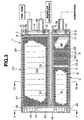
- Fig. 8 illustrates a fifth embodiment of the fuel vapor treatment canister 1 according to the present invention, which is similar to the first embodiment with the exception that the heat accumulation and fuel vapor adsorption chamber R2 filled with the fuel vapor adsorbing material A1 and the heat-accumulative material A2 is removed from the casing C and formed in another casing C2 which is independent from the casing C.
- the casing C is formed with only the fuel vapor adsorption chamber R1 which is defined between the filter 8 and the filter 11 and filled with the fuel vapor adsorbing material A1.
- the casing C2 includes a casing body 2B which is provided with a first end wall 25 and a second end wall 26.
- the first end wall 25 is fixed to one (left-side) end of the casing body 2B and has a pipe defining a communication opening 25a which is in communication with the opening 3a of the first end wall 3 of the casing C through a pipe 27.
- the second end wall 26 is fixed to the other (right-side) end of the casing body 2B and has a pipe defining a communication opening 26a which is in communication with the atmosphere.
- the perforated plate 10 and the filter 11 are disposed adjacent the first end wall 25 in such a manner as to define a space between the perforated plate 10 and the first end wall 25.
- the peripheries of the perforated plate 10 and the filter 11 are in contact with the inner surface of the casing body 2B.
- the perforated plate 7 and the filter 8 are disposed adjacent the second end wall 26 in such a manner as to define a space between the perforated plate 7 and the second end wall 26.
- the peripheries of the perforated plate 7 and the filter 8 are in contact with the inner surface of the casing body 2B.
- the heat accumulation and fuel vapor adsorption chamber R2 is defined between the filter 8 and the filter 11 and inside the casing body 2B.
- the chamber R2 is filled with the fuel vapor adsorbing material A1 and the heat-accumulative material A2 which are formed into the form of a layer and located alternate to each other.
- Fig. 9 illustrates a sixth embodiment of the fuel vapor treatment canister 1 according to the present invention, which is similar to the third embodiment with the exception that the filter 14 for separating the heat accumulation and fuel vapor adsorption chamber R2 from the fuel vapor adsorption chamber R1 has a thickness considerably larger than that of the filter 14 in the third embodiment.
- the filter 14 of this embodiment serves as a partition wall having heat insulating ability and air permeability. This can prevent heat transmission from the fuel vapor adsorption chamber R1 to the heat accumulation and fuel vapor adsorption chamber R2.
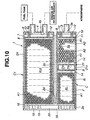
- Fig. 10 illustrates a seventh embodiment of the fuel vapor treatment canister 1 according to the present invention, which is similar to the third embodiment with the exception that the filter 14 for dividing the fuel vapor adsorption chamber R1 and the heat accumulation and fuel vapor adsorption chamber R2 is replaced with the partition wall arrangement S used in the fourth embodiment.
- the partition wall arrangement S divides the inside space of the casing body 2A into the fuel vapor adsorption chamber R1 and the heat accumulation and fuel vapor adsorption chamber R2. As shown, the fuel vapor adsorbing material A1 is filled in the chamber R1, while the fuel vapor adsorbing material A1 and the heat-accumulative material A2 is filled in a mixed state in the chamber R2.
- the partition wall arrangement S of this embodiment includes the air chamber forming member 21 which is formed of the same plastic as that of the casing body 2.
- the air chamber forming member 21 includes a pair of the perforated walls 21a, 21b which are disposed respectively on the sides of the chamber R1 and the chamber R2.
- the perforated walls 21a, 21b are spaced from each other by the space maintaining member 21c located between and integral with the perforated walls 21a, 21b.
- Each perforated wall 21a, 21b is formed with a plurality of openings through which air passes.
- the two filters 14, 14 are located respectively in contact with the perforated walls 21a, 21b in such a manner that the air chamber forming member 21 is located between the filters 14, 14.
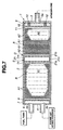
- Fig. 11 illustrates an eighth embodiment of the fuel vapor treatment canister according to the present invention, which is similar to the third embodiment with the exception that only the heat accumulation and fuel vapor adsorption chamber R2 is formed inside the casing C without forming the fuel vapor adsorption chamber R1.
- the chamber R2 is formed between the filter 16 and the filter 11 and inside the casing C, and filled with the vapor fuel adsorbing material A1 and the heat-accumulative material A2 which are formed into a layer and located alternate to each other.
- This embodiment prevents heat transmission from the fuel vapor adsorption chamber R1A to the heat accumulation and fuel vapor adsorption chamber R2 by a partition wall arrangement constituted by the bottom end wall 18 and the filter 16. Consequently, fuel vapor remaining in the fuel vapor adsorbing material A1 within the chamber R1A and the chamber R2 can be prevented from releasing through the communication opening 3a in case that the amount of air for desorbing fuel vapor is insufficient.
- Fig. 12 illustrates a ninth embodiment of the fuel vapor treatment canister 1 according to the present invention, which is similar to the eighth embodiment with the exception that the heat accumulation and fuel vapor adsorption chamber R2 filled with the fuel vapor adsorbing material A1 and the heat-accumulative material A2 is replaced with a fuel vapor adsorption chamber R1B filled with the fuel vapor adsorbing material A1 and formed in another casing C3 which is independent from the casing C.
- the casing C is formed with only the fuel vapor adsorption chamber R1B which is defined between the filter 11 and the filter 16 and filled with the fuel vapor adsorbing material A1.
- the casing C3 is similar to the casing 2B in the fifth embodiment and includes a casing body 2C which is provided with the first end wall 25 and the second end wall 26.
- the first end wall 25 is fixed to one (left-side) end of the casing body 2C and has the pipe defining the communication opening 25a which is in communication with the opening 3a of the first end wall 3 of the casing C through the pipe 27.
- the second end wall 26 is fixed to the other (right-side) end of the casing body 2C and has a pipe defining the communication opening 26a which is in communication with the atmosphere.
- the perforated plate 10 and the filter 11 are disposed adjacent the first end wall 25 in such a manner as to define the space between the perforated plate 10 and the first end wall 25.
- the peripheries of the perforated plate 10 and the filter 11 are in contact with the inner surface of the casing body 2C.
- the perforated plate 7 and the filter 8 are disposed adjacent the second end wall 26 in such a manner as to define a space between the perforated plate 7 and the second end wall 26.
- the peripheries of the perforated plate 7 and the filter 8 are in contact with the inner surface of the casing body 2C.
- the heat accumulation and fuel vapor adsorption chamber R2 is defined between the filter 8 and the filter 11 and filled with the fuel vapor adsorbing material A1 and the heat-accumulative material A2 which are in a mixed state.
- the materials A1, A2 may be replaced with a honeycomb-shaped heat-accumulative and fuel vapor adsorbing material prepared by mixing the fuel vapor adsorbing material matrix particles or powder (such as activated carbon particles or powder) with the heat-accumulative material particle or powder and binder, and then by molding the mixed particles or powders into the honeycomb shape, so that the fuel vapor adsorbing material matrix particles or powder and the heat-accumulative material particle or powder are contained in a dispersed state in the honeycomb-shaped heat-accumulative and fuel vapor adsorbing materials.
- a honeycomb-shaped heat-accumulative and fuel vapor adsorbing material prepared by mixing the fuel vapor adsorbing material matrix particles or powder (such as activated carbon particles or powder) with the heat-accumulative material particle or powder and binder, and then by molding the mixed particles or powders into the honeycomb shape, so that the fuel vapor adsorbing material matrix particles or powder and the heat-accumulative material particle or powder are contained in a dis
- the fuel vapor treatment canister has the fuel vapor adsorption chamber and the heat accumulation and fuel vapor adsorption chamber which are located respectively at the side of fuel vapor inlet and outlet openings and the side of the communication opening in communication with the atmosphere.
- the fuel vapor adsorbing material is disposed in the fuel vapor adsorption chamber, while the fuel vapor adsorbing material and the heat-accumulative material are disposed in the heat accumulation and fuel vapor adsorption chamber.
- the fuel vapor adsorbing material within the heat accumulation and fuel vapor adsorption chamber is prevented from its temperature rise so that fuel vapor adsorption in the chamber can be securely accomplished, thereby effectively preventing release of fuel vapor to the atmosphere.
- the fuel vapor adsorbing material in the chamber is prevented from its temperature lowering owing to the heat release action of the heat-accumulative material in the chamber, so that desorption of fuel vapor from the fuel vapor adsorbing material can be effectively carried out thereby lowering the fuel vapor residual level after the fuel vapor desorption. Accordingly, adsorption of fuel vapor at the next operational (adsorption-desorption) cycle can be ensured.
- the amount of the heat-accumulative material used in the canister can be reduced while increasing the amount of the fuel vapor adsorbing material used in the canister without increasing the size of the casing of the canister.
- the fuel vapor adsorbing ability of the canister can be increased without large-sizing the canister.
- the partition wall may be provided between the fuel vapor adsorption chamber and the heat accumulation and fuel vapor adsorption chamber, or otherwise the fuel vapor adsorption chamber and the heat accumulation and fuel vapor adsorption chamber may be formed respectively in the separate casings, so as to prevent heat transmission from the fuel vapor adsorption chamber to the heat accumulation and fuel vapor adsorption chamber. Consequently, the fuel vapor adsorbing material in the heat accumulation and fuel vapor adsorption chamber can be prevented from its temperature rise even though the temperature of the fuel vapor adsorbing material in the fuel vapor adsorption chamber rises.
Applications Claiming Priority (4)
| Application Number | Priority Date | Filing Date | Title |
|---|---|---|---|
| JP37515199 | 1999-12-28 | ||
| JP37515199 | 1999-12-28 | ||
| JP2000386086A JP3995881B2 (ja) | 1999-12-28 | 2000-12-19 | 蒸発燃料処理用のキャニスタ |
| JP2000386086 | 2000-12-19 |
Publications (3)
| Publication Number | Publication Date |
|---|---|
| EP1113163A2 true EP1113163A2 (de) | 2001-07-04 |
| EP1113163A3 EP1113163A3 (de) | 2002-01-09 |
| EP1113163B1 EP1113163B1 (de) | 2005-10-12 |
Family
ID=26582665
Family Applications (1)
| Application Number | Title | Priority Date | Filing Date |
|---|---|---|---|
| EP00128191A Expired - Lifetime EP1113163B1 (de) | 1999-12-28 | 2000-12-21 | Aktivkohlefilter für Brennstoffdampf |
Country Status (4)
| Country | Link |
|---|---|
| US (1) | US6503301B2 (de) |
| EP (1) | EP1113163B1 (de) |
| JP (1) | JP3995881B2 (de) |
| DE (2) | DE60023094T2 (de) |
Cited By (11)
| Publication number | Priority date | Publication date | Assignee | Title |
|---|---|---|---|---|
| US6540815B1 (en) | 2001-11-21 | 2003-04-01 | Meadwestvaco Corporation | Method for reducing emissions from evaporative emissions control systems |
| DE10203959A1 (de) * | 2002-02-01 | 2003-08-14 | Delphi Technologies Inc N D Ge | Speichervorrichtung |
| WO2004007939A1 (en) * | 2002-07-16 | 2004-01-22 | Mahle Tennex Corporation | Fuel vapor treatment device |
| WO2004036024A1 (en) * | 2002-10-17 | 2004-04-29 | Dayco Fuel Management S.P.A. | Temporary vehicle fuel vapour accumulator |
| EP1582731A1 (de) * | 2004-03-30 | 2005-10-05 | Mahle Tennex Corporation | Kraftstoffdampfsammelbehälter |
| EP1906001A2 (de) * | 2006-09-13 | 2008-04-02 | MAHLE Filter Systems Japan Corporation | Kanister |
| US7604691B2 (en) | 2003-06-28 | 2009-10-20 | Mable Filtersysteme GmbH | Adsorption filter for fuel vapors |
| ITUB20155816A1 (it) * | 2015-11-23 | 2017-05-23 | Fca Italy Spa | Canister per un serbatoio di combustibile di autoveicolo |
| US9732649B2 (en) | 2012-10-10 | 2017-08-15 | Ingevity South Carolina, Llc | Evaporative fuel vapor emission control systems |
| US10960342B2 (en) | 2012-10-10 | 2021-03-30 | Ingevity South Carolina, Llc | Evaporative fuel vapor emission control systems |
| US11732680B2 (en) | 2017-06-19 | 2023-08-22 | Ingevity South Carolina, Llc | Evaporative fuel vapor emission control systems |
Families Citing this family (48)
| Publication number | Priority date | Publication date | Assignee | Title |
|---|---|---|---|---|
| DE19952092C1 (de) * | 1999-10-29 | 2000-10-26 | Daimler Chrysler Ag | Aktivkohlefilter |
| JP3788152B2 (ja) * | 1999-12-28 | 2006-06-21 | 日産自動車株式会社 | 内燃機関のキャニスタ |
| JP3995881B2 (ja) * | 1999-12-28 | 2007-10-24 | 株式会社マーレ フィルターシステムズ | 蒸発燃料処理用のキャニスタ |
| WO2001062367A1 (en) * | 2000-02-22 | 2001-08-30 | Norit Nederland B.V. | Process for the adsorption of organic vapours from gas mixtures containing them |
| JP3727224B2 (ja) * | 2000-05-15 | 2005-12-14 | 愛三工業株式会社 | キャニスタ |
| US7008470B2 (en) * | 2000-12-25 | 2006-03-07 | Aisan Kogyo Kabushiki Kaisha | Canister |
| JP3892385B2 (ja) * | 2002-10-22 | 2007-03-14 | 株式会社デンソー | キャニスタ用フィルタ |
| EP1471246A1 (de) * | 2003-04-23 | 2004-10-27 | Delphi Technologies, Inc. | Vorrichtung zur Behandlung von verdampftem Brennstoff |
| JP2005016329A (ja) * | 2003-06-24 | 2005-01-20 | Nissan Motor Co Ltd | 蒸発燃料処理装置及びそれを用いた内燃機関の制御装置 |
| JP4165641B2 (ja) * | 2003-06-30 | 2008-10-15 | 株式会社Roki | キャニスタ |
| ATE394591T1 (de) * | 2003-07-30 | 2008-05-15 | Delphi Tech Inc | Vorrichtung zur behandlung von verdampftem brennstoff |
| US7132011B2 (en) * | 2003-09-02 | 2006-11-07 | Entegris, Inc. | Reactive gas filter |
| DE10361090B3 (de) * | 2003-12-22 | 2005-06-16 | Helsa-Werke Helmut Sandler Gmbh & Co. Kg | Zusatzfilterelement |
| JP2005233106A (ja) | 2004-02-20 | 2005-09-02 | Mahle Tennex Corp | キャニスタ |
| US20050229787A1 (en) * | 2004-04-14 | 2005-10-20 | Meiller Thomas C | Evaporative emissions canister partition |
| US8313546B2 (en) * | 2004-08-20 | 2012-11-20 | Cantwell Jay S | Fluid flow filter |
| WO2006022329A1 (ja) * | 2004-08-26 | 2006-03-02 | Kuraray Chemical Co., Ltd | 蒸散燃料ガス吸着材及び蒸散燃料ガス捕集装置、並びに活性炭及びその製造方法 |
| DE102004063434B4 (de) * | 2004-12-23 | 2009-03-19 | Mann+Hummel Innenraumfilter Gmbh & Co. Kg | Aktivkohleformkörper, Verfahren zu dessen Herstellung und dessen Verwendung |
| US7717652B2 (en) * | 2005-01-18 | 2010-05-18 | Makino, Inc. | Tool with selectively-biased member having an adjustment feature |
| JP2006207485A (ja) * | 2005-01-28 | 2006-08-10 | Aisan Ind Co Ltd | キャニスタ |
| US7841321B2 (en) | 2005-01-28 | 2010-11-30 | Aisan Kogyo Kabushiki Kaisha | Canister and method of manufacturing the same |
| US7350511B1 (en) | 2005-07-18 | 2008-04-01 | Walbro Engine Management, L.L.C. | Fuel vapor control system |
| JP4522967B2 (ja) * | 2006-03-31 | 2010-08-11 | 愛三工業株式会社 | キャニスタ |
| US20090178566A1 (en) * | 2006-05-10 | 2009-07-16 | Meadwestvaco Corporation | Honeycomb adsorbents for vapor recovery systems |
| US8246729B2 (en) * | 2006-08-03 | 2012-08-21 | Dytech—Dynamic Fluid Technologies S.p.A. | Fuel vapour adsorbing device |
| CN101210910B (zh) * | 2006-12-31 | 2011-03-09 | 同方威视技术股份有限公司 | 气体过滤缓冲一体装置 |
| JP2008303846A (ja) | 2007-06-11 | 2008-12-18 | Mahle Filter Systems Japan Corp | キャニスタ |
| US20090084362A1 (en) * | 2007-09-28 | 2009-04-02 | Wing Chan | Catalyst material for evaporative emission control system |
| US8156924B2 (en) * | 2007-10-17 | 2012-04-17 | Kohler Co. | Systems and methods for regulating purge flow rate in an internal combustion engine |
| DE102007056675A1 (de) * | 2007-11-24 | 2009-05-28 | Dr. Ing. H.C. F. Porsche Aktiengesellschaft | Kraftfahrzeug |
| US8028681B1 (en) * | 2008-10-16 | 2011-10-04 | George M. Pifer | Fuel vaporization apparatus and method for use in combustion engines |
| JP5242360B2 (ja) * | 2008-12-11 | 2013-07-24 | 愛三工業株式会社 | 蒸発燃料処理装置 |
| DE102009057564A1 (de) * | 2009-12-09 | 2011-06-16 | Mahle International Gmbh | Aktivkohlefilter |
| JP5301482B2 (ja) * | 2010-02-18 | 2013-09-25 | 愛三工業株式会社 | キャニスタ |
| WO2011109634A1 (en) * | 2010-03-03 | 2011-09-09 | Kohler Co. | System and method for carburetor venting |
| JP2012007501A (ja) * | 2010-06-23 | 2012-01-12 | Mahle Filter Systems Japan Corp | キャニスタ |
| JP2012225167A (ja) * | 2011-04-15 | 2012-11-15 | Aisan Industry Co Ltd | 蒸発燃料処理装置 |
| JP5770040B2 (ja) * | 2011-07-28 | 2015-08-26 | 愛三工業株式会社 | 蒸発燃料処理装置 |
| JP5819722B2 (ja) * | 2011-12-26 | 2015-11-24 | 愛三工業株式会社 | 蒸発燃料処理装置 |
| JP6017167B2 (ja) * | 2012-04-06 | 2016-10-26 | 愛三工業株式会社 | トラップキャニスタ |
| JP5972669B2 (ja) * | 2012-05-30 | 2016-08-17 | 愛三工業株式会社 | 蒸発燃料処理装置 |
| JP2014234717A (ja) * | 2013-05-31 | 2014-12-15 | 株式会社マーレ フィルターシステムズ | キャニスタ |
| KR101442071B1 (ko) * | 2013-12-10 | 2014-11-04 | 코리아에프티 주식회사 | 자동차용 가스 흡착수단 |
| JP6376106B2 (ja) * | 2015-11-10 | 2018-08-22 | マツダ株式会社 | キャニスタ |
| JP6507092B2 (ja) * | 2015-12-17 | 2019-04-24 | フタバ産業株式会社 | 蒸発燃料処理装置 |
| JP6639217B2 (ja) * | 2015-12-17 | 2020-02-05 | 株式会社マーレ フィルターシステムズ | キャニスタ |
| JP6347422B2 (ja) * | 2016-12-09 | 2018-06-27 | マツダ株式会社 | 蒸発燃料処理装置 |
| JP6725483B2 (ja) * | 2017-12-20 | 2020-07-22 | フタバ産業株式会社 | キャニスタ |
Citations (1)
| Publication number | Priority date | Publication date | Assignee | Title |
|---|---|---|---|---|
| JPH09112356A (ja) | 1995-10-12 | 1997-04-28 | Tenetsukusu:Kk | 蒸発燃料処理用のキャニスタ |
Family Cites Families (28)
| Publication number | Priority date | Publication date | Assignee | Title |
|---|---|---|---|---|
| US3730158A (en) * | 1971-07-28 | 1973-05-01 | Gen Motors Corp | Canister for evaporation loss control |
| US3844739A (en) * | 1972-10-05 | 1974-10-29 | Dow Chemical Co | Apparatus and method for the prevention of evaporative loss of mixed organic liquids |
| JPS5610318A (en) * | 1979-07-06 | 1981-02-02 | Nippon Soken Inc | Canister |
| US4386947A (en) * | 1980-04-25 | 1983-06-07 | Nippon Soken, Inc. | Apparatus for adsorbing fuel vapor |
| US4381929A (en) * | 1980-04-25 | 1983-05-03 | Nippon Soken, Inc. | Apparatus for adsorbing fuel vapor |
| JPS57126127A (en) * | 1981-01-27 | 1982-08-05 | Toshiba Corp | Diffusion treating method for semiconductor wafer |
| JPS57176351A (en) * | 1981-04-24 | 1982-10-29 | Nippon Soken Inc | Evaporation preventive device of fuel |
| JPH0765548B2 (ja) * | 1986-11-05 | 1995-07-19 | トヨタ自動車株式会社 | 燃料蒸気捕集装置 |
| JPS6436961A (en) | 1987-08-03 | 1989-02-07 | Toyota Motor Corp | Collecting device for evaporated fuel and its manufacture |
| JPH0626646B2 (ja) * | 1987-09-08 | 1994-04-13 | 株式会社豊田中央研究所 | 燃料蒸発防止装置 |
| JPH04121450A (ja) * | 1990-09-12 | 1992-04-22 | Toyota Motor Corp | 蒸発燃料処理装置 |
| US5304235A (en) * | 1991-04-04 | 1994-04-19 | Toyo Roki Seizo Kabushikikaisha | Canister |
| US5393329A (en) * | 1991-09-06 | 1995-02-28 | Kabushiki Kaisha Toyota Chuo Kenkyusho | Fuel-sorbing device using layered porous silica |
| JPH0571432A (ja) * | 1991-09-10 | 1993-03-23 | Aisan Ind Co Ltd | 蒸発燃料吸着用キヤニスタ |
| JPH05231249A (ja) * | 1992-02-17 | 1993-09-07 | Toyota Motor Corp | 蒸発燃料処理装置 |
| JP3319108B2 (ja) * | 1993-10-05 | 2002-08-26 | 株式会社デンソー | 自動車用キャニスタ |
| JP3265094B2 (ja) * | 1993-11-19 | 2002-03-11 | 本田技研工業株式会社 | キャニスタ |
| JP3265095B2 (ja) * | 1993-11-19 | 2002-03-11 | 本田技研工業株式会社 | キャニスタ |
| JPH07293365A (ja) * | 1994-04-28 | 1995-11-07 | Honda Motor Co Ltd | キャニスタおよび蒸発燃料処理用エレメント |
| US5408976A (en) * | 1994-05-02 | 1995-04-25 | General Motors Corporation | Swellable adsorbent diagnostic for fuel vapor handling system |
| JP3151111B2 (ja) * | 1994-10-18 | 2001-04-03 | 本田技研工業株式会社 | キャニスタ |
| JP3693389B2 (ja) * | 1995-07-06 | 2005-09-07 | 株式会社デンソー | キャニスタ |
| JP3156579B2 (ja) * | 1996-02-20 | 2001-04-16 | トヨタ自動車株式会社 | キャニスタ |
| JP3337398B2 (ja) * | 1997-06-04 | 2002-10-21 | 株式会社 マーレ テネックス | 蒸発燃料の処理装置用吸着剤及びその製造方法 |
| US5992397A (en) * | 1997-06-30 | 1999-11-30 | Hideaki; Watase | Combustion enhancing apparatus and method |
| JP3788152B2 (ja) * | 1999-12-28 | 2006-06-21 | 日産自動車株式会社 | 内燃機関のキャニスタ |
| JP3995881B2 (ja) * | 1999-12-28 | 2007-10-24 | 株式会社マーレ フィルターシステムズ | 蒸発燃料処理用のキャニスタ |
| JP2002030998A (ja) * | 2000-07-18 | 2002-01-31 | Aisan Ind Co Ltd | 車両用キャニスタ |
-
2000
- 2000-12-19 JP JP2000386086A patent/JP3995881B2/ja not_active Expired - Fee Related
- 2000-12-21 DE DE60023094T patent/DE60023094T2/de not_active Expired - Lifetime
- 2000-12-21 EP EP00128191A patent/EP1113163B1/de not_active Expired - Lifetime
- 2000-12-21 DE DE1113163T patent/DE1113163T1/de active Pending
- 2000-12-26 US US09/746,812 patent/US6503301B2/en not_active Expired - Lifetime
Patent Citations (1)
| Publication number | Priority date | Publication date | Assignee | Title |
|---|---|---|---|---|
| JPH09112356A (ja) | 1995-10-12 | 1997-04-28 | Tenetsukusu:Kk | 蒸発燃料処理用のキャニスタ |
Cited By (30)
| Publication number | Priority date | Publication date | Assignee | Title |
|---|---|---|---|---|
| USRE38844E1 (en) | 2001-11-21 | 2005-10-25 | Meadwestvaco Corporation | Method for reducing emissions from evaporative emissions control systems |
| WO2003046362A1 (en) * | 2001-11-21 | 2003-06-05 | Meadwestvaco Corporation | Method for reducing emissions from evaporative emissions control systems |
| US6540815B1 (en) | 2001-11-21 | 2003-04-01 | Meadwestvaco Corporation | Method for reducing emissions from evaporative emissions control systems |
| KR100762051B1 (ko) * | 2001-11-21 | 2007-09-28 | 미드웨스트바코 코포레이션 | 연료증발가스 배출 억제 시스템에서의 배출량 감소 방법 |
| DE10203959A1 (de) * | 2002-02-01 | 2003-08-14 | Delphi Technologies Inc N D Ge | Speichervorrichtung |
| US6863714B2 (en) | 2002-02-01 | 2005-03-08 | Delphi Technologies, Inc. | Storage apparatus |
| WO2004007939A1 (en) * | 2002-07-16 | 2004-01-22 | Mahle Tennex Corporation | Fuel vapor treatment device |
| US7134426B2 (en) | 2002-07-16 | 2006-11-14 | Mahle Filter Systems Japan Corporation | Fuel vapor treatment device |
| CN100368676C (zh) * | 2002-07-16 | 2008-02-13 | 株式会社马勒滤清系统 | 燃油蒸气处理装置 |
| WO2004036024A1 (en) * | 2002-10-17 | 2004-04-29 | Dayco Fuel Management S.P.A. | Temporary vehicle fuel vapour accumulator |
| US7604691B2 (en) | 2003-06-28 | 2009-10-20 | Mable Filtersysteme GmbH | Adsorption filter for fuel vapors |
| EP1582731A1 (de) * | 2004-03-30 | 2005-10-05 | Mahle Tennex Corporation | Kraftstoffdampfsammelbehälter |
| US7323041B2 (en) | 2004-03-30 | 2008-01-29 | Mahle Filter Systems Japan Corporation | Gas storage canister |
| EP1906001A3 (de) * | 2006-09-13 | 2010-09-08 | MAHLE Filter Systems Japan Corporation | Kanister |
| EP1906001A2 (de) * | 2006-09-13 | 2008-04-02 | MAHLE Filter Systems Japan Corporation | Kanister |
| US11448109B2 (en) | 2012-10-10 | 2022-09-20 | Ingevity South Carolina, Llc | Evaporative fuel vapor emission control systems |
| US10960342B2 (en) | 2012-10-10 | 2021-03-30 | Ingevity South Carolina, Llc | Evaporative fuel vapor emission control systems |
| US9732649B2 (en) | 2012-10-10 | 2017-08-15 | Ingevity South Carolina, Llc | Evaporative fuel vapor emission control systems |
| US10280820B2 (en) | 2012-10-10 | 2019-05-07 | Ingevity South Carolina, Llc | Evaporative fuel vapor emission control systems |
| US10323553B2 (en) | 2012-10-10 | 2019-06-18 | Ingevity South Carolina, Llc | Evaporative fuel vapor emission control systems |
| US10422261B2 (en) | 2012-10-10 | 2019-09-24 | Ingevity South Carolina, Llc | Evaporative fuel vapor emission control systems |
| US11536178B2 (en) | 2012-10-10 | 2022-12-27 | Ingevity South Carolina, Llc | Evaporative fuel vapor emission control systems |
| US11506097B2 (en) | 2012-10-10 | 2022-11-22 | Ingevity South Carolina, Llc | Evaporative fuel vapor emission control systems |
| US11286823B2 (en) | 2012-10-10 | 2022-03-29 | Ingevity South Carolina, Llc | Evaporative fuel vapor emission control systems |
| CN113550842A (zh) * | 2012-10-10 | 2021-10-26 | 英格维蒂南卡罗来纳有限责任公司 | 蒸发燃料蒸气排放控制系统 |
| US10428772B2 (en) | 2015-11-23 | 2019-10-01 | Fca Italy S.P.A. | Canister for a fuel tank of a vehicle |
| ITUB20155816A1 (it) * | 2015-11-23 | 2017-05-23 | Fca Italy Spa | Canister per un serbatoio di combustibile di autoveicolo |
| EP3380712B1 (de) * | 2015-11-23 | 2020-02-26 | FCA Italy S.p.A. | Kanister für ein kraftstoffbehälter eines fahrzeugs |
| WO2017089940A1 (en) * | 2015-11-23 | 2017-06-01 | Fca Italy S.P.A. | Canister for a fuel tank of a vehicle |
| US11732680B2 (en) | 2017-06-19 | 2023-08-22 | Ingevity South Carolina, Llc | Evaporative fuel vapor emission control systems |
Also Published As
| Publication number | Publication date |
|---|---|
| US6503301B2 (en) | 2003-01-07 |
| DE60023094D1 (de) | 2005-11-17 |
| US20010015134A1 (en) | 2001-08-23 |
| JP2001248504A (ja) | 2001-09-14 |
| DE60023094T2 (de) | 2006-05-04 |
| JP3995881B2 (ja) | 2007-10-24 |
| EP1113163A3 (de) | 2002-01-09 |
| EP1113163B1 (de) | 2005-10-12 |
| DE1113163T1 (de) | 2002-01-17 |
Similar Documents
| Publication | Publication Date | Title |
|---|---|---|
| EP1113163B1 (de) | Aktivkohlefilter für Brennstoffdampf | |
| JP4173065B2 (ja) | 蒸発燃料処理装置 | |
| JP3788152B2 (ja) | 内燃機関のキャニスタ | |
| US6955159B2 (en) | Carbon canister for use in evaporative emission control system of internal combustion engine | |
| JP6017167B2 (ja) | トラップキャニスタ | |
| JP7322086B2 (ja) | ハニカム吸着材ならびにその製造方法およびキャニスタ | |
| US8205442B2 (en) | Low restriction hydrocarbon trap assembly | |
| JP6376106B2 (ja) | キャニスタ | |
| JP2003003914A (ja) | 蒸発燃料処理装置 | |
| JP6628992B2 (ja) | 蒸発燃料処理装置 | |
| JP2003021007A (ja) | キャニスタ | |
| JP6762689B2 (ja) | 蒸発燃料処理装置 | |
| CA2781227C (en) | Fuel vapor processing apparatus | |
| US11473535B2 (en) | Evaporated fuel treatment device | |
| US8920547B2 (en) | Adsorbent canisters | |
| KR100683368B1 (ko) | 공간부가 형성된 차량용 캐니스터 장치 | |
| JPH09112356A (ja) | 蒸発燃料処理用のキャニスタ | |
| JP2017089499A (ja) | キャニスタ | |
| KR200169985Y1 (ko) | 차량용캐니스터구조 | |
| JPH07293365A (ja) | キャニスタおよび蒸発燃料処理用エレメント | |
| JP2015057551A (ja) | 蒸発燃料処理装置 | |
| KR200374066Y1 (ko) | 공간부가 형성된 차량용 캐니스터 장치 | |
| JP2018188985A (ja) | 蒸発燃料処理装置 | |
| JPS6318024B2 (de) | ||
| JPH08177653A (ja) | 蒸発燃料処理装置 |
Legal Events
| Date | Code | Title | Description |
|---|---|---|---|
| PUAI | Public reference made under article 153(3) epc to a published international application that has entered the european phase |
Free format text: ORIGINAL CODE: 0009012 |
|
| 17P | Request for examination filed |
Effective date: 20001221 |
|
| AK | Designated contracting states |
Kind code of ref document: A2 Designated state(s): DE GB Kind code of ref document: A2 Designated state(s): AT BE CH CY DE DK ES FI FR GB GR IE IT LI LU MC NL PT SE TR |
|
| AX | Request for extension of the european patent |
Free format text: AL;LT;LV;MK;RO;SI |
|
| PUAL | Search report despatched |
Free format text: ORIGINAL CODE: 0009013 |
|
| AK | Designated contracting states |
Kind code of ref document: A3 Designated state(s): AT BE CH CY DE DK ES FI FR GB GR IE IT LI LU MC NL PT SE TR |
|
| AX | Request for extension of the european patent |
Free format text: AL;LT;LV;MK;RO;SI |
|
| DET | De: translation of patent claims | ||
| AKX | Designation fees paid |
Free format text: DE GB |
|
| 17Q | First examination report despatched |
Effective date: 20040618 |
|
| GRAP | Despatch of communication of intention to grant a patent |
Free format text: ORIGINAL CODE: EPIDOSNIGR1 |
|
| GRAS | Grant fee paid |
Free format text: ORIGINAL CODE: EPIDOSNIGR3 |
|
| GRAA | (expected) grant |
Free format text: ORIGINAL CODE: 0009210 |
|
| AK | Designated contracting states |
Kind code of ref document: B1 Designated state(s): DE GB |
|
| REG | Reference to a national code |
Ref country code: GB Ref legal event code: FG4D |
|
| REF | Corresponds to: |
Ref document number: 60023094 Country of ref document: DE Date of ref document: 20051117 Kind code of ref document: P |
|
| PLBE | No opposition filed within time limit |
Free format text: ORIGINAL CODE: 0009261 |
|
| STAA | Information on the status of an ep patent application or granted ep patent |
Free format text: STATUS: NO OPPOSITION FILED WITHIN TIME LIMIT |
|
| 26N | No opposition filed |
Effective date: 20060713 |
|
| PGFP | Annual fee paid to national office [announced via postgrant information from national office to epo] |
Ref country code: GB Payment date: 20081217 Year of fee payment: 9 |
|
| GBPC | Gb: european patent ceased through non-payment of renewal fee |
Effective date: 20091221 |
|
| PG25 | Lapsed in a contracting state [announced via postgrant information from national office to epo] |
Ref country code: GB Free format text: LAPSE BECAUSE OF NON-PAYMENT OF DUE FEES Effective date: 20091221 |
|
| PGFP | Annual fee paid to national office [announced via postgrant information from national office to epo] |
Ref country code: DE Payment date: 20131223 Year of fee payment: 14 |
|
| REG | Reference to a national code |
Ref country code: DE Ref legal event code: R119 Ref document number: 60023094 Country of ref document: DE |
|
| PG25 | Lapsed in a contracting state [announced via postgrant information from national office to epo] |
Ref country code: DE Free format text: LAPSE BECAUSE OF NON-PAYMENT OF DUE FEES Effective date: 20150701 |