EP1087077A1 - Verfahren und Vorrichtung zur Erhöhung und/oder Sanierung von Masten - Google Patents
Verfahren und Vorrichtung zur Erhöhung und/oder Sanierung von Masten Download PDFInfo
- Publication number
- EP1087077A1 EP1087077A1 EP00119145A EP00119145A EP1087077A1 EP 1087077 A1 EP1087077 A1 EP 1087077A1 EP 00119145 A EP00119145 A EP 00119145A EP 00119145 A EP00119145 A EP 00119145A EP 1087077 A1 EP1087077 A1 EP 1087077A1
- Authority
- EP
- European Patent Office
- Prior art keywords
- clamp
- concrete
- mast
- stick
- boom
- Prior art date
- Legal status (The legal status is an assumption and is not a legal conclusion. Google has not performed a legal analysis and makes no representation as to the accuracy of the status listed.)
- Granted
Links
- 238000000034 method Methods 0.000 title claims description 7
- 238000009418 renovation Methods 0.000 title 1
- 229910000831 Steel Inorganic materials 0.000 claims description 33
- 239000010959 steel Substances 0.000 claims description 33
- 239000004020 conductor Substances 0.000 claims description 25
- 239000012212 insulator Substances 0.000 claims description 9
- 239000007787 solid Substances 0.000 claims description 7
- 239000004568 cement Substances 0.000 claims description 4
- 239000011121 hardwood Substances 0.000 claims description 2
- 230000003068 static effect Effects 0.000 claims description 2
- 238000000926 separation method Methods 0.000 abstract 1
- 241000209134 Arundinaria Species 0.000 description 7
- 238000009419 refurbishment Methods 0.000 description 2
- 230000009194 climbing Effects 0.000 description 1
- 238000010276 construction Methods 0.000 description 1
- 230000001419 dependent effect Effects 0.000 description 1
- 239000007779 soft material Substances 0.000 description 1
- 230000006641 stabilisation Effects 0.000 description 1
- 238000011105 stabilization Methods 0.000 description 1
Images





Classifications
-
- E—FIXED CONSTRUCTIONS
- E04—BUILDING
- E04H—BUILDINGS OR LIKE STRUCTURES FOR PARTICULAR PURPOSES; SWIMMING OR SPLASH BATHS OR POOLS; MASTS; FENCING; TENTS OR CANOPIES, IN GENERAL
- E04H12/00—Towers; Masts or poles; Chimney stacks; Water-towers; Methods of erecting such structures
- E04H12/24—Cross arms
-
- E—FIXED CONSTRUCTIONS
- E04—BUILDING
- E04H—BUILDINGS OR LIKE STRUCTURES FOR PARTICULAR PURPOSES; SWIMMING OR SPLASH BATHS OR POOLS; MASTS; FENCING; TENTS OR CANOPIES, IN GENERAL
- E04H12/00—Towers; Masts or poles; Chimney stacks; Water-towers; Methods of erecting such structures
- E04H12/34—Arrangements for erecting or lowering towers, masts, poles, chimney stacks, or the like
Definitions
- the invention relates to a device for increasing and / or renovating Solid concrete and steel wall masts according to the preamble of claim 1, and to a process for increasing and / or renovateding concrete and steel wall poles according to claim 7.
- Stick trees are mainly used in the construction of new lattice towers for overhead lines.
- the cane trees used for this there is between the short inner cane trees and the long outer-floor trees.
- stick trees To with such stick trees To be able to work, they have to be tilted.
- the tips of this Stick trees can therefore be moved on all four sides with sides and grips anchored.
- German patent application 199 15 499.6 discloses a concrete mast that is renovating and / or increased and at the same time provided with new steel trusses can.
- the costs for scaffolding can only be saved if the Conductor ropes can remain on top of the concrete mast during this work.
- the end of the concrete mast separated from it during the elevation and / or refurbishment with the attached Traverses can only be lowered if the traverses can be rotated or swung out for this.
- this is not possible until now, if the conductor ropes remain on top of the concrete mast, because in this case the trusses would still have to be swiveled to the height at which the end was severed the new tip will be installed later.
- the invention is therefore based on the object of showing a device with of the work required to increase and / or refurbish existing ones Concrete masts and solid steel wall masts are carried out in such a way that the conductor cables are on remained in the upper area of the mast. Furthermore, a method is to be shown with which concrete masts and solid steel wall masts can be increased and / or renovated.
- the stick tree 1 shown in FIG. 1 essentially consists of a steel tube 2 and a hood-shaped end piece 3, which is provided with a boom 4.
- the in the embodiment shown here, cane 1 can be detached from a concrete mast 30 attached, the trusses 31, which is shown in FIG. 2, are made of concrete, Damage (not shown here) and by steel cross beams (here not shown) to be replaced.
- German patent application 199 15 499. 6 a concrete mast of this type is disclosed which renovates and / or lengthens and at the same time is provided with new steel trusses.
- the invention Stick tree 1 used.
- the core of the stick tree 1 is the steel tube 2.
- the boom 4 is attached to the end piece 3 so that it is aligned perpendicular to the longitudinal axis of the steel tube 2.
- the free outward facing The end of the boom 4 is connected to a rod-shaped support element 5.
- the second end of the support element 5 is attached to the free end 3A of the end piece 3.
- the inner diameter of the end piece 3 is dimensioned so that it is about Longitudinal axis of the steel tube 2 can be rotated. This makes it possible to use the boom 4 to pivot at least so far that its longitudinal axis parallel to if necessary can align the longitudinal axes of the trusses 31 shown in FIG. 2.
- the length of the Stockbaums 1 is dimensioned so that the concrete mast 30 is renovated in this way and / or can be increased, as is described in German patent application 199 15 499. 6 is disclosed.
- a climbing ladder 1S is detachably attached to it in order to climb the stick tree 1.
- the 1S vertical ladder is already assembled when the stick tree is assembled 1 on the floor 100.
- the lines 33 suspended on the insulator chains 32 of the concrete mast 30 grounded to the neighboring poles.
- a plug-in conductor 8 is detachable built on the concrete mast 30 so that it can be climbed.
- the clamp 6 is detachably mounted on the concrete mast 30, such that it engages around it, while the clamp 7 is pointing horizontally outwards is attached to the clamp 6.
- the second end 2B of the steel pipe 2 is flattened Provide connector 2F. This is done when assembling the stick 1 suspended rotatably between the clamp 7.
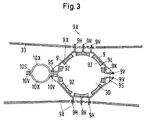
- two further clamps 9 and 10 are also detachably mounted.
- the clamp 9 is attached so that it encompasses the concrete mast 30.
- the clamp 10 is on the Clamp 9 held so that it points horizontally outwards, so that it is is located in a region between the conductor cables 33 of the two cross members 31.
- the clamp 9 consists of two components 9X, each have five edges 9K and 9L. These are arranged in a semicircle. there the second halves of the two opposing edges 9K are on the right Angle bent outwards so that they have flat extensions 9V. Two each Extensions 9V are joined together and with a screw 9S are connected.
- the inner diameter of the clamp 9 is a few centimeters larger than the outer diameter of the concrete mast 30. The between the clamp 9 and the concrete mast 30 remaining space is in some areas with 9Z hardwood components filled out.
- the areas the components 9Z, which face the concrete mast 30, are concave, so that they fit the concrete mast 30 very well.
- the components 9Z are detachably attached to the inside of the clamp 9. If necessary, they can be exchanged for wider or narrower components 9Z depending on the size of the outer diameter of the respective concrete mast 30 is.
- the clamp 10 is composed of two semicircular components 10X.
- the inside diameter the clamp 10 is adapted to the outer diameter of the stick tree 1.
- Each component 10X has a two-dimensional extension at its two ends 10V on.
- Two extensions 10V joined together are over at least one screw 10S releasably connected.
- Two extensions put together 10V are for fastening the clamp 10 to the clamp 9 between two extensions 9V arranged. You will be screwed together with these by a 9S held together.
- the clamps 9 and 10 are only installed when the stick tree 1 is positioned so that its longitudinal axis is oriented vertically and the end piece 3 points upwards, so that the steel tube 2 passes through the clamp 10 can be.
- a large roller 11 is mounted on one of the two cross members 31.
- a another roller 12 is installed at the foot of the concrete mast 30, as shown in FIG. 4.
- the assembled stick 1 is then with its flattened connector 2F rotatably attached to the clamp 7.
- a rope 13 is a double-deck winch 4 over the two rollers 12 and 11 and with the Connection piece 2F of the floor tree 1 still lying on the floor 100 is connected.
- the Floor tree 1 is pulled upwards with the rope 13 until the flat end piece 2F is located between the clamp 7 and mounted with the screw 7S can be that the cane 1 to the concrete mast 30 pivoted away from this can be.
- the rope 13 with the free end of the boom 4 connected.
- the stick tree 1 is tilted upwards so that the end piece 3 faces upwards.
- a tab 4L with an eyelet 4H is provided at the free end of the boom 4, as shown in FIG. 1, therefor a tab 4L with an eyelet 4H is provided.
- the Stick tree 1 With a second rope 15 of the double-deck winch 14, which is connected to the free end of the end piece 3, the Stick tree 1 held so far from the concrete mast 30 during erection until for the rope 13 is a sufficient angle for direct tilting into the final position of the cane 1 is reached.
- a tension-resistant line 17 (here only one shown) attached for the erection of the stick tree 1.
- the clamp 18 is is mounted at a distance of 0.30m above the clamp 9.
- the lines become 17 passed over the conductor ropes 33 to the floor 100.
- You will first when erecting used for lateral stabilization of the stick tree 1. In doing so, they are off the ground 100 made by hand by fitters. If the longitudinal axis of the stick 1 is aligned vertically, the two clamps 9 and 10 are installed as above described. The stick tree 1 is then subjected to static loads in the clamp 10 fixed. Then the second ends of the lines 17 are anchored in the floor 100.
- one of the lines 17 is previously put on a clamp 19, which is installed directly above the clamp 18. Through the two lines 17 greater safety and a lower dead weight of the stick tree 1 are achieved.
- the conductor ropes 33 are disconnected and suspended on the clamp 9. This is on the sides parallel to the wire ropes
- 33 each have three eyelets 9H, as shown in FIGS. 1, 3 and 5 are shown.
- the conductor ropes 33 are only hung about 1.0 m lower. This means that the vertical distances to objects crossing below (not here shown) still sufficient. Costs for scaffolding and / or other measures are thus avoided.
- the crossbeams 31 made of concrete, which are to be replaced, are shown in FIG. 5, suspended with a slip 20, which encompasses each cross member 31, on a fork anchor 21.
- the fork anchor 21 is attached to the roller 22 and 23 running rope 28 hooked.
- the rollers 22 and 23 are on a tab 3L of the end piece or a tab 4L of the boom 4 is arranged.
- the upper one to be cut off The end of the concrete mast 30A becomes horizontal with a pull stroke (not shown here) intercepted.
- the lines are at the ends of the trusses 31 25 and 26 attached and the concrete mast 30 according to the section line A-A 'horizontally cut off.
- the cut end 30A of the concrete mast 30 with the two cross members 31 is reduced to the vertical with the train stroke.
- the boom 4 will now with the help of lines 25 and 26 pivoted by 90 ° so that the longitudinal axes of the two trusses 31 run parallel to the conductor cables 33. Since the boom 4 a 0.80 m in length, the cut end 30A of the concrete mast 30 hangs with the trusses 31 in front of the conductor ropes 33 which are suspended from the eyelets 9H of the clamp 9 are. This allows the end 30A of the concrete mast 30 to open without difficulty the floor 100 are drained.
- FIG. 7 shows a tip 35 with which the concrete mast 30 according to FIG. 8 is now on its upper end 30A is provided.
- This is made from a commercial, galvanized Made of sheet steel. It has a cross section that consists of eight edges of equal length (here not shown) is limited.
- the tip 35 is designed so that it the concrete mast 30 encloses envelope-like over a defined length. Because concrete poles in general are not absolutely round and straight and their diameter is not measured with millimeter accuracy can be, the tip 35 is provided with a diameter of five mm is greater than that of the concrete mast 30.
- the length of the section 36 with which the tip 35 overlaps the upper end 36A is determined by the diameter of the concrete mast 30.
- the length of section 36 must be at least 0.57 m.
- the length of the tip 35 thus results from the length of the Area that is damaged on the concrete mast 30 and must therefore be replaced, plus the Length of the required overlap 36.
- the tip 35 is at its second, upward-facing end with two provided outward flanges 37 and 38.
- the height of the flanges 37 and 38 is about 0.30m. This is to be added to the length of 2.14 m, so that gives a total length of the tip 35 of about 2.44 m.
- the flanges 37 and 38 are arranged in a common plane perpendicular to the longitudinal axis of the cross member 31.
- On each flange 37, 38 is a cross member 31 made of hot-dip galvanized, coated Screwed steel sheet.
- the tip 35 is also designed so that the new trusses 31 after installing the tip 35 on the concrete mast 30 in the same Height as the original trusses 31 are arranged.
- the tip 35 is with the assembled trusses 31 and the insulator chains 32 Using the cane 1 raised in the same way as the severed end 30A of the concrete mast 30 was previously drained, so high that it was above the Concrete mast 30 hangs. With the help of lines 25 and 26, the boom 4 is back in his original position swung back. The tip 35 is shown with that in FIG Rope 27 pulled over the roller 23 to the center of the concrete mast 30 and then with the two ropes running over the rollers 12 and 12A at the foot of the concrete mast 30 27 and 28 of the double stick winch 14 lowered until the tip 35 on the clamp 9 sits on. The trusses 31 are aligned, the tip 35 is grounded and with non-shrinking fast cement (not shown here) poured out.
Landscapes
- Engineering & Computer Science (AREA)
- Architecture (AREA)
- Civil Engineering (AREA)
- Structural Engineering (AREA)
- Conveying And Assembling Of Building Elements In Situ (AREA)
- Vehicle Cleaning, Maintenance, Repair, Refitting, And Outriggers (AREA)
- Ladders (AREA)
- Paper (AREA)
- Shovels (AREA)
Abstract
Description
- Fig. 1
- einen erfindungsgemäßen Stockbaum für Beton- und Stahlvollwandmaste,
- Fig. 2
- Montagehilfen für die Erhöhung und/oder Sanierung,
- Fig. 3
- eine Doppelschelle zum Verbinden des Stockbaums mit einem Betonmast,
- Fig. 4
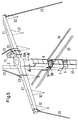
- das Hochziehen des Stockbaums an einem Betonmast,
- Fig. 5
- die Verbindung des Stockbaums mit dem oberen Ende eines Betonmasten,
- Fig. 6
- das obere Ende eines Betonmastes nach dem Abtrennen,
- Fig. 7
- eine neue Spitze für den Betonmast,
- Fig. 8
- einen Stockbaum mit der neuen Spitze, über das freie Ende des Betonmasts gestülpt ist.
Claims (10)
- Stockbaum für Beton- und Stahlvollwandmaste, gekennzeichnet, durch ein Stahlrohr (2) als Kernstück, das am ersten Ende (2A) mit einem schwenkbaren Ausleger (4) und am zweiten Ende (2B) mit einem abgeflachten Anschlußstück (2F) versehen ist.
- Stockbaum nach Anspruch 1, dadurch gekennzeichnet, daß ein haubenförmiges Endstück (3) drehbar über das erste Ende (2A) des Stahlrohrs (2) gestülpt und der daran befestigte Ausleger (4) senkrecht zur Längsachse des Stahlrohrs (1) ausgerichtet und ein stabförmiges Stützelement (5) mit dem nach außen gerichteten Ende des Auslegers (3) und dem ersten, freien Ende des Endstücks (3) verbunden ist.
- Stockbaum nach einem der Ansprüche 1 oder 2, dadurch gekennzeichnet, daß eine erste Schelle (6) für die Montage des Stockbaums (1) vorgesehen ist, deren Innendurchmesser an den Querschnitt des Beton- oder Stahlvollwandmasts (30) angepaßt mit diesem verbindbar ist, und daß an der ersten Schelle (6) eine zweite Schelle (7) gehaltert ist, an der das abgeflachte Anschlußstück (2S) des Stockbaums (1) beweglich in Richtung auf den Betonmast (30) zu oder davon weg befestigbar ist.
- Stockbaum nach einem der Ansprüche 1 bis 3, dadurch gekennzeichnet, daß eine dritte Schelle (9) zur Befestigung des Stockbaums (1) am Beton- oder Stahlvollwandmasts (30) vorgesehen ist, die aus zwei Bauelementen (9X) zusammengefügt ist, die beide fünf Kanten (9K und 9L) aufweisen, die im Halbkreis angeordnet sind, daß die zweiten Hälften der beiden einander gegenüberliegenden Kanten (9K) zur Bildung von Verlängerungen (9L) im rechten Winkel nach außen gebogen sind, daß jeweils zwei der Verlängerungen (9L) zusammengefügt und lösbar miteinander verbunden und an den Kanten (9L), die parallel zu den Leiterseilen 33 ausgerichtet sind, außen Ösen (9H) für die Halterung der Leiterseile 33 befestigt sind, und daß der Innendurchmesser der Schelle (9) einige Zentimeter größer ist als der Außendurchmesser des Beton- oder Stahlvollwandmasts (30) und der zwischen der Schelle (9) und dem Beton- oder Stahlvollwandmasts (30) verbleibende Raum bereichsweise mit Bauelementen (9Z) aus Hartholz ausgefüllt ist, deren Innenseiten konkav geformt sind.
- Stockbaum nach einem der Ansprüche 1 bis 4, dadurch gekennzeichnet, daß die Schelle 10 ist aus zwei halbkreisförmigen Bauelementen (10X) zusammengesetzt und ihr Innendurchmesser an den Außendurchmesser des Stahlrohrs (2) angepaßt ist, daß jedes Bauelement (10X) an seinen beiden Enden jeweils eine nach außen gerichtete flächige Verlängerung (10V) aufweist und zwei aneinander gefügte Verlängerungen (10V) lösbar miteinander verbunden sind, daß zwei zusammengefügte Verlängerungen (10V) zur Befestigung der Schelle (10) an der Schelle (9) zwischen zwei Verlängerungen (9V) angeordnet und zusammen mit diesen lösbar zusammengehalten sind, und daß das Stahlrohr (2) in der Schelle (10) fixierbar ist.
- Stockbaum nach einem der Ansprüche 1 bis 5, dadurch gekennzeichnet, daß das Endstück (3) mit zwei Rollen (22 und 23) versehen ist, daß ein Rolle (22) an einer Lasche (4L) am freien Ende des Auslegers (4) und die zweite Rolle (23) an einer Lasche (3L) unmittelbar am Endstück (3) angeordnet ist, und daß jeweils ein Seil (27, 28) über eine der Rollen (22, 23) geführt und mit einer Doppelstockwinde (14) verbindbar ist.
- Verfahren zur Erhöhung und/oder Sanierung eines Betonmasts oder Stahlvollwandmasts mit zwei Traversen (31), Isolatorenketten (32) und Leiterseilen (33) unter Verwendung eines Stockbaums (1) gemäß Patentanspruch 1, dadurch gekennzeichnet, daß der Stockbaum (1) am Betonmast (30) lösbar montiert, die Leiterseile (33) von den Isolatorenketten (31) entfernt und in einem geringen Abstand unterhalb der Traversen (31) am Betonmast (30) gehaltert werden, daß das an einem Ausleger (4) des Stockbaums (1) befestigte Ende (30A) des Betonmasts (30) in einem definierten Abstand unterhalb der Traversen (31) vom Betonmast (30) abgetrennt und daraufhin auf den Boden (100) abgesenkt wird, daß an dem Ausleger (4) eine aus Stahl gefertigte Spitze (35) mit zwei daran montierten und mit Isolatorenketten (32) versehene Traversen (31) befestigt, nach oben gezogen und über das Ende des Betonmasts (30) gestülpt und ausgerichtet wird, und daß die Leiterseile (33) an den Isolatorenketten (32) wieder angehängt und in Betrieb genommen werden.
- Verfahren nach Anspruch 7, dadurch gekennzeichnet, daß an dem Betonmast (30) eine Steckleiter (8) und in einem definierten Abstand unterhalb der Unterseite der Traversen (31) eine erste Schelle (6) des Stockbaums (1), sowie eine erste Rolle (11) an einer der Traversen (31) und eine zweite Rolle (12) am Fuß des Betonmasts (30) montiert wird, daß an der ersten Schelle (6) eine zweite parallel zu den Leiterseilen (33) ausgerichtet Schelle (7) befestigt und ein Seil (13) mit dem zweiten Ende (2B) des Stockbaums (1) verbunden, über die erste Rolle (11) und die zweite Rolle (12) geführt und mit einer Doppel-Stockwinde (14) verbunden wird, daß der Stockbaum (1) nach oben gezogen und mit einem am zweiten Ende (2B) vorgesehenes abgeflachtes Anschlußstück (2S) an der zweiten Schelle (7) von dem Betonmast oder Stahlvollwandmast (30) weg oder hin schwenkbar installiert wird, daß ein Seil (13) mit dem Ausleger (4) am Endstück (3) des Stockbaums (1) verbunden wird und der Stockbaum (1) senkrecht, mit dem Ausleger (4) nach oben weisend, ausgerichtet und dabei mit einem, mit dem freien Ende des Endstücks (3) verbundenen zweiten Seil (15) der Doppel-Stockwinde (14) in einem vorgebbaren Abstand vom Betonmast (30) gehalten wird, bis für das Seil (13) ein ausreichender Winkel für das direkte Ziehen bis in die endgültige Stellung des Stockbaums (1) erreicht wird.
- Verfahren nach einem der Ansprüche 7 oder 8, dadurch gekennzeichnet, daß eine dritte Schelle (9) des Stockbaums (1) einen Meter oberhalb der ersten Schelle (6) installiert und der Stockbaum (1) in der mit ihr verbundenen Schelle (10) statisch belastbar fixiert und zudem mit zwei zugfesten Seilen (17) verbunden wird, deren erste Enden in je eine unterhalb des Auslegers (4) installierte Schelle (18 und 19) eingehängt und deren zweite Enden zum Boden (100) hin abgespannt und dort verankert werden, daß die Leiterseile (33) anschließend ausgeklemmt und in Ösen (9H) der Schelle (9) gehängt werden, daß das obere Ende (30A) des Masts (30) mit den Traversen (31) am dem Ausleger (4) des Stockbaum (1) befestigt, an den Enden der Traversen (31) jeweils eine Leine (25 und 26) fixiert und der Betonmast (30) in einem definierten Abstand unterhalb der Unterseite der Traversen (31) horizontal abgeschnitten wird, daß der Ausleger (4) mit Hilfe der Leinen (25 und 26) um 90° geschwenkt und das Ende (30A) des Betonmasts (30) auf den Boden (100) abgelassen wird.
- Verfahren nach einem der Ansprüche 7 bis 9, dadurch gekennzeichnet, daß eine Spitze (35) aus Stahlblech mit zwei Traversen (31) aus Stahl und Isolatorenketten (32) vormontiert, an dem Ausleger (4) befestigt, nach oben gezogen und so gedreht wird, bis die Längsachsen der Traversen (31) senkrecht zur Richtung der Leiterseile (33) weisen, daß die Traversen (31) anschließend durch Drehen des Auslegers (4) senkrecht zu den Leiterseilen (33) ausgerichtet werden, daß die Spitze (35) mit einem zusätzlichen Seil (27) und einer Rolle (23) zu der Mitte des Betonmasts (30) gezogen und dann mit zwei Seilen (27 und 28) abgesenkt, über den Betonmast (30) gestülpt und auf die Schelle (9) aufgesetzt wird, und daß die Traversen (31) ausgerichtet, geerdet und die Spitze (35) mit schwundfreiem Schnellzement ausgegossen wird und nach dem Aushärten desselben die Leiterseile (33) an den Isolatorenketten (32) der Tavernen (31) befestigt werden.
Applications Claiming Priority (2)
| Application Number | Priority Date | Filing Date | Title |
|---|---|---|---|
| DE19946060A DE19946060A1 (de) | 1999-09-25 | 1999-09-25 | Verfahren und Vorrichtung zur Erhöhung und/oder Sanierung von Masten |
| DE19946060 | 1999-09-25 |
Publications (3)
| Publication Number | Publication Date |
|---|---|
| EP1087077A1 true EP1087077A1 (de) | 2001-03-28 |
| EP1087077B1 EP1087077B1 (de) | 2005-07-27 |
| EP1087077B8 EP1087077B8 (de) | 2005-09-28 |
Family
ID=7923328
Family Applications (1)
| Application Number | Title | Priority Date | Filing Date |
|---|---|---|---|
| EP00119145A Expired - Lifetime EP1087077B8 (de) | 1999-09-25 | 2000-09-05 | Verfahren und Vorrichtung zur Erhöhung und/oder Sanierung von Masten |
Country Status (3)
| Country | Link |
|---|---|
| EP (1) | EP1087077B8 (de) |
| AT (1) | ATE300644T1 (de) |
| DE (2) | DE19946060A1 (de) |
Cited By (4)
| Publication number | Priority date | Publication date | Assignee | Title |
|---|---|---|---|---|
| CN101649684B (zh) * | 2009-09-14 | 2011-01-05 | 常州第一建筑工程有限公司 | 屋顶桅杆的安装方法 |
| CN103912135A (zh) * | 2014-04-04 | 2014-07-09 | 山东省产品质量检验研究院 | 网架结构弦杆矫正装置及矫正方法 |
| CN112627623A (zh) * | 2020-12-03 | 2021-04-09 | 国网辽宁省电力有限公司锦州供电公司 | 带电更换电线杆方法 |
| CN113236011A (zh) * | 2021-06-03 | 2021-08-10 | 河北久金电力器材制造有限公司 | 便于安装的横担及使横担便于安装的方法 |
Families Citing this family (3)
| Publication number | Priority date | Publication date | Assignee | Title |
|---|---|---|---|---|
| CN110805353A (zh) * | 2019-09-29 | 2020-02-18 | 国网江苏省电力有限公司徐州供电分公司 | 一种利用组合式电动抱杆架设输电塔架的方法 |
| CN112813855B (zh) * | 2021-01-22 | 2025-03-25 | 广州珠江黄埔大桥建设有限公司 | 钢箱梁斜腹杆开裂病害的阻尼式弹性支撑处置方法 |
| CN113833300B (zh) * | 2021-09-17 | 2023-01-20 | 广东电网有限责任公司 | 一种输电塔维修方法 |
Citations (5)
| Publication number | Priority date | Publication date | Assignee | Title |
|---|---|---|---|---|
| GB350465A (en) * | 1930-02-05 | 1931-06-05 | Eugen Haber | Improvements in staging for use in building metal chimneys in sections |
| DE1198981B (de) * | 1964-03-06 | 1965-08-19 | Bbc Brown Boveri & Cie | Montagegeraet fuer Rohrantennenelemente und Mastbauwerke |
| FR2058857A5 (de) * | 1969-09-30 | 1971-05-28 | Morihain Marcel | |
| DE2255713A1 (de) * | 1972-11-14 | 1974-05-16 | Starkstrom Anlagen Gmbh | Bauelementensatz fuer die errichtung von masten |
| DE19915499A1 (de) | 1999-04-07 | 2000-10-12 | Abb Patent Gmbh | Betonmast für Freileitungen |
Family Cites Families (6)
| Publication number | Priority date | Publication date | Assignee | Title |
|---|---|---|---|---|
| DE552097C (de) * | 1927-04-02 | 1932-06-09 | Eugen Haber | Verfahren und Vorrichtung zum Auffuehren von Blechschornsteinen |
| US3074564A (en) * | 1961-03-01 | 1963-01-22 | Chicago Bridge & Iron Co | Mast extension jib |
| DE1658882A1 (de) * | 1967-08-18 | 1971-02-11 | Inst Stahlbeton | Verbindungsmittel fuer Stahlbetonteile,insbesondere fuer Stahlbetonmaste |
| DE3506677A1 (de) * | 1985-02-26 | 1986-08-28 | Ludwig Freytag GmbH & Co KG, 2900 Oldenburg | Verfahren zum verstaerken von freileitungsmasten aus beton |
| DE3608771A1 (de) * | 1986-03-15 | 1987-09-24 | Bbc Brown Boveri & Cie | Innenstockbaum |
| JP2879316B2 (ja) * | 1995-07-14 | 1999-04-05 | 株式会社藤栄建設興業 | 建柱用ポール |
-
1999
- 1999-09-25 DE DE19946060A patent/DE19946060A1/de not_active Ceased
-
2000
- 2000-09-05 EP EP00119145A patent/EP1087077B8/de not_active Expired - Lifetime
- 2000-09-05 AT AT00119145T patent/ATE300644T1/de not_active IP Right Cessation
- 2000-09-05 DE DE50010815T patent/DE50010815D1/de not_active Expired - Lifetime
Patent Citations (5)
| Publication number | Priority date | Publication date | Assignee | Title |
|---|---|---|---|---|
| GB350465A (en) * | 1930-02-05 | 1931-06-05 | Eugen Haber | Improvements in staging for use in building metal chimneys in sections |
| DE1198981B (de) * | 1964-03-06 | 1965-08-19 | Bbc Brown Boveri & Cie | Montagegeraet fuer Rohrantennenelemente und Mastbauwerke |
| FR2058857A5 (de) * | 1969-09-30 | 1971-05-28 | Morihain Marcel | |
| DE2255713A1 (de) * | 1972-11-14 | 1974-05-16 | Starkstrom Anlagen Gmbh | Bauelementensatz fuer die errichtung von masten |
| DE19915499A1 (de) | 1999-04-07 | 2000-10-12 | Abb Patent Gmbh | Betonmast für Freileitungen |
Cited By (4)
| Publication number | Priority date | Publication date | Assignee | Title |
|---|---|---|---|---|
| CN101649684B (zh) * | 2009-09-14 | 2011-01-05 | 常州第一建筑工程有限公司 | 屋顶桅杆的安装方法 |
| CN103912135A (zh) * | 2014-04-04 | 2014-07-09 | 山东省产品质量检验研究院 | 网架结构弦杆矫正装置及矫正方法 |
| CN112627623A (zh) * | 2020-12-03 | 2021-04-09 | 国网辽宁省电力有限公司锦州供电公司 | 带电更换电线杆方法 |
| CN113236011A (zh) * | 2021-06-03 | 2021-08-10 | 河北久金电力器材制造有限公司 | 便于安装的横担及使横担便于安装的方法 |
Also Published As
| Publication number | Publication date |
|---|---|
| DE19946060A1 (de) | 2001-04-26 |
| EP1087077B8 (de) | 2005-09-28 |
| DE50010815D1 (de) | 2005-09-01 |
| EP1087077B1 (de) | 2005-07-27 |
| ATE300644T1 (de) | 2005-08-15 |
Similar Documents
| Publication | Publication Date | Title |
|---|---|---|
| DE69214392T2 (de) | Schnellkupplungsvorrichtung für Auslegerteile von Kränen und dgl. | |
| CH656408A5 (de) | Haengebruecke. | |
| DE1434325A1 (de) | Schalungshaut fuer eine Kletterschaltung und Verfahren zur Herstellung turmartiger Bauwerke aus Beton | |
| EP3896240A1 (de) | Baugerüst | |
| EP4334230B1 (de) | Topmodul und verfahren zum abschliessen eines aufzugschachts einer aufzuganlage | |
| DE1653766B1 (de) | Vorrichtung zum Anschliessen und Wiederl¦sen einer Pumpe in einem Brunnenschacht | |
| EP1087077A1 (de) | Verfahren und Vorrichtung zur Erhöhung und/oder Sanierung von Masten | |
| EP2687632A1 (de) | Vorrichtung und Montagebrücke zur Abhängung eines Bauteils | |
| DE2361133A1 (de) | Geruestkran | |
| DE4114531C2 (de) | Arbeitsbühne für Wände oder Schalungen | |
| DE2713485C3 (de) | Freileitungs-Fahrwagen | |
| DE3608771C2 (de) | ||
| EP0161634A2 (de) | Spreize, insbesondere zur Verwendung bei Verbauen, z. B. Grabenverbau | |
| EP1043457B1 (de) | Betonmast für Freileitungen | |
| DE3242570A1 (de) | Arbeitsgeruest | |
| DE2517227B1 (de) | Vorrichtung zur montage von vorhangwaenden | |
| DE4430761A1 (de) | Verfahren und Vorrichtung zum Auswechseln eines Mastkopfes eines Tragmastes einer Hochspannungsfreileitung | |
| EP3754134A1 (de) | Spannvorrichtung für eine eckverschalung | |
| EP0320855A2 (de) | Abbruchanlage für Schornsteine vor allem Konvergente | |
| EP1247925A2 (de) | Vorrichtung zum Erhöhen von Hochspannungsfreileitungsmasten | |
| DE3048043A1 (de) | Schalungsstuetze | |
| EP0027576B1 (de) | Abstützeinrichtung als Zwischenstück bei einer Grabenverbauvorrichtung | |
| WO1985002879A1 (fr) | Dispositif porteur pour echafaudage | |
| DE3007691C2 (de) | ||
| EP0390965A1 (de) | Befestigungsvorrichtung |
Legal Events
| Date | Code | Title | Description |
|---|---|---|---|
| PUAI | Public reference made under article 153(3) epc to a published international application that has entered the european phase |
Free format text: ORIGINAL CODE: 0009012 |
|
| AK | Designated contracting states |
Kind code of ref document: A1 Designated state(s): AT BE CH CY DE DK ES FI FR GB GR IE IT LI LU MC NL PT SE |
|
| AX | Request for extension of the european patent |
Free format text: AL PAYMENT 20000919;LT PAYMENT 20000919;LV PAYMENT 20000919;MK PAYMENT 20000919;RO PAYMENT 20000919;SI PAYMENT 20000919 |
|
| 17P | Request for examination filed |
Effective date: 20010508 |
|
| RAP1 | Party data changed (applicant data changed or rights of an application transferred) |
Owner name: ABB PATENT GMBH |
|
| AKX | Designation fees paid |
Free format text: AT BE CH CY DE DK ES FI FR GB GR IE IT LI LU MC NL PT SE |
|
| AXX | Extension fees paid |
Free format text: AL PAYMENT 20000919;LT PAYMENT 20000919;LV PAYMENT 20000919;MK PAYMENT 20000919;RO PAYMENT 20000919;SI PAYMENT 20000919 |
|
| 17Q | First examination report despatched |
Effective date: 20030929 |
|
| GRAP | Despatch of communication of intention to grant a patent |
Free format text: ORIGINAL CODE: EPIDOSNIGR1 |
|
| GRAS | Grant fee paid |
Free format text: ORIGINAL CODE: EPIDOSNIGR3 |
|
| GRAA | (expected) grant |
Free format text: ORIGINAL CODE: 0009210 |
|
| AK | Designated contracting states |
Kind code of ref document: B1 Designated state(s): AT BE CH CY DE DK ES FI FR GB GR IE IT LI LU MC NL PT SE |
|
| AX | Request for extension of the european patent |
Extension state: AL LT LV MK RO SI |
|
| PG25 | Lapsed in a contracting state [announced via postgrant information from national office to epo] |
Ref country code: IE Free format text: LAPSE BECAUSE OF FAILURE TO SUBMIT A TRANSLATION OF THE DESCRIPTION OR TO PAY THE FEE WITHIN THE PRESCRIBED TIME-LIMIT Effective date: 20050727 Ref country code: IT Free format text: LAPSE BECAUSE OF FAILURE TO SUBMIT A TRANSLATION OF THE DESCRIPTION OR TO PAY THE FEE WITHIN THE PRESCRIBED TIME-LIMIT;WARNING: LAPSES OF ITALIAN PATENTS WITH EFFECTIVE DATE BEFORE 2007 MAY HAVE OCCURRED AT ANY TIME BEFORE 2007. THE CORRECT EFFECTIVE DATE MAY BE DIFFERENT FROM THE ONE RECORDED. Effective date: 20050727 Ref country code: NL Free format text: LAPSE BECAUSE OF FAILURE TO SUBMIT A TRANSLATION OF THE DESCRIPTION OR TO PAY THE FEE WITHIN THE PRESCRIBED TIME-LIMIT Effective date: 20050727 Ref country code: GB Free format text: LAPSE BECAUSE OF FAILURE TO SUBMIT A TRANSLATION OF THE DESCRIPTION OR TO PAY THE FEE WITHIN THE PRESCRIBED TIME-LIMIT Effective date: 20050727 Ref country code: FI Free format text: LAPSE BECAUSE OF FAILURE TO SUBMIT A TRANSLATION OF THE DESCRIPTION OR TO PAY THE FEE WITHIN THE PRESCRIBED TIME-LIMIT Effective date: 20050727 |
|
| REG | Reference to a national code |
Ref country code: GB Ref legal event code: FG4D Free format text: NOT ENGLISH |
|
| REG | Reference to a national code |
Ref country code: CH Ref legal event code: EP |
|
| REG | Reference to a national code |
Ref country code: IE Ref legal event code: FG4D Free format text: LANGUAGE OF EP DOCUMENT: GERMAN |
|
| REF | Corresponds to: |
Ref document number: 50010815 Country of ref document: DE Date of ref document: 20050901 Kind code of ref document: P |
|
| PG25 | Lapsed in a contracting state [announced via postgrant information from national office to epo] |
Ref country code: CY Free format text: LAPSE BECAUSE OF FAILURE TO SUBMIT A TRANSLATION OF THE DESCRIPTION OR TO PAY THE FEE WITHIN THE PRESCRIBED TIME-LIMIT Effective date: 20050905 Ref country code: AT Free format text: LAPSE BECAUSE OF NON-PAYMENT OF DUE FEES Effective date: 20050905 |
|
| RAP2 | Party data changed (patent owner data changed or rights of a patent transferred) |
Owner name: ABB LEITUNGSBAU GMBH |
|
| PG25 | Lapsed in a contracting state [announced via postgrant information from national office to epo] |
Ref country code: BE Free format text: LAPSE BECAUSE OF NON-PAYMENT OF DUE FEES Effective date: 20050930 Ref country code: MC Free format text: LAPSE BECAUSE OF NON-PAYMENT OF DUE FEES Effective date: 20050930 Ref country code: LU Free format text: LAPSE BECAUSE OF NON-PAYMENT OF DUE FEES Effective date: 20050930 Ref country code: LI Free format text: LAPSE BECAUSE OF NON-PAYMENT OF DUE FEES Effective date: 20050930 Ref country code: CH Free format text: LAPSE BECAUSE OF NON-PAYMENT OF DUE FEES Effective date: 20050930 |
|
| PG25 | Lapsed in a contracting state [announced via postgrant information from national office to epo] |
Ref country code: GR Free format text: LAPSE BECAUSE OF FAILURE TO SUBMIT A TRANSLATION OF THE DESCRIPTION OR TO PAY THE FEE WITHIN THE PRESCRIBED TIME-LIMIT Effective date: 20051027 Ref country code: DK Free format text: LAPSE BECAUSE OF FAILURE TO SUBMIT A TRANSLATION OF THE DESCRIPTION OR TO PAY THE FEE WITHIN THE PRESCRIBED TIME-LIMIT Effective date: 20051027 Ref country code: SE Free format text: LAPSE BECAUSE OF FAILURE TO SUBMIT A TRANSLATION OF THE DESCRIPTION OR TO PAY THE FEE WITHIN THE PRESCRIBED TIME-LIMIT Effective date: 20051027 |
|
| NLT2 | Nl: modifications (of names), taken from the european patent patent bulletin |
Owner name: ABB LEITUNGSBAU GMBH Effective date: 20050907 |
|
| PG25 | Lapsed in a contracting state [announced via postgrant information from national office to epo] |
Ref country code: ES Free format text: LAPSE BECAUSE OF FAILURE TO SUBMIT A TRANSLATION OF THE DESCRIPTION OR TO PAY THE FEE WITHIN THE PRESCRIBED TIME-LIMIT Effective date: 20051107 |
|
| PG25 | Lapsed in a contracting state [announced via postgrant information from national office to epo] |
Ref country code: PT Free format text: LAPSE BECAUSE OF FAILURE TO SUBMIT A TRANSLATION OF THE DESCRIPTION OR TO PAY THE FEE WITHIN THE PRESCRIBED TIME-LIMIT Effective date: 20051227 |
|
| LTIE | Lt: invalidation of european patent or patent extension |
Effective date: 20050727 |
|
| NLV1 | Nl: lapsed or annulled due to failure to fulfill the requirements of art. 29p and 29m of the patents act | ||
| GBV | Gb: ep patent (uk) treated as always having been void in accordance with gb section 77(7)/1977 [no translation filed] |
Effective date: 20050727 |
|
| REG | Reference to a national code |
Ref country code: IE Ref legal event code: FD4D |
|
| REG | Reference to a national code |
Ref country code: CH Ref legal event code: PL |
|
| PLBE | No opposition filed within time limit |
Free format text: ORIGINAL CODE: 0009261 |
|
| STAA | Information on the status of an ep patent application or granted ep patent |
Free format text: STATUS: NO OPPOSITION FILED WITHIN TIME LIMIT |
|
| 26N | No opposition filed |
Effective date: 20060428 |
|
| EN | Fr: translation not filed | ||
| PG25 | Lapsed in a contracting state [announced via postgrant information from national office to epo] |
Ref country code: FR Free format text: LAPSE BECAUSE OF FAILURE TO SUBMIT A TRANSLATION OF THE DESCRIPTION OR TO PAY THE FEE WITHIN THE PRESCRIBED TIME-LIMIT Effective date: 20060922 |
|
| BERE | Be: lapsed |
Owner name: ABB PATENT G.M.B.H. Effective date: 20050930 |
|
| PG25 | Lapsed in a contracting state [announced via postgrant information from national office to epo] |
Ref country code: FR Free format text: LAPSE BECAUSE OF FAILURE TO SUBMIT A TRANSLATION OF THE DESCRIPTION OR TO PAY THE FEE WITHIN THE PRESCRIBED TIME-LIMIT Effective date: 20050930 |
|
| PG25 | Lapsed in a contracting state [announced via postgrant information from national office to epo] |
Ref country code: FR Free format text: LAPSE BECAUSE OF FAILURE TO SUBMIT A TRANSLATION OF THE DESCRIPTION OR TO PAY THE FEE WITHIN THE PRESCRIBED TIME-LIMIT Effective date: 20050727 |
|
| PGFP | Annual fee paid to national office [announced via postgrant information from national office to epo] |
Ref country code: DE Payment date: 20120921 Year of fee payment: 13 |
|
| REG | Reference to a national code |
Ref country code: DE Ref legal event code: R119 Ref document number: 50010815 Country of ref document: DE Effective date: 20140401 |
|
| PG25 | Lapsed in a contracting state [announced via postgrant information from national office to epo] |
Ref country code: DE Free format text: LAPSE BECAUSE OF NON-PAYMENT OF DUE FEES Effective date: 20140401 |