EP1076784B1 - Chaine de guidage d'elements de transport d'energie - Google Patents
Chaine de guidage d'elements de transport d'energie Download PDFInfo
- Publication number
- EP1076784B1 EP1076784B1 EP99932627A EP99932627A EP1076784B1 EP 1076784 B1 EP1076784 B1 EP 1076784B1 EP 99932627 A EP99932627 A EP 99932627A EP 99932627 A EP99932627 A EP 99932627A EP 1076784 B1 EP1076784 B1 EP 1076784B1
- Authority
- EP
- European Patent Office
- Prior art keywords
- chain
- rollers
- energy guiding
- energy
- straps
- Prior art date
- Legal status (The legal status is an assumption and is not a legal conclusion. Google has not performed a legal analysis and makes no representation as to the accuracy of the status listed.)
- Expired - Lifetime
Links
Images


Classifications
-
- F—MECHANICAL ENGINEERING; LIGHTING; HEATING; WEAPONS; BLASTING
- F16—ENGINEERING ELEMENTS AND UNITS; GENERAL MEASURES FOR PRODUCING AND MAINTAINING EFFECTIVE FUNCTIONING OF MACHINES OR INSTALLATIONS; THERMAL INSULATION IN GENERAL
- F16G—BELTS, CABLES, OR ROPES, PREDOMINANTLY USED FOR DRIVING PURPOSES; CHAINS; FITTINGS PREDOMINANTLY USED THEREFOR
- F16G13/00—Chains
- F16G13/12—Hauling- or hoisting-chains so called ornamental chains
- F16G13/16—Hauling- or hoisting-chains so called ornamental chains with arrangements for holding electric cables, hoses, or the like
-
- H—ELECTRICITY
- H02—GENERATION; CONVERSION OR DISTRIBUTION OF ELECTRIC POWER
- H02G—INSTALLATION OF ELECTRIC CABLES OR LINES, OR OF COMBINED OPTICAL AND ELECTRIC CABLES OR LINES
- H02G11/00—Arrangements of electric cables or lines between relatively-movable parts
- H02G11/006—Arrangements of electric cables or lines between relatively-movable parts using extensible carrier for the cable, e.g. self-coiling spring
Definitions
- the invention relates to an energy guiding chain for guidance of cables, hoses or the like with a number of hinged interconnected chain links through each other formed parallel tabs and connecting transverse webs be, with the energy chain so traversable is that this is an upper strand, a lower strand and a this connecting deflection, wherein the upper strand on the Untertrum rests, and being at least on some links of upper run and / or lower run casters are provided, which are arranged so that they are on provided the chain links of the opposite strands Running surfaces unrolled during a movement of the energy chain are.
- Such cable drag chains have certain applications a considerable length in the range of 100 meters or more. For the passage of the Energy supply chain are thus correspondingly high drive power the travel drive necessary. This particular if the upper strand of the energy chain on the lower strand is handled lying, as this is a corresponding Sliding friction has to be overcome in the case of very long energy chains takes on considerable values. Due to friction between Obertrum and Untertrum are subject to the respective Sliding surfaces of the chain links increased wear.
- an energy guiding chain is known, at which individual chain links assigned a support surface which is oriented so that they are together with the other support surfaces forms a plane.
- the support surfaces are provided here on the inner loop side.
- support wheels are provided, the with their peripheral surfaces on the adjacent support surface protrude, passing through a recess of the support surface passed through. This will be an energy chain created in which the supporting forces on the chain links can be derived in a favorable meadow, so that the chain links built lighter and transferred higher support forces can be.
- the object of the present invention is to provide an energy guiding chain to create, at which the upper strand on the lower strand lying with the least possible effort and Low wear is movable and the simplest possible is constructed, and in the case of long energy chains a structurally simple management of the energy chain given is.
- the object is achieved in that the Sliding rollers have a guide profile, which by several circumferential, spaced apart in the tread of the Casters arranged guide grooves is formed.
- the inventive design of the rollers can the Running characteristics further improved and noise emissions be reduced even more, as well as the friction between Untertrum and Obertrum be further reduced. simultaneously will be a safe guide for the energy chain provided.
- the guide grooves have an approximately trapezoidal Cross-sectional profile, thereby ensuring the correct alignment the rollers is guaranteed to each other.
- treads e.g. to the side outwardly projecting portions provided on the link plates be.
- rollers can directly on the link plates be secured by means of appropriate bearings, causing the holder the casters is stable according to executable. Separate connectors are not required.
- the rollers are in at the link plates arranged recesses arranged, wherein the rollers at least slightly over the link plates towards the opposite strand protrude.
- the axis of rotation of Casters are located within the cross section the link plates.
- the running surfaces for the rollers can directly through the opposite strand facing narrow sides of the Chain straps are formed.
- This can be the link plates be formed so that when stretched Energy supply chain results in a continuous tread, so that in particular in the joint areas of the link plates there are no or only minimal level differences of the tread.
- the recesses for receiving the rollers in the link plates can in the lateral direction of the link plates, i.e. transverse to the longitudinal direction of the energy chain, closed be executed.
- the width of the rollers is as large as possible choose. If necessary, the chain straps in the Area of sliding rollers with thick areas corresponding Starch be executed, the wall thickness of the link plates towards the joint areas or in the direction can decrease towards the central longitudinal axis of the link plates.
- At the link plates can be assigned to each narrow side respectively one or two or more rollers provided be, with respect to the longitudinal direction of the energy chain spaced from each other, whereby the stress of the Sliding rollers and the bearing each on several rollers can be distributed.
- the tabs can by one, possibly centered on the link plate or centrally between the two or more rollers be connected crosspiece connected.
- the Narrow sides of opposite flaps with two transverse webs in particular each immediately adjacent to the Joint or end portions may be arranged on the side flaps can, whereby the stability of the chain links especially at long links is increased.
- the tabs can be so total by four, but possibly only by three or two transverse webs be connected. Particularly advantageous, the transverse webs lateral extensions on the inside of the adjacent Cover flap partially.
- the rolling members can so with twice the number of conventional lid and floor elements the previously used members are fitted to to form a closed channel without special parts necessary.
- each link plate in each case at least one sliding roller be provided, which in the middle region of the link plate is arranged, in Lengthwise of the energy chain in front of or behind the roller, preferably in front of and behind the same, transverse webs are arranged.
- transverse webs are particularly advantageous if the link plates due to the arranged on these rollers a larger Have length.
- the treads may have chamfers which are to Sliding rollers increase in each case. This can be done by the Chain straps projecting height of the casters at a given Arrangement of the axis of rotation can be reduced, resulting in the smoothness of the energy chain has an advantageous effect.
- rollers For attachment of the rollers in the recesses of Chain straps can be provided with flanges that have a storage area for the casters, the flanges With respect to the axis of rotation of the rollers larger areas may have radial expansion, with means for Attachment of the flanges an.den link plates are provided.
- the rollers can on one side or both sides of the Flanges be stored, the rotation axis can also be on one side at the flange and at the opposite area of the link plate be stored.
- Chain links also be provided usual chain links.
- the Energy supply chain can thus essentially from previously known Chain links are constructed between which z. B. at intervals of several chain links in addition with rollers provided chain links are arranged.
- the link plates can alternatively or additionally so be formed so that these at one of the parallel to the longitudinal direction the chain running narrow side with recesses are provided for receiving casters, with the opposite Narrow side of the link plate no recesses and wherein the link plates are formed so that you choose one of the narrow sides opposite Trum facing can be mounted.
- the same link plate can thus either with mounting with or without sliding roller be used.
- the link plate is only to 180 ° about its longitudinal axis or about the axis to rotate, which in the median plane of the link plates perpendicular to their Extends longitudinally.
- the castered links have a larger one Length, d. H. a greater pitch than the conventional chain links. Exceeding a certain graduation is not really desirable, as this is a non-circular Run the chain is generated in the deflection radius, especially if Links with too different lengths alternate consecutive. According to one embodiment of the invention is therefore intended that the rollers laterally are arranged outside on the chain straps and that as treads laterally outwardly projecting widenings the link plates are provided. This can be at Chain links with casters the division of chain links to be maintained without casters.
- the energy chain at least all link plates of a strand, both outer flaps and inner flaps, with one Running surface forming broadening provided so that over the Length of the energy guiding chain at least one substantially closed tread arises.
- the rollers can each have a window-like recess penetrate in the treads forming widening.
- rollers can also unevenly over the Length of the energy chain be distributed. So can bigger ones Identity periods of Gleitrollenver whatsoever provided be, wherein the distance between the rollers to each other, for. alternate can, so that starting from a chain link in the chain longitudinal direction Sliding rollers after three, then after five, then after three etc. chain links are arranged. The distribution of Casters over the chain links can also be statistically respectively.
- both link plates same Chain link to be provided with rollers, so that the Distribution of casters on the different strands of Chain straps do not have to be symmetrical.
- An uneven or asymmetrical distribution of the rollers has the advantage that at certain times the Running the energy chain not all casters at the same time come into contact with each other, but Rather, only a few of them, with the temporal Distances between the contacts of the rollers vary can. As a result, the low impact movements in Clash of rollers unevenly over the Energy distribution chain distributed so that in a fast The same goes through the entire energy supply chain extending jerky movements are avoided. The smoothness The energy supply chain can be improved thereby.
- the Chain straps should be provided with rollers, which respect the longitudinal axis of the link plates on one side, on the opposite side or on both sides of the link plates protrude.
- These link plates can hereby optionally mounted in the area of the upper run or the lower run or if the energy chain around the termination point can be moved on both sides, on both sides of the link plates.
- the arrangement of casters is especially in energy chains possible, the more than two parallel strands chain links, with rollers on at least two strands are provided.
- the rollers can, for example exclusively on the outer strands be arranged, they can alternatively or additionally also one or more of the inner strands of the link plates be provided.
- the sections in which the through the one or more non-stretchable elements connected chain links are arranged, several chain links.
- the sections can be of equal or different length. Prefers Different lengths are used, with the sections being different down to the driver, as the tensile stress the chain increases towards the driver.
- non-stretchable elements This may be one of the cables routed in the chain act.
- the or separately The elements arranged inside the cables can be inside the chain be provided and have, for example steel cables. It However, every other has these properties Element into consideration.
- the neighboring ones arranged at the end of individual sections Chain links are preferably below each other and that to Driver nearest these links with the driver by at least one in the longitudinal direction of the chain non-stretchable and pliable in angling direction of the chain Element connected stable to tensile stress.
- the or nonextensible elements on separately arranged to the transverse webs strips, with the opposite links of the chain links are connected, attached stable.
- the lines routed through the chain are advantageously attached to these strips by means of clamping blocks, the also fasteners for the ends of steel cables or may have other corresponding elements.
- the strips can at their lying in the transverse direction of the chain End pins have the function of the pivot pin take over the relevant chain links. That means that the Pins of the strips form fit by two zueinaner aligned Openings in the overlapping areas immediately adjacent Chain links grip and thus the pivot axes form this chain links.
- This training allows one to the swivel axes oscillating arrangement of the bars attached lines and separate non-stretchable elements.
- the strips can at their lying in the transverse direction of the chain Ends have projections which formed in accordance with Grooves on the inner sides of the chain links between engage the joint areas.
- a chain series provided grooves can also be used for attachment serve other parts between the link plates.
- the energy guiding chains according to the invention can both by inner and outer plates as well as by cranked chain links being constructed.
- the transverse webs can each be detachable or be integrally attached to the side flaps or a Take width, so that a closed channel is formed.
- the Articulated connections can be made in any way and e.g. also as film hinges or the like ..
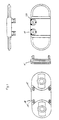
- the link plate 1 shown in Figure 1 is as an outer flap executed, with an inner flap 2 of Figure 2 for the formation a strand is hinged.
- an inner flap 2 of Figure 2 for the formation a strand is hinged.
- the tabs 1,2 are each symmetrical to the perpendicular to Longitudinal axis of the tabs median plane.
- the central regions 11, 12 of the link plates 1, 2 are as Dickstellen Kunststoffe executed and go to the inside of the chain opposite side of the tabs 1,2 on the vertical to the Lekssache the flaps extending bevels 13,14 in the End regions 3,4 over.
- a sliding roller 15 in a circular segment-shaped recess 15 a means a flange 16 rotatably fasten.
- the axis of rotation 17 of Sliding roller is at one end of the flange 16 and on the opposite end of the link plate in a recess supported.
- the sliding roller 15 can over the protruding portion 18 on one arranged on the chain links of the opposite strand Roll off the tread so that the upper strand on the Untertrum is lying on movable.
- the tread or side surface 19 is longitudinal the energy guiding chain extending, the sliding roller 15th upstream and downstream bevels 20, which are to the Slide rollers 15 rise toward and essentially on each Height of the pivot axes of the tabs begin.
- the slope the ramps 20 is comparatively low and can e.g. a height of about 3 mm over a length of 80 mm overcome. Over the vertex of the ramp 20 projects while the area 18 of the sliding roller 15 again by about 2 mm out.
- the inner plates as well as those not provided with casters Narrow sides of the outer straps have in the illustrated embodiments no chamfers on.
- the diameter of the rollers 15 corresponds in the one shown Embodiment substantially half the height of the link plate 1.
- the ramp angle on the Geitrollen (angle between the peripheral surface of the sliding roller and the ramp This is comparatively low. It can, however, too Casters compared with a significantly reduced diameter be used with the height of the link plates.
- a Chain link also two (or possibly more) sliding rollers in a row be arranged.
- the casters are also in here Thick spot area attached by means of flanges.
- the crossbars 22 are as in the link plates of FIG. 1 and 2 to the End areas of the thick areas arranged, they can possibly also be provided between the rollers.
- the tread area between the rollers 15 is parallel to the opposite narrow side of the tab.
- rollers 15 By attaching the rollers 15 by means of the flanges 11 directly on the link plates gives a special stable storage of casters.
- the casters are in the Cross-sectional contour of the energy chain and the axes of rotation arranged within the cross-sectional contour of the link plates, so that outwardly projecting areas are avoided.
- transverse webs 22 are on inner and outer plates two transverse webs 22 immediately adjacent to the end regions 3.4 arranged.
- the transverse webs 22 on the outer plates 1 overlap with their end extensions 36 the End portions 4 of the inner plates inside with only a small Game, so that by this overlap the stability of the chain is increased.
- Figure 6 shows, not required, on each link plate the energy chain 27 rollers to provide these rather, they can also be spaced apart, e.g. after every third or fourth link) arranged on the link plates be.
- the rollers arranged at a small distance, e.g. on each chain link so do the transition from the deflection 30 to the upper strand 28, the rollers first with the lower run 29 in contact and a sliding friction is avoided.
- chain links can with Rolls 38 may be provided, which have a greater length, as chain links without rollers 37 ( Figure 6).
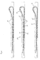
- the energy chain with a non-stretchable in the longitudinal direction of the chain and equipped in bending direction of the chain flexible steel cable be as this figure 10 can be seen.
- FIG. 10 shows an energy guiding chain 27 for receiving and guiding lines 31 between a fixed base 32 and a movable cam 33 with two parallel plate strands of transversely opposite Tabs 1, by (not shown in Fig. 10) Crossbars are interconnected.
- the immediately adjacent Tabs 1a and 1b of each tab string are in the Bending direction of the chain against each other pivotable.
- the Bending area extends into the lower strand of the chain, non-stretchable and bendable in the bending direction of the chain Elements 34 (in particular 34a, 34b, 34c, 34d, 34e, 34f and 34g) arranged. These elements connect chain links 35a, 35b, 35c, 35d, 35e, 35f and 35g with each other, the sections at a distance of several chain links from each other and from Driver 33 arranged in the relevant area of the chain are. The closest to the driver 33 chain link 35a is through the non-stretchable element 34a with the driver 33rd connected.
- FIG. 11 shows a second exemplary embodiment of the invention Energy supply chain shown.
- the rollers 15 are not covered.
- treads serve laterally both on the outer plates 1 and formed on the inner plates 2, in cross-section L-shaped Spacers 39, which are provided on the rollers 15 with Chain links 38 have window-like recesses, the are penetrated in each case by the sliding roller 15.
- the order the rollers 15 on the outer sides of the link plates 1, 2nd outside the chain cross-section has the advantage that the division the chain links 38 are selected smaller with rollers can, d. H. as small as the pitch of the chain links 37 without roles.
- rollers 15 are there only hinted shown ball bearings 25, respectively on one on the outside of the relevant link plate 1 integrally formed bearing pin 41 by means of a snap ring 42 are secured.
- FIGs 13 and 14 are two different traversing positions the energy chain, d. H. two different ones Positions each of the chain links 38 with rollers to each other.
- the chain links 38 are with rollers shown laterally offset from one another. Meet the casters 15 of the upper run 28 and the lower run 29 on each other, As shown in Figure 13, so must the upper strand Lift 28 with respect to the lower run 29, since the upper strand in the 28th illustrated sliding roller 15 on the ramp 20 and the Slide roller 15 in Untertrum 29 so to speak must climb away.
- the supernatant of the rollers 15 minimized over the running surfaces of the spacers 39, so that the rollers 15 do not skip jerkily, which would lead to unrest of the energy chain.
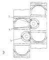
- Figures 15 to 18 show a particularly advantageous Embodiment of the energy supply chain according to the invention, in which the rollers 15 with a guide profile are provided, d. H. each several circumferential, at a distance guide grooves 40 arranged one from another with a trapezoidal shape Have cross-sectional profile.
- Cross section of the guide grooves a lateral Offsetting Obertrum 28 and Untertrum 29 entails, as this is shown in FIG.
- the offset corresponds to about the width of a guide groove 40, so that the rollers of the upper strand 28 and the lower strand 29 penetrate.
- the depth of the guide grooves 40 of course greater than or equal to the distance between the rollers 15 of the be formed by the widenings 39 treads.
- the elasticity of the energy chain allows without further ado such an offset from the upper strand 28 to the lower strand 29 via a greater length, so minimal in this way Friction resistances are ensured.
- Both the link plates and the casters exist preferably made of plastic. However, there are other combinations of materials possible, so can the link plates and / or the casters also consist of metallic materials.
Claims (20)
- Chaíne d'amenée d'énergie pour le guidage de tuyaux, de câbles ou similaires, comprenant un certain nombre de maillons de chaíne (35) reliés les uns aux autres de façon articulée, qui sont formés par des ailes (1, 2) mutuellement parallèles par des barrettes transversales (22) qui les relient, ladite chaíne d'amenée d'énergie étant capable de circuler de telle manière qu'elle forme un brin supérieur '(28), un brin inférieur (29) et une zone de renvoi (30) qui relie ceux-ci, le brin supérieur (28) reposant sur le brin inférieur (29), et au moins sur quelques-uns des maillons de chaíne du brin supérieur (28) et/ou du brin inférieur (29) sont prévus des galets de coulissement (15) agencés de telle manière qu'ils sont capables de rouler sur des surfaces de roulement (19) prévues sur les maillons de chaíne du brin opposé lors d'un déplacement de la chaíne d'amenée d'énergie (27), caractérisée en ce que les galets de coulissement (15) présentent un profil de guidage qui est formé par plusieurs rainures de guidage (40) périphériques, agencées à distance les unes des autres dans la surface de roulement des galets de coulissement (15).
- Chaíne d'amenée d'énergie selon la revendication 1, caractérisée en ce que la profondeur des rainures de guidage (40) correspond au moins au dépassement des galets de coulissement (15) au-delà de la surface de roulement de l'aile de maillon (1) correspondante.
- Chaíne d'amenée d'énergie selon l'une ou l'autre des revendications 1 et 2, caractérisée en ce que les surfaces de roulement (19) sont formées par les petits côtés (19), tournés vers le brin opposé (28, 29), des ailes de maillons (1).
- Chaíne d'amenée d'énergie selon l'une des revendications 1 à 3, caractérisée en ce que les galets de coulissement (15) sont agencés dans des évidements (15a) prévus dans des les ailes de maillons (1) et dépassent au moins légèrement au-delà des ailes de maillons (1).
- Chaíne d'amenée d'énergie selon l'une des revendications 1 à 4, caractérisée en ce qu'au moins deux galets de coulissement respectifs (15) sont prévus sur chaque aile de maillon (1), lesdits galets étant à distance l'un de l'autre dans la direction longitudinale de la chaíne d'amenée d'énergie.
- Chaíne d'amenée d'énergie selon l'une des revendications 1 à 5, caractérisée en ce qu'au moins un galet de coulissement respectif (15) est prévu sur une aile de maillon (1), lequel est agencé dans la zone médiane (11, 12) de l'aile de maillon (1).
- Chaíne d'amenée d'énergie selon l'une des revendications 1 à 6, caractérisée en ce que les surfaces de roulement (19) comportent des pentes d'engagement (20) qui montent respectivement vers les galets de coulissement (15).
- Chaíne d'amenée d'énergie selon l'une des revendications 1 à 7, caractérisée en ce que les galets de coulissement (15) sont fixés au moyen de brides (16) dans des évidements des ailes de maillons (1), ces évidements présentant une zone formant palier (17) pour les galets de coulissement (15).
- Chaíne d'amenée d'énergie selon l'une des revendications 1 à 8, caractérisée en ce qu'il est prévu des moyens (25a) à l'aide desquels les évidements (15a) destinés à recevoir les galets de coulissement (15) peuvent être comblés.
- Chaíne d'amenée d'énergie selon l'une des revendications 1 à 9, caractérisée en ce qu'il est prévu des ailes de maillons (19) dont un petit côté (19) est pourvu d'un évidement (15a) pour recevoir un galet de coulissement (15), et le petit côté opposé (19) est réalisé continu, et en ce que l'aile de maillon (1) est ainsi réalisée qu'elle peut être montée au choix avec l'un des deux petits côtés (19) à l'opposé de l'autre brin (28, 29).
- Chaíne d'amenée d'énergie selon l'une des revendications 1 à 10, caractérisée en ce qu'il est prévu deux barrettes transversales (22) à distance l'une de l'autre en direction longitudinale de la chaíne, lesdites barrettes étant associées à un petit côté (19) d'un maillon de la chaíne.
- Chaíne d'amenée d'énergie selon la revendication 11, caractérisée en ce qu'il est prévu sur un petit côté d'une aile (1, 2) d'un maillon de la chaíne deux barrettes transversales (22) qui sont respectivement immédiatement voisines des deux zones d'articulation (6, 7) de l'aile (1, 2) de maillon.
- Chaíne d'amenée d'énergie selon la revendication 12, caractérisée en ce qu'il est prévu des élargissements latéraux (36) sur les barrettes transversales (22), lesdits élargissements coiffant partiellement le côté intérieur de l'aile voisine.
- Chaíne d'amenée d'énergie selon l'une des revendications 1 à 13, caractérisée en ce que les galets de coulissement (15) sont agencés latéralement et en dépassement vers l'extérieur sur les ailes de maillons (1), et en ce qu'il est prévu à titre de surfaces de roulement des élargissements latéraux (39) des ailes de maillons (1, 2) en porte-à-faux vers l'extérieur.
- Chaíne d'amenée d'énergie selon la revendication 14, caractérisée en ce qu'au moins toutes les ailes de maillons (1, 2) d'une ligne sont pourvues d'un élargissement (39) formant la surface de roulement, de sorte qu'il en résulte sur la longueur de la chaíne d'amenée d'énergie une surface de roulement au moins sensiblement fermée.
- Chaíne d'amenée d'énergie selon l'une des revendications 1 à 15, caractérisée en ce que les maillons de chaíne pourvus des galets de coulissement (15) sont agencés à une distance supérieure à un maillon de chaíne.
- Chaíne d'amenée d'énergie selon l'une des revendications 1 à 16, caractérisée en ce que les maillons de chaíne pourvus des galets de coulissement (15) sont répartis irrégulièrement sur la longueur de la chaíne d'amenée d'énergie (27).
- Chaíne d'amenée d'énergie selon l'une des revendications 1 à 17, caractérisée en ce que les rainures de guidage (40) présentent un profil de section transversale trapézoïdal.
- Chaíne d'amenée d'énergie selon l'une des revendications 1 à 18, caractérisée en ce qu'il est prévu plus de deux lignes parallèles d'ailes de maillons (1), et en ce que les mêmes galets de coulissement (15) sont agencés sur au moins deux lignes.
- Chaíne d'amenée d'énergie selon l'une des revendications 1 à 19, caractérisée en ce que, pour la réception et le guidage de lignes et de conduites (31) entre une base fixe (32) et un élément d'entraínement mobile (33), elle comprend deux lignes d'ailes parallèles formées d'ailes (1) opposées en direction transversale qui sont reliées les unes aux autres par des barrettes transversales (22), les ailes immédiatement voisines de chaque ligne d'ailes étant capables de pivoter l'une contre l'autre dans la direction de déflexion de la chaíne, et en ce qu'au moins dans une zone de la chaíne qui se raccorde à l'élément d'entraínement (33) les maillons de chaíne (35a, 35b, 35c, 35d, 35e, 35f, 35g) sont reliés par tronçons les uns aux autres, et le maillon de chaíne le plus proche (35e) de l'élément d'entraínement (33) est relié à l'élément d'entraínement (33) de façon rigide par au moins un élément (34) sensiblement incapable de s'allonger dans la direction longitudinale de la chaíne et flexible dans la direction de déflexion de la chaíne.
Priority Applications (2)
| Application Number | Priority Date | Filing Date | Title |
|---|---|---|---|
| EP02018866A EP1283381B1 (fr) | 1998-05-05 | 1999-05-05 | Chaîne porteuse pour lignes de transport d'énergie et maillon |
| EP03017905A EP1359343B1 (fr) | 1998-05-05 | 1999-05-05 | Chaîne porteuse pour lignes de transport d'énergie |
Applications Claiming Priority (5)
| Application Number | Priority Date | Filing Date | Title |
|---|---|---|---|
| DE19819845 | 1998-05-05 | ||
| DE19819845 | 1998-05-05 | ||
| DE19839270 | 1998-08-28 | ||
| DE19839270A DE19839270C2 (de) | 1998-05-05 | 1998-08-28 | Energieführungskette |
| PCT/DE1999/001351 WO1999057457A1 (fr) | 1998-05-05 | 1999-05-05 | Chaine de guidage d'elements de transport d'energie |
Related Child Applications (4)
| Application Number | Title | Priority Date | Filing Date |
|---|---|---|---|
| EP03017905A Division EP1359343B1 (fr) | 1998-05-05 | 1999-05-05 | Chaîne porteuse pour lignes de transport d'énergie |
| EP02018866A Division EP1283381B1 (fr) | 1998-05-05 | 1999-05-05 | Chaîne porteuse pour lignes de transport d'énergie et maillon |
| EP02018866.0 Division-Into | 2002-08-23 | ||
| EP03017905.5 Division-Into | 2003-08-06 |
Publications (2)
| Publication Number | Publication Date |
|---|---|
| EP1076784A1 EP1076784A1 (fr) | 2001-02-21 |
| EP1076784B1 true EP1076784B1 (fr) | 2003-10-22 |
Family
ID=26045938
Family Applications (1)
| Application Number | Title | Priority Date | Filing Date |
|---|---|---|---|
| EP99932627A Expired - Lifetime EP1076784B1 (fr) | 1998-05-05 | 1999-05-05 | Chaine de guidage d'elements de transport d'energie |
Country Status (6)
| Country | Link |
|---|---|
| US (2) | US6425238B1 (fr) |
| EP (1) | EP1076784B1 (fr) |
| JP (2) | JP3670964B2 (fr) |
| CN (2) | CN1239833C (fr) |
| DE (2) | DE59914631D1 (fr) |
| WO (1) | WO1999057457A1 (fr) |
Cited By (4)
| Publication number | Priority date | Publication date | Assignee | Title |
|---|---|---|---|---|
| EP1584841A1 (fr) * | 2004-04-10 | 2005-10-12 | ekd gelenkrohr GmbH | Chaine de guidage d'energie |
| DE202014105940U1 (de) | 2014-12-09 | 2015-01-07 | Igus Gmbh | Haspelvorrichtung für mindestens eine Leitung und Versorgungseinrichtung mit dieser Haspelvorrichtung |
| EP2549144B1 (fr) | 2011-07-19 | 2017-10-18 | Findalto S.r.l. | Chaîne de transport d'énergie fournie avec des roues de support rétractables |
| DE202017105644U1 (de) | 2017-09-18 | 2017-10-30 | Igus Gmbh | Energieführungskette mit Laufrollen |
Families Citing this family (49)
| Publication number | Priority date | Publication date | Assignee | Title |
|---|---|---|---|---|
| JP3670964B2 (ja) * | 1998-05-05 | 2005-07-13 | イグス・シュプリッツスタイレ・フュア・ディー・インドウストリ・ゲゼルシャフト・ミット・ベシュレンクテル・ハフツング | エネルギー案内チェーン |
| DE20001505U1 (de) * | 2000-01-27 | 2000-03-30 | Igus Gmbh | Energieführungskette |
| FR2835034A1 (fr) * | 2002-01-18 | 2003-07-25 | Kabelschlepp France | Dispositif de decharge d'efforts pour chaines porte-cables |
| AU4235802A (en) * | 2002-05-20 | 2003-11-27 | Andreas Krumbacher | Combinations flexible apparatus (multiple flexibletrack) |
| JP3836758B2 (ja) * | 2002-07-01 | 2006-10-25 | 本田技研工業株式会社 | ケーブル支持部構造 |
| JP3716986B2 (ja) * | 2002-11-11 | 2005-11-16 | 株式会社椿本チエイン | 引出し用ケーブル類の案内保持具 |
| US7055555B2 (en) * | 2003-02-20 | 2006-06-06 | Woolfenden Ken D | Cable layout tool |
| JP4266745B2 (ja) | 2003-08-18 | 2009-05-20 | 株式会社椿本チエイン | ケーブル類保護案内装置 |
| DE202004005800U1 (de) * | 2004-04-08 | 2005-08-25 | Igus Gmbh | Energieführungskette |
| WO2006026650A2 (fr) * | 2004-08-30 | 2006-03-09 | University Of Utah Research Foundation | Environnement de bureau a commande locale pour systeme informatique distant |
| JP4111958B2 (ja) * | 2005-03-11 | 2008-07-02 | 株式会社椿本チエイン | ケーブル類保護案内装置 |
| EP1705770A1 (fr) | 2005-03-21 | 2006-09-27 | ekd gelenkrohr GmbH | Méthode d'emploi d'une chaîne de transport d'énergie et goulotte de maintien pour la mise en oeuvre de cette méthode |
| JP4076550B2 (ja) * | 2005-06-23 | 2008-04-16 | 株式会社椿本チエイン | ケーブル類保護案内装置 |
| JP4476187B2 (ja) * | 2005-07-01 | 2010-06-09 | 株式会社椿本チエイン | ケーブル類保護案内装置 |
| US7240477B1 (en) | 2006-03-20 | 2007-07-10 | Dade Behring Inc. | Flexible router for liquid tubes and electrical ribbon cables |
| DE202006006492U1 (de) * | 2006-04-20 | 2006-06-22 | Igus Gmbh | Energieführungskette mit angeformtem Gleitschuh |
| DE202006006640U1 (de) * | 2006-04-21 | 2006-07-06 | Igus Gmbh | Energieführungskette |
| DE202006006638U1 (de) * | 2006-04-21 | 2006-06-22 | Igus Gmbh | Energieführungskette |
| DE202006006645U1 (de) * | 2006-04-21 | 2006-07-06 | Igus Gmbh | Energieführungskette |
| JP4209431B2 (ja) * | 2006-06-01 | 2009-01-14 | 株式会社椿本チエイン | ケーブル類保護案内装置用スケーティング台車 |
| DE102006049434A1 (de) * | 2006-10-16 | 2008-04-17 | Kabelschlepp Gmbh | Energieführungssystem für lange Verfahrwege |
| US20100155544A1 (en) * | 2008-12-23 | 2010-06-24 | Chou Chi-Pin | Chain With Follow-Up Rolling Assemblies |
| US8769922B2 (en) * | 2009-06-26 | 2014-07-08 | Koninklijke Philips N.V. | Guidance chain for guiding cables or other lines in a medical diagnostic apparatus |
| JP5618933B2 (ja) * | 2011-07-25 | 2014-11-05 | 株式会社椿本チエイン | ケーブル類保護案内装置 |
| DE202012003908U1 (de) | 2012-04-19 | 2012-05-15 | Igus Gmbh | Energieführungskette mit Rollen |
| DE202012003903U1 (de) * | 2012-04-19 | 2012-05-25 | Igus Gmbh | Energieführungskette mit Rollen |
| ITMI20120972A1 (it) * | 2012-06-05 | 2013-12-06 | Findalto S R L | Sistema portacavi |
| DE202012103407U1 (de) | 2012-09-06 | 2012-11-08 | Tsubaki Kabelschlepp GmbH | Leitungsführungseinrichtung mit Riemenbetrieb |
| DE102012111545A1 (de) | 2012-11-28 | 2014-05-28 | Tsubaki Kabelschlepp GmbH | Energieführungssystem für lange Verfahrwege |
| DE102012111542A1 (de) * | 2012-11-28 | 2014-05-28 | Tsubaki Kabelschlepp GmbH | Energieführungssystem für lange Verfahrwege mit Führungskanal |
| DE102012113082A1 (de) | 2012-12-24 | 2014-06-26 | Tsubaki Kabelschlepp GmbH | Energieführungsvorrichtung mit wenigstens einer Antriebseinrichtung für lange Verfahrwege |
| US9902289B2 (en) | 2013-02-15 | 2018-02-27 | Murata Machinery, Ltd. | Transport facility and automated warehouse |
| DE202013101421U1 (de) * | 2013-04-03 | 2013-04-23 | Igus Gmbh | Öffnungshilfe |
| DE202014100540U1 (de) * | 2014-02-07 | 2014-03-20 | Igus Gmbh | Energieführungskette und Überwachungssystem zum Schutz gegen Leitungsabriss |
| DE202014002511U1 (de) | 2014-03-24 | 2014-04-25 | Igus Gmbh | Anordnung von Energieführungsketten und Führungsrinnen zum Führen von flexiblen Leitungen |
| CN104976283A (zh) * | 2015-07-16 | 2015-10-14 | 佛山市普拉迪数控科技有限公司 | 一种防磨耐用的拖链 |
| CN105179598A (zh) * | 2015-07-16 | 2015-12-23 | 佛山市普拉迪数控科技有限公司 | 一种内置防磨耐用拖链的导向槽 |
| CN105020337A (zh) * | 2015-07-16 | 2015-11-04 | 佛山市普拉迪数控科技有限公司 | 一种防偏防磨耐用的拖链 |
| CN104999331A (zh) * | 2015-07-16 | 2015-10-28 | 佛山市普拉迪数控科技有限公司 | 一种内置防磨耐用拖链的长型机床 |
| JP6421109B2 (ja) * | 2015-11-16 | 2018-11-07 | 株式会社椿本チエイン | ケーブル類保護案内装置及びガイドレール |
| US10367339B2 (en) * | 2017-05-10 | 2019-07-30 | The Boeing Company | Snag mitigating cable track apparatus |
| CN107565494B (zh) * | 2017-09-27 | 2024-02-02 | 中国电子科技集团公司第五十四研究所 | 一种平面内旋转运动有限角度走线装置 |
| DE102019116369A1 (de) * | 2019-06-17 | 2020-12-17 | Tsubaki Kabelschlepp GmbH | Leitungsführungseinrichtung mit Vertiefungen |
| DE102019116367A1 (de) * | 2019-06-17 | 2020-12-17 | Tsubaki Kabelschlepp GmbH | Leitungsführungseinrichtung |
| DE202019105730U1 (de) * | 2019-10-16 | 2019-11-04 | Tsubaki Kabelschlepp GmbH | Leitungsführungseinrichtung sowie Seitenlasche und Glied dafür |
| DE202019107117U1 (de) * | 2019-12-19 | 2021-04-19 | Igus Gmbh | Energieführungskette und Speichereinheit für eine Energieführungskette |
| TW202238016A (zh) | 2020-12-10 | 2022-10-01 | 德商易格斯股份有限公司 | 用於長行程的供能拖鏈,特別是帶有滾子的供能拖鏈 |
| DE202021101817U1 (de) | 2021-04-06 | 2022-07-19 | Igus Gmbh | Energieführungskette mit eigener Energiequelle und Kettenglied hierfür |
| WO2023105279A1 (fr) | 2021-12-10 | 2023-06-15 | Igus Gmbh | Chaîne énergétique dotée de bagues de palier lisse |
Family Cites Families (20)
| Publication number | Priority date | Publication date | Assignee | Title |
|---|---|---|---|---|
| BE531977A (fr) * | 1953-10-29 | |||
| DE1131964B (de) * | 1960-10-29 | 1962-06-20 | Kabelschlepp Gmbh | Anordnung zur Zufuhr von Verbrauchsmitteln aller Art durch Leitungen zu auf Bahnen zu bewegenden Teilen |
| US3053358A (en) | 1961-07-05 | 1962-09-11 | Porter Co Inc H K | Adjustable cable way connector |
| SE372078B (fr) | 1973-04-18 | 1974-12-09 | K Boerjesson | |
| GB1444307A (en) * | 1974-10-01 | 1976-07-28 | Borjesson Kv | Chain construction |
| CS183455B1 (en) | 1976-06-30 | 1978-06-30 | Miroslav Krasa | Devic for wiring and laying the energetic flexible current supply |
| US4462565A (en) * | 1983-01-17 | 1984-07-31 | Lockheed Corporation | Erectable and retractable support for rolling conductor track |
| JPS60125441A (ja) * | 1983-12-06 | 1985-07-04 | Matsushita Electric Ind Co Ltd | ケ−ブルドラツグチエ−ン |
| DE3531066A1 (de) * | 1985-08-30 | 1987-03-12 | Igus Gmbh | Energiezufuehrungskette |
| GB2219439A (en) * | 1988-06-06 | 1989-12-06 | Gore & Ass | Flexible housing |
| DE3928236C1 (fr) | 1989-08-26 | 1990-10-25 | Kabelschlepp Gmbh, 5900 Siegen, De | |
| DE3928237C1 (fr) | 1989-08-26 | 1990-08-23 | Kabelschlepp Gmbh, 5900 Siegen, De | |
| DE3929095A1 (de) | 1989-09-01 | 1991-03-21 | Igus Gmbh | Energiefuehrungskette |
| JPH0830520B2 (ja) * | 1990-01-13 | 1996-03-27 | 株式会社椿本チエイン | 走行移動体のケーブルガイド装置 |
| DE4325259C2 (de) | 1993-07-28 | 1995-07-20 | Igus Gmbh | Energieführungskette |
| DE19541928C1 (de) | 1995-11-10 | 1997-06-12 | Igus Gmbh | Energieführungskette |
| DE19605775C1 (de) * | 1996-02-16 | 1997-09-25 | Igus Gmbh | Energieführungskette mit Führungsanschlag |
| US6367238B1 (en) * | 1998-02-20 | 2002-04-09 | Igus Spritzgussteile für die Industrie GmbH | Energy guiding chain |
| JP3670964B2 (ja) * | 1998-05-05 | 2005-07-13 | イグス・シュプリッツスタイレ・フュア・ディー・インドウストリ・ゲゼルシャフト・ミット・ベシュレンクテル・ハフツング | エネルギー案内チェーン |
| DE19839270C2 (de) * | 1998-05-05 | 2000-10-26 | Igus Gmbh | Energieführungskette |
-
1999
- 1999-05-05 JP JP2000547381A patent/JP3670964B2/ja not_active Expired - Fee Related
- 1999-05-05 CN CN02118608.1A patent/CN1239833C/zh not_active Expired - Lifetime
- 1999-05-05 WO PCT/DE1999/001351 patent/WO1999057457A1/fr active IP Right Grant
- 1999-05-05 DE DE59914631T patent/DE59914631D1/de not_active Expired - Lifetime
- 1999-05-05 DE DE59913826T patent/DE59913826D1/de not_active Expired - Lifetime
- 1999-05-05 CN CN99805813A patent/CN1119538C/zh not_active Expired - Lifetime
- 1999-05-05 US US09/674,634 patent/US6425238B1/en not_active Expired - Lifetime
- 1999-05-05 EP EP99932627A patent/EP1076784B1/fr not_active Expired - Lifetime
-
2001
- 2001-09-20 US US09/956,662 patent/US6612104B2/en not_active Expired - Lifetime
-
2004
- 2004-08-16 JP JP2004236508A patent/JP4121029B2/ja not_active Expired - Lifetime
Cited By (6)
| Publication number | Priority date | Publication date | Assignee | Title |
|---|---|---|---|---|
| EP1584841A1 (fr) * | 2004-04-10 | 2005-10-12 | ekd gelenkrohr GmbH | Chaine de guidage d'energie |
| EP2549144B1 (fr) | 2011-07-19 | 2017-10-18 | Findalto S.r.l. | Chaîne de transport d'énergie fournie avec des roues de support rétractables |
| EP2549144B2 (fr) † | 2011-07-19 | 2023-06-14 | Findalto S.r.l. | Chaîne de transport d'énergie fournie avec des roues de support rétractables |
| DE202014105940U1 (de) | 2014-12-09 | 2015-01-07 | Igus Gmbh | Haspelvorrichtung für mindestens eine Leitung und Versorgungseinrichtung mit dieser Haspelvorrichtung |
| DE202017105644U1 (de) | 2017-09-18 | 2017-10-30 | Igus Gmbh | Energieführungskette mit Laufrollen |
| WO2019053248A1 (fr) | 2017-09-18 | 2019-03-21 | Igus Gmbh | Chaîne porte-câbles à rouleaux |
Also Published As
| Publication number | Publication date |
|---|---|
| DE59914631D1 (de) | 2008-03-13 |
| WO1999057457A1 (fr) | 1999-11-11 |
| CN1492163A (zh) | 2004-04-28 |
| JP4121029B2 (ja) | 2008-07-16 |
| JP2002513896A (ja) | 2002-05-14 |
| US20020124548A1 (en) | 2002-09-12 |
| US6612104B2 (en) | 2003-09-02 |
| JP2005048953A (ja) | 2005-02-24 |
| JP3670964B2 (ja) | 2005-07-13 |
| CN1239833C (zh) | 2006-02-01 |
| EP1076784A1 (fr) | 2001-02-21 |
| CN1119538C (zh) | 2003-08-27 |
| CN1299447A (zh) | 2001-06-13 |
| DE59913826D1 (de) | 2006-10-12 |
| US6425238B1 (en) | 2002-07-30 |
Similar Documents
| Publication | Publication Date | Title |
|---|---|---|
| EP1076784B1 (fr) | Chaine de guidage d'elements de transport d'energie | |
| EP1359343B1 (fr) | Chaîne porteuse pour lignes de transport d'énergie | |
| EP0954710B1 (fr) | Chaine d'alimentation en energie | |
| EP2010802B1 (fr) | Chaine d'acheminement d'energie | |
| EP1108157B1 (fr) | Chaine de guidage de l'energie pour guider des conducteurs dotee de maillons mobile dans l'espace | |
| EP1869744B1 (fr) | Dispositif de cablage et systeme comprenant un dispositif de cablage et un dispositif de retenue logeant ledit dispositif de cablage | |
| EP1466108B1 (fr) | Dispositif pour acheminer l'energie a forces de frottement reduites | |
| EP2839183B1 (fr) | Chaîne porte-câbles à rouleaux | |
| EP2010801B1 (fr) | Chaine d'acheminement d'energie | |
| DE2737181A1 (de) | Foerderer | |
| EP2799738B1 (fr) | Chaîne autoportante | |
| DE3615734C2 (fr) | ||
| WO2005108820A1 (fr) | Maillon d'une chaine de transmission d'energie, et chaine de transmission d'energie a plus grande section utile | |
| EP0731040B1 (fr) | Convoyeur à bande articulé avec tension prédéterminée de l'organe de support | |
| EP0157198B1 (fr) | Porte roulante avec vantail de porte flexible | |
| EP0300022A1 (fr) | Guidage telescopique. | |
| AT503260B1 (de) | Sektionaltor | |
| WO1999054239A1 (fr) | Chaine transporteuse | |
| DE19851340A1 (de) | Führungskette zur Aufnahme und Führung von flexiblen Leitungen | |
| EP2295701A2 (fr) | Porte à feuilles dotée d'un guidage de rouleaux | |
| DE3928237C1 (fr) | ||
| EP0937663A1 (fr) | Dispositif d'appui | |
| DE10320841A1 (de) | Energieführungskette | |
| DE19618912A1 (de) | Lamelle für ein Blatt eines vorzugsweise auf und ab bewegbaren Rollverschlusses für ein Tor, eine Tür, ein Fenster o. dgl. Öffnung | |
| DE19838205A1 (de) | Sektionaltor |
Legal Events
| Date | Code | Title | Description |
|---|---|---|---|
| PUAI | Public reference made under article 153(3) epc to a published international application that has entered the european phase |
Free format text: ORIGINAL CODE: 0009012 |
|
| 17P | Request for examination filed |
Effective date: 20001024 |
|
| AK | Designated contracting states |
Kind code of ref document: A1 Designated state(s): DE FR GB IT |
|
| 17Q | First examination report despatched |
Effective date: 20020312 |
|
| GRAH | Despatch of communication of intention to grant a patent |
Free format text: ORIGINAL CODE: EPIDOS IGRA |
|
| GRAS | Grant fee paid |
Free format text: ORIGINAL CODE: EPIDOSNIGR3 |
|
| GRAA | (expected) grant |
Free format text: ORIGINAL CODE: 0009210 |
|
| AK | Designated contracting states |
Kind code of ref document: B1 Designated state(s): DE FR GB IT |
|
| REG | Reference to a national code |
Ref country code: GB Ref legal event code: FG4D Free format text: NOT ENGLISH |
|
| REF | Corresponds to: |
Ref document number: 59907458 Country of ref document: DE Date of ref document: 20031127 Kind code of ref document: P |
|
| GBT | Gb: translation of ep patent filed (gb section 77(6)(a)/1977) |
Effective date: 20040128 |
|
| ET | Fr: translation filed | ||
| PLBE | No opposition filed within time limit |
Free format text: ORIGINAL CODE: 0009261 |
|
| STAA | Information on the status of an ep patent application or granted ep patent |
Free format text: STATUS: NO OPPOSITION FILED WITHIN TIME LIMIT |
|
| 26N | No opposition filed |
Effective date: 20040723 |
|
| REG | Reference to a national code |
Ref country code: FR Ref legal event code: PLFP Year of fee payment: 18 |
|
| REG | Reference to a national code |
Ref country code: FR Ref legal event code: PLFP Year of fee payment: 19 |
|
| REG | Reference to a national code |
Ref country code: FR Ref legal event code: PLFP Year of fee payment: 20 |
|
| PGFP | Annual fee paid to national office [announced via postgrant information from national office to epo] |
Ref country code: FR Payment date: 20180523 Year of fee payment: 20 Ref country code: IT Payment date: 20180518 Year of fee payment: 20 |
|
| PGFP | Annual fee paid to national office [announced via postgrant information from national office to epo] |
Ref country code: DE Payment date: 20180717 Year of fee payment: 20 Ref country code: GB Payment date: 20180523 Year of fee payment: 20 |
|
| REG | Reference to a national code |
Ref country code: DE Ref legal event code: R071 Ref document number: 59907458 Country of ref document: DE |
|
| REG | Reference to a national code |
Ref country code: GB Ref legal event code: PE20 Expiry date: 20190504 |
|
| PG25 | Lapsed in a contracting state [announced via postgrant information from national office to epo] |
Ref country code: GB Free format text: LAPSE BECAUSE OF EXPIRATION OF PROTECTION Effective date: 20190504 |