EP1108157B1 - Chaine de guidage de l'energie pour guider des conducteurs dotee de maillons mobile dans l'espace - Google Patents
Chaine de guidage de l'energie pour guider des conducteurs dotee de maillons mobile dans l'espace Download PDFInfo
- Publication number
- EP1108157B1 EP1108157B1 EP99946066A EP99946066A EP1108157B1 EP 1108157 B1 EP1108157 B1 EP 1108157B1 EP 99946066 A EP99946066 A EP 99946066A EP 99946066 A EP99946066 A EP 99946066A EP 1108157 B1 EP1108157 B1 EP 1108157B1
- Authority
- EP
- European Patent Office
- Prior art keywords
- line guide
- energy line
- guide chain
- chain according
- chain
- Prior art date
- Legal status (The legal status is an assumption and is not a legal conclusion. Google has not performed a legal analysis and makes no representation as to the accuracy of the status listed.)
- Expired - Lifetime
Links
- 239000004033 plastic Substances 0.000 claims description 8
- 229920003023 plastic Polymers 0.000 claims description 8
- 238000006073 displacement reaction Methods 0.000 claims description 2
- 238000003780 insertion Methods 0.000 description 13
- 230000037431 insertion Effects 0.000 description 13
- 238000010276 construction Methods 0.000 description 3
- 238000011161 development Methods 0.000 description 3
- 230000018109 developmental process Effects 0.000 description 3
- 238000005253 cladding Methods 0.000 description 2
- 230000006378 damage Effects 0.000 description 2
- 238000004519 manufacturing process Methods 0.000 description 2
- 230000036316 preload Effects 0.000 description 2
- 208000027418 Wounds and injury Diseases 0.000 description 1
- 238000005452 bending Methods 0.000 description 1
- 230000002950 deficient Effects 0.000 description 1
- 230000001419 dependent effect Effects 0.000 description 1
- 238000005516 engineering process Methods 0.000 description 1
- 239000003000 extruded plastic Substances 0.000 description 1
- 238000001125 extrusion Methods 0.000 description 1
- 239000003365 glass fiber Substances 0.000 description 1
- 208000014674 injury Diseases 0.000 description 1
- 239000002184 metal Substances 0.000 description 1
- 238000000034 method Methods 0.000 description 1
- 239000002245 particle Substances 0.000 description 1
- 230000002093 peripheral effect Effects 0.000 description 1
- 230000003716 rejuvenation Effects 0.000 description 1
- 230000007704 transition Effects 0.000 description 1
- 238000003466 welding Methods 0.000 description 1
Images


Classifications
-
- H—ELECTRICITY
- H02—GENERATION; CONVERSION OR DISTRIBUTION OF ELECTRIC POWER
- H02G—INSTALLATION OF ELECTRIC CABLES OR LINES, OR OF COMBINED OPTICAL AND ELECTRIC CABLES OR LINES
- H02G11/00—Arrangements of electric cables or lines between relatively-movable parts
- H02G11/006—Arrangements of electric cables or lines between relatively-movable parts using extensible carrier for the cable, e.g. self-coiling spring
-
- F—MECHANICAL ENGINEERING; LIGHTING; HEATING; WEAPONS; BLASTING
- F16—ENGINEERING ELEMENTS AND UNITS; GENERAL MEASURES FOR PRODUCING AND MAINTAINING EFFECTIVE FUNCTIONING OF MACHINES OR INSTALLATIONS; THERMAL INSULATION IN GENERAL
- F16G—BELTS, CABLES, OR ROPES, PREDOMINANTLY USED FOR DRIVING PURPOSES; CHAINS; FITTINGS PREDOMINANTLY USED THEREFOR
- F16G13/00—Chains
- F16G13/12—Hauling- or hoisting-chains so called ornamental chains
- F16G13/16—Hauling- or hoisting-chains so called ornamental chains with arrangements for holding electric cables, hoses, or the like
Definitions
- the invention relates to an energy chain for guiding lines between a fixed connection and a movable connection with movable chain links, each one in the direction of Limit the energy chain extending channel section.
- GB 1 585 656 A1 is an energy chain for guiding Lines between a fixed connection and a movable connection known.
- the energy chain is articulated to one another metallic chain links formed.
- the chain links are spaced apart metallic tabs punched out of sheet metal and shaped accordingly are.
- the spaced-apart plates of each chain link are marked by a Connection plate connected together.
- the connection is made by welding, so that the chain links form a welded construction.
- each tab has an elongated hole.
- the holes in one chain link are positioned with the elongated holes of the adjacent chain link so that a Bolt can be pushed through the slot and through the hole.
- the bolt has an enlarged head, the cross section of which is larger than that Hole or slot cross section.
- There is a locking ring to secure the bolt provided, which is arranged on the bolt.
- the design of the elongated hole is due to the welded construction Chain links necessary because of the elongated holes due to manufacturing technology Inaccuracies in the welded construction can be compensated.
- the chain links of the energy chain according to GB 1 585 656 A1 are around Hinged bolts that are essentially transverse to the longitudinal direction of the energy chain run, pivotable. Lateral deflectability is one of them Energy supply chain not provided.
- the chain links of this Energy chain consist of a plastic. They are formed by Chain links that are made in one piece. Each link plate has one End of a central joint hole. At the other end of each link plate is on the on the opposite side, a central pivot pin is formed. If one end one link plate with the other end of an adjacent link plate is connected, the pivot pin engages in the joint bore. This can a chain strand can be formed. Two chain strands are separated by webs connected with each other.
- Such an energy chain is, for example, for a multi-axis Handling device, such as. B. a robot, necessary.
- This energy chain is formed by an extruded hose, the Outer peripheral wall with a large number in the longitudinal direction of the energy chain spaced apart, transverse to the longitudinal direction of the Provide circumferential slots running energy chain, each around the entire circumference of the hose only by an articulated connecting Bridge or just two of them at an angular distance of 180 ° diametrically opposite articulated webs is interrupted.
- the Bars of adjacent circumferential slots are at a circumferential angle of 90 ° offset from each other.
- the width of the circumferential slots and their spacing from each other are corresponding to a desired maximum bending radius Dimensioned energy chain.
- the definition of the energy chain at the fixed connection or at Movable connection is made by chain links with a corresponding Connection part can be connected.
- EP 0 384 153 describes the configuration of different chain links known.
- the chain links have Side tabs that are connected to each other by a base plate.
- the Chain links are articulated with the adjacent chain link Energy chain connected.
- the bottom plate is with a Auf- or a Bolted pad so that the chain link rigid with the support or pad is connected.
- Another embodiment of a chain link with Strain relief device for an energy chain is through that Utility model G 93 13 011 known. This chain link is one too Bottom plate provided, which is connected to a support or underlay.
- the present invention is based on the object known energy chain for routing lines with spatially designed Train chain links so that the energy chain with a relative can be repaired with little effort.
- Another object of the invention is train the energy supply chain so that it has higher line weights can record.
- Yet another object of the invention is a connector specify which is easy to determine at a connection point, in particular specify a connecting link, which the deflectability of the energy chain supported.
- each chain link has two of them spaced opposite to each other in a longitudinal direction of the Energy guiding chain extending, tabs by at least one crossbar are interconnected.
- Each link plate has a joint body and one Articulation on which is essentially transverse to the longitudinal direction of the energy chain run.
- the articulated body of a link plate engages in the Joint recording of an adjacent link plate.
- the articulation, like it is formed by the joint body and the joint receptacle is not an integral one Part of the chain links, like this with an extruded one Energy chain profile is the case. This allows the joint body and the Joint receptacles are designed so that they are more resilient. this applies also for the link plates and the traverse. Because the chain links through the articulated connections are releasably connected to one another, can also be a Repair the energy chain if one or more Chain links have become defective.
- the joint body has two diametrically opposite outer jacket areas also has the Joint bore on two diametrically opposite inner jacket areas.
- the normals of the outer jacket regions and the inner jacket regions preferably run run essentially perpendicular to the longitudinal direction of the energy chain. If the joint body protrudes into the joint holder, lie on it Outer jacket areas and inner jacket areas to each other.
- the outer jacket area and the inner jacket area ensure mobility of the Chain links around a substantially transverse to the longitudinal direction of the energy chain extending axis.
- the pivotability of the individual Chain links relative to each other is achieved in that only the outer jacket areas and the inner jacket areas lie against each other. Between other shell areas of the joint body and the joint receptacle is a game provided that a deflectability substantially transverse to the longitudinal direction of the Energy chain allowed.
- the joint body is cylindrical.
- the joint admission preferably has a substantially oval cross section.
- Under An oval cross section is also understood to mean a race track shape. The distance the sections of the race-track shape which run essentially parallel to one another corresponds essentially to the diameter of the joint body, so that the Articulated body is pivotable about its longitudinal axis.
- the Joint receptacle has a substantially oval cross section a game between the joint body and the joint receptacle, which a Deflectability around a substantially perpendicular to the longitudinal axis of the Articulated body and axis running to the longitudinal direction of the energy chain allows.
- the joint receptacle can also be used as such have a circular cross-section.
- the joint body then points a substantially oval cross section.
- the cross-sectional area of the circular joint receptacle is larger than the cross-sectional area of the Joint body.
- the articulation of two Adjacent chain links can be spatially deflectable can be achieved.
- the link plates and the crossbar are preferably made in one piece from one Be made of plastic.
- the chain link then has a substantially U-shaped Profile on
- the link plates can be closed with a locking bracket or cover be designed so that access to the channel of the energy chain is made possible. This also makes it possible to do it later Lay lines in the duct or individual lines from the duct remove. It is also possible for the individual lines in the energy chain check without pulling them out of the energy chain must, as is the case with an energy chain according to EP 0 544 051 A1 is.
- Energy chain is proposed that two adjacent chain links are pivotable relative to each other at an angle of approximately 45 °.
- Energy chain is proposed that the joint body from through slots separate joint body segments is formed.
- the Articulated body in the region of its free end section a radially outward collar.
- the Joint body or its joint body segments when performing the Joint body compressed by the joint receptacle, so that the Joint body or the joint body segments after they have been carried out in their Return to the starting position so that the collar around the edge of the Joint support reaches around.
- the collar has a certain safety function because it enables an improved hold of the chain links.
- a concentric to an articulation Depression is provided in which the collar engages with play.
- the recess so that the collar does not protrude laterally from the link plate. If the side surface of the link plate rubs against an object, do so the collar is not sanded, as this is inside the chain link is arranged. This arrangement also creates a possible risk of injury reduced compared to a collar protruding from the chain link.
- the traverse has a convex has a curved portion which is in a substantially transverse to the link plate level.
- the traverse also has an opposite, corresponding area formed to the convexly curved section.
- the chain links of the energy chain are arranged so that the section the crossbar of a chain link in the area of the crossbar of an adjacent one Chain link engages.
- This configuration of the traverse ensures that neighboring ones Chain links are guided when pivoting.
- a guide of the chain links is preferably achieved in that the convexly curved section on a free end area of a in the longitudinal direction of the energy chain extending projection is formed.
- the traverse has a recess which merges into the area, the recess extending from an end face of the Traverse tapered towards the area.
- the chain links of the energy chain are preferably made of a plastic manufactured.
- the plastic be reinforced with glass fibers is.
- a Another advantageous embodiment of the energy chain proposed that at least the section and the area symmetrical with respect to an im substantially parallel to the longitudinal axis of the energy chain are trained.
- the energy supply chain has at least one crossbar that one end is releasably connectable to a chain link.
- the other end the traverse is advantageously by a film hinge with the chain link connected.
- the chain link, the film hinge and the traverse can be made in one piece be trained.
- the traverse in the area of the film hinge has at least one projection, so that in a closed position Traverse the projection rests on an edge of the link plate. This will a relief of the film hinge is achieved when the traverse is closed Has taken a position and a force in the direction of a on the traverse Channel section is exercised.
- the power comes from the lead added so that the film hinge is kept substantially free of stress is.
- the traverse forms a lid.
- the chain link at one end has a stop element and has a stop surface at the other end, the stop surface in is formed substantially parallel to a central plane of the link plate.
- an energy chain for routing cables between a fixed and a movable one Connection, with articulated plastic chain links proposed, which has at least one connector.
- the Connector is designed such that this is easy connectivity of the Connection element with a connection point or with a connecting element, which is attached to the connection point is achieved.
- Connection member designed so that the deflectability of the Energy chain supported.
- the energy chain with at least one connector is characterized in that the at least one connecting element one Base body with at least one receptacle, one at a connection point attached connecting element can be introduced, and one with the base body cooperating locking element through which the Connecting element can be locked with a base body.
- the uptake be limited by a wall, which are integrally formed on a floor and at least partially resilient and the wall forms a snap connection with the connecting element.
- the energy chain proposed that the wall be formed by at least two wall sectors, which are separated by slots.
- the wall is preferably through four wall sectors are formed, with two opposite wall sectors in the essentially rigid and the two other opposite wall sectors in the are essentially resilient.
- the essentially resilient trained wall sectors preferably have corresponding recesses or projections with a correspondingly designed connecting element form a snap connection.
- the distance between the other wall sectors can be greater than the clear width of the connecting element, so that only the resiliently designed wall sectors a connection between the Establish connector and the connecting element.
- the locking element slidably with the base body is connected so that the locking element in a locking position Deflectability of the wall at least hindered and a different position releases.
- the Locking element is substantially U-shaped, in which Locking position, the free legs of the locking element at least partly rest on the wall, especially on the resilient wall sectors, so that the wall sectors are prevented from springing apart.
- the base body of the connecting member be a Has insertion opening in which the locking element is slidably supported is, in the locking position, the free legs partially on the Wall, especially on the resilient wall sectors and the side surfaces of the Insert slot. This ensures that even at relatively high Deduction forces the locking remains ensured because the free leg of the Locking element through the side walls of the insertion opening in their Freedom of movement are restricted.
- the locking element a Has securing tab that is spaced apart from the legs and substantially is formed parallel to these, the locking element only then in the locking position can be brought when the securing tab through the Connection element is released.
- the base body have a nose has, which protrudes into the plane of movement of the securing tab.
- the locking tab has an opening into which the nose is in the locked position engages, the securing tab being deflectable by the connecting element is that this can be brought into the locking position.
- the nose and the opening have an adapted shape so that a Movement of the locking tab is prevented.
- the recording completely penetrates the body.
- the receptacle and the connecting element are rotationally symmetrical. As a result, a pivotability of the Approved link.
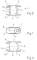
- the chain link 1 has two spaced apart from each other, in a longitudinal direction of the energy guiding chain, chain links 2, 3.
- Each link plate 2, 3 has an articulated body 6 and an articulated receptacle 7
- the joint body 6 is formed on an outside of the link plate 2 or 3.
- the joint body 6 and the joint receptacle 7 run essentially transversely to Longitudinal direction of the energy chain.
- the joint body 6 and the Joint receptacle 7 are spaced apart in the longitudinal direction of the link plate considered, trained.
- the link plates 2, 3 are connected to one another by cross members 4, 5.
- the Trusses 4, 5 are formed at a distance from one another.
- the trusses 4, 5 and the Chain links 2, 3 delimit a channel section 8 in which lines can be arranged are.
- Each cross member 4, 5 is substantially aligned with a longitudinal edge Chain link 2 or 3.
- the cross member 4 has a convexly curved section 9.
- the convex curved section 9 lies in an essentially transverse to the link plate 2 or 3rd trending level.
- the cross member 4 has an area 10 which is designed to correspond to the convexly curved section 9.
- the area 10 is opposite to section 9. Section 9 and area 10 are symmetrical with respect to a substantially parallel to the longitudinal axis of the Energy chain extending axis 11 is formed.
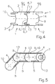
- FIGs 4 and 5 is a first embodiment of an inventive Energy chain 12 shown.
- the energy chain 12 is through Chain links 1 formed.
- the design of each chain link 1 corresponds the configuration of the chain link shown in Figures 1 to 3.
- the chain links 1 are articulated together. The articulation takes place via the joint bodies 6 which engage in the joint receptacles 7.
- Adjacent chain links 1 are each substantially perpendicular to the Longitudinal axis 14 extending pivot axis 13 pivotable. As from FIG. 4 can be seen, the area 10 of the cross member 4 is curved on the convex trained section 9 of the crossbar 4 of an adjacent chain link.
- the Trusses 4 are designed so that they in the longitudinal direction of the Energy chain 12 is considered to have an extension that is greater than that Distance between two outer joint axes 13 of two chain links. hereby receives the energy chain 12 a bias.
- Fig. 5 it is shown that the crossbars 5 of adjacent chain links with their respective end faces can be brought into contact, so that the crossbeams 5 Limit the radius of curvature of the energy chain.
- the articulated connection of adjacent chain links is carried out by articulated bodies 6 and Articulated receptacles 7.
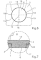
- the articulated connection of adjacent chain links is shown enlarged in Figures 6 and 7.
- Each joint body 6 is essentially cylindrical.
- the Joint receptacle 7 has an essentially oval cross section.
- the Joint body 6 and the joint receptacle 7 each have a jacket section on, which form a common connection area 16.
- the connection area 16 extends essentially in the longitudinal direction of the link plates 3.
- In the between the diametrically opposite connection areas 16 is between an outer jacket region 18 of the joint receptacle 7 and one Inner jacket region 19 formed a gap 17.
- the articulation has two substantially diametrically opposite column 17, which in the illustrated Embodiment are crescent. They extend in the circumferential direction of the Joint body 6 viewed from the connection area 16 to the opposite trained connection area 16.
- the chain links are about a pivot axis 15 which is substantially perpendicular to the hinge axis 13 stands, swiveling.
- adjacent Chain links each have a free space 20 through which one
- the adjacent chain links can be pivoted about the pivot axis 15 is made possible.
- a pivoting process about a pivot axis 15 slide the surfaces of the convexly curved section 9 and the correspondingly designed area 10 to each other.
- Each chain link 1 of the energy chain 12 is about a hinge axis 13 and a pivot axis 15 deflectable, so that adjacent chain links one Energy supply chain limited in space, i.e. in a three-dimensional space are deflectable.
- the energy chain 12 can be complete or in sections be formed with chain links 1 designed in this way.
- FIGS. 8 to 9 show a second embodiment of a chain link 21.
- Das Chain link 21 has two mutually spaced, opposing, chain links extending in a longitudinal direction of an energy guiding chain 22, 23 on.
- Each link plate 22, 23 has a joint body 26 and one Joint holder 27 on.
- the joint body 26 and the joint holder 27 extend essentially transversely to the longitudinal direction of an energy chain.
- the joint bodies 26 and the joint receptacle 27 of the link plates 22, 23 are so trained that these interlock when the chain links 21 together get connected.
- Each link plate 22, 23 is connected to one another by two cross members 24, 25.
- the crossbeams 25, 24 are essentially aligned with a longitudinal edge of the Chain link or 23. Limit the chain links 22, 23 and the crossbeams 24, 25 a channel section 28.
- the cross member 24 has a lengthwise direction of the energy chain extending extension 32.
- the extension 32 has a substantially convex curved section 29.
- the extension 32 and the convex curved Sections 29 are substantially symmetrical with respect to an axis 31 educated.
- the axis 31 runs essentially parallel to the longitudinal axis of FIG Power supply chain.
- the crossmember 24 has a concavely curved region 30 which is convex curved section 29 is formed opposite.
- the area is 30 formed corresponding to section 29.
- the area 30 is in one Recess 33 formed.
- the recess 33 extends from one End face 34 inwards into the cross member 24 and in the direction of the axis 31. Die Recess 33 tapers from end face 34 in the direction of region 30.
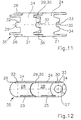
- FIG. 11 and 12 show a portion of an energy chain 35 through Chain links 21 is constructed.
- the adjacent chain links 21 are each around a hinge axis 36 can be deflected.
- the hinge axis 36 is due to the pairing Joint body 26 and joint receptacle 27 are formed.
- the extension 32 engages with the convexly curved section 29 the recess 33 with the concavely curved section 30.
- the trusses 24 and the extensions 32 and the recesses 33 are formed so that the Energy chain 35 is provided with a bias. This is not mandatory necessary.
- the radius of curvature is determined by the stops formed by the cross members 25 limited.
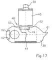
- FIGS. 13 to 17 show a further exemplary embodiment of a chain link 37 made of plastic for an energy chain for guiding cables.
- the Chain link 37 is made in one piece from a plastic, in particular injected.
- the chain link 37 has two spaced apart opposite, in a longitudinal direction of the energy chain extending, link plates 38, 39.
- the link plates are through one Traverse 41 connected to each other. Together with the traverse, they form 41 a U-shaped basic shape of the chain link 37.
- the cross member 41 extends into the overlap regions of the link plates, so that the cross member 41 forms a cover.
- Each link plate 38, 39 has an articulated body 42 and an articulated receptacle 46 on.
- the articulated body 42 is on an outer side of the link plate 38 or 39 formed, as shown in Fig. 14.
- the joint body 42 is made formed by slots 44 separate joint body segments 43. At its free end section, the joint body 42 has a radially outward direction Collar 45 also directed through the slots 44 divided. In the illustrated embodiment, each is around 120 ° C offset slots 44 are provided.
- the joint bodies 42 are formed in end regions of the link plates 38, 39. At the opposite end regions of the link plates 38, 39 are the Joint receptacles 46 are provided.
- the joint receptacles 46 have a essential elliptical cross section, so that the joint body in the corresponding joint receptacles are pivotable so that neighboring Chain links 37 are laterally deflectable to each other.
- the joint receptacle 46 has a circumferential recess 47. This The recess is essentially coaxial with the joint receptacle 46.
- the deep joint receptacle essentially corresponds to the thickness of the collar 45.
- a traverse 40 is connected in an articulated manner to the articulated bracket 39. This traverse is releasably connectable to the link plate 38 with its opposite end.
- the connection of the cross member 40 with the link plate 39 is by a Film hinge 48 formed.
- the film hinge 48, the link plate 39 and the Traverse 40 are integrally formed.
- the film hinge 48 is formed on an edge region of the link plate 39. Gaps 52 are provided on both sides of the film hinge 48, as shown in FIG. 17 shows.
- the film hinge is formed by a film web 49, which on a End connected to the link plate 39 and other ends to the cross member 40 is.
- the thickness of the film web 49 is significantly smaller than the thickness of the Chain link 39.
- recesses 50, 51 is provided, as shown in FIG. 15.
- the cross member 40 In the area of the film hinge 48, the cross member 40 has a transverse to Projection 53 extending in the longitudinal direction of the crossmember. In the closed State of the chain link 37 is the projection 53 on the edge 54 of the Recess 50, as shown in FIG. 16. This will be a relief of the film hinge 48 and thus a relief of the film web 49 is reached when a force is exerted on the cross member 40 and in the direction of the cross member 41.
- a locking element 55 is formed at the end region of the cross member 40 opposite the film hinge 48 .
- the locking element 55 is by a hook 56 educated.
- the hook 56 acts with a counter hook 57, which in one Free working of the edge area of the link plate 58 is formed. apart a web 58 for hook 56 is provided, which together with hook 56 delimits a space 59 into which the counter hook 57 engages.
- the web 58 lies with its one surface against the inner surface of the link plate 38, like this 16 can be seen. Through the web 58 there is mobility and thus stress on film hinge 48 is at least reduced, if not reduced completely avoided, since a movement of the traverse 40 in the longitudinal direction of the latter is prevented.
- the link plates 38, 39 and the cross members 40, 41 limit one Channel section 60, in which lines, in particular electrical lines can be.
- each chain link preferably has a stop element 61 at one end.
- stop surfaces 62 are provided.
- the stop elements 61 act with the stop surfaces 62 of an adjacent one Chain link together.
- the stop surfaces 62 are essentially one formed parallel to a central plane of the link plate.
- the stop surfaces are preferably designed equidistant from the central plane.
- the stop element 61 is also in the region of the central plane of the link plate educated.
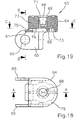
- FIGS. 18 to 21 show the preferred embodiment Embodiment of a connector 63 shown.
- the connector 63 is formed by a base body 64. With the base body 64 are two tabs 65 connected. The tabs 65 are spaced apart and each other trained opposite.
- Each link plate 65 has an articulated receptacle 66 on.
- the joint receptacle 66 has on the outer side surfaces of the Flap open 65 wells 67.
- the design of the joint receptacles 66 corresponds to the design of the Joint recordings of the chain links shown above, so that Connector 63 can be connected to the corresponding joint bodies. This is not necessarily. Depending on which end one Energy chain the connector should be provided, can Connector may also be provided with corresponding joint body, which in the corresponding joint receptacles can be introduced.
- a receptacle 68 is provided, in which a not shown connecting element can be introduced.
- the connector is on attached to a connection point.
- the Recording 68 formed transversely to the longitudinal axis of an energy chain. This is not mandatory.
- the joint can also be parallel to Longitudinal axis of the energy chain be formed. She can also do that Cut the longitudinal axis of the energy chain at an angle.
- the receptacle 68 is delimited by a wall 69.
- the wall 69 extends from a bottom wall 70 to a top wall 79.
- the wall 69 is on the Molded bottom wall 70.
- the wall 69 is through wall sectors 71, 73 educated. In the illustrated embodiment there are four wall sectors intended.
- the wall sectors are separated from one another by slots 72, such as this is shown in FIG. 21.
- the opposite wall sectors are 71 designed to be resilient, so that this with the not shown Connecting element form a snap connection.
- the wall sectors are 73 essentially rigid.
- An insertion opening 74 is provided within the base body 64.
- This Insertion opening 74 extends essentially transversely to the longitudinal direction of FIG Recording 68.
- the insertion opening 74 is through the bottom wall 70, the Cover wall 79 and the side walls 77 limited.
- the side walls 77 have in Area of the entry opening 90 in the insertion opening 74 protrusions 78.
- the projections 78 are directed towards one another.
- the clear width of the Entry opening 90 is smaller than the clear distance between the side walls 77, so that in the transition area between the projection 78 and the side wall 77 a stop surface 89 is formed, as can be seen from FIG. 21.
- the receptacle 68 extends through the bottom wall 70. Neighboring too the receptacle 68 is provided with a nose 88. This nose 88 extends from the bottom wall 70 of the base body 64 away.
- An insertion pocket 75 is provided below the bottom wall 70.
- the Insert pocket 75 is delimited by the bottom wall 70 and a web 76 Web 76 extends only over part of the bottom wall 70, so that the Recording 68 is released.
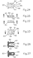
- a locking element 80 is shown in FIGS. 22 to 27.
- the Locking element 80 acts with the base body 64 of the connecting member 63 together, as will be explained below.
- the locking element 80 has a substantially U-shaped shape. It has two free legs 81, 82 which are shared by a base 83 are interconnected. The free legs 81, 82 are resilient educated. Each leg 81, 82 has one on its outer surface Stop 84 on the by a substantially parallel to the base 83 Surface is formed. The distance between the inner side surfaces of the legs 81, 82 essentially corresponds to the outer width of the wall 68.
- the tab 85 Spaced from the free legs 81, 82 and substantially parallel to a locking tab 85 is provided.
- the tab 85 has one Opening 86 on.
- the opening 86 is in the region of the free end face 87 intended.
- the locking element 80 is designed so that the free legs 81, 82 in the insertion opening 74 can be introduced.
- the securing tab 85 is in the Insert pocket 75 of the base body 64 can be inserted.
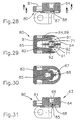
- Figures 28 to 31 show the connector with the locking element 80 in an assembly position.
- the free legs 81, 82 are in the Insert opening introduced. These are not on the outer surface of the Wall sectors 71, so that the wall sectors 71 are pivoted radially outwards.
- the wall sectors 71 can have depressions and / or on the inner surfaces 92 Have projections which with correspondingly formed projections or Wells of a connecting element, not shown, which in the Recording 68 can be introduced.
- the end face 87 of the Locking tab 85 on the nose 88 limits the displacement of the locking element 80 transversely to the receptacle 64.
- the locking element 80 is captive with the base body 64 connected.
- the stop surfaces 84, 89 are provided. Areas 84, 89 limit the mobility of the locking element 80, so that Locking element 80 without the free legs 81, 82 being compressed are not removable from the insertion opening 74.
- Fig. 34 shows the position of the securing tab 85 which it occupies when the Locked position is reached. In this position, the nose 88 engages in the Opening 86 a. In this position, an end portion of the Connecting element itself through the receptacle 68 into the opening 86 extend.
- the securing tab must move away from the base body 65 are moved so that the nose 88 no longer engages in the opening 86, so that the locking element 80 from the locking position into a Mounting position can be moved.
- the receptacle 68 is preferably rotationally symmetrical. In these engages an appropriately designed rotationally symmetrical Connecting element. As a result, a rotatability of the Connection member 63 reached about the longitudinal axis of the receptacle, whereby a Enables an energy chain to be deflected sideways becomes.
Landscapes
- Engineering & Computer Science (AREA)
- General Engineering & Computer Science (AREA)
- Mechanical Engineering (AREA)
- Electric Cable Arrangement Between Relatively Moving Parts (AREA)
Claims (29)
- Chaíne de transport d'énergie pour guider des lignes entre une connexion stationnaire et une connexion mobile, comportant des maillons de chaíne (1, 21, 37) en matière plastique, reliés les uns aux autres de manière articulée, qui limitent respectivement une section de canal (8, 28, 60) s'étendant en direction de la chaíne de transport d'énergie (12, 35), dans quel cas chaque maillon de chaíne (1, 21) présente deux éclisses de chaíne (2, 3, 22, 23 ; 38, 35), à distance l'une de l'autre, en vis-à-vis l'une de l'autre et s'étendant dans uns direction longitudinale de la chaíne de transport d'énergie (12, 35), lesquelles éclisses de chaíne (2, 3, 22, 23 ; 38, 35) sont reliées les unes aux autres par au moins une entretoise (4, 5, 24, 25, 40, 41), chaque éclisse de chaíne (2 , 3 ; 22, 23 ; 38, 39) a un corps d'articulation (6, 26, 42) et un logement d'articulation (7, 27, 46) qui s'étendent sensiblement de manière transversale à la direction longitudinale de la chaíne de transport d'énergie (12, 35), le corps d'articulation (6, 26, 42) d'une éclisse de chaíne (2 , 3 ; 22, 23 ; 38, 39) s'engageant dans le logement d'articulation (7, 27, 46) d'une éclisse de chaíne adjacente (2 ; 3, 22, 23 ; 38, 39), caractérisée en ce qu'un espace libre (20) est prévu respectivement entre les éclisses de chaíne (2 ; 3, 22, 23 ; 38, 39) de deux maillons de chaíne adjacents (1, 21, 37), les éclisses de chaíne (2, 3 ; 22, 23 ; 38, 39) se recouvrant partiellement, et en ce que le corps d'articulation (6, 26, 42) présente une surface d'enveloppe extérieure (18) et le logement d'articulation (7, 27, 46) une surface d'enveloppe intérieure (19) qui diffère de la surface d'enveloppe extérieure (18), de sorte qu'uniquement deux zones diamétralement opposées de ces surfaces d'enveloppe extérieure (18) et intérieure (19) sont disposées l'une contre l'autre.
- Chaíne de transport d'énergie selon la revendication 1, caractérisée en ce que les normales des zones d'enveloppe extérieure (18) et des zones d'enveloppe intérieure (19) s'étendent sensiblement de manière perpendiculaire à la direction longitudinale de la chaíne de transport d'énergie (12, 35).
- Chaíne de transport d'énergie selon la revendication 1 ou 2, caractérisée en ce que le corps d'articulation (6, 26, 42) est réalisé sensiblement en forme de cylindre et que le logement d'articulation (7, 27, 42) a une section transversale sensiblement ovale.
- Chaíne de transport d'énergie selon la revendication 1 ou 2, caractérisée en ce que le corps d'articulation (6, 26, 42) a une section transversale sensiblement ovale et le logement d'articulation (7, 27, 46) une section transversale circulaire.
- Chaíne de transport d'énergie selon l'une des revendications 1 à 4, caractérisée en ce que deux maillons de chaíne adjacents (1, 21, 37) sont pivotables relativement l'un à l'autre dans une zone d'angle jusqu'environ 45°.
- Chaíne de transport d'énergie selon l'une des revendications 1 à 5, caractérisée en ce que le corps d'articulation (42) est formé de segments de corps d'articulation (43) séparés les uns des autres par des fentes (44).
- Chaíne de transport d'énergie selon l'une des revendications 1 à 6, caractérisée en ce que le corps d'articulation (42) présente dans la zone de sa section d'extrémité libre une collerette (45) dirigée radialement vers l'extérieur.
- Chaíne de transport d'énergie selon la revendication 7, caractérisée en ce qu'une cavité (47) est prévue concentriquement à un logement d'articulation (46), dans laquelle la collerette (45) s'engage avec jeu.
- Chaíne de transport d'énergie selon l'une des revendications 1 à 8, caractérisée en ce que l'entretoise (4, 24) présente une section incurvée de façon convexe (9, 29), qui se trouve dans un plan s'étendant sensiblement de manière transversale par rapport à l'éclisse de chaíne (1 ; 21), et une zone (10, 30) opposée et réalisée de manière correspondante à la section incurvée de façon convexe (9 ; 29), la section (9, 29) de l'entretoise (4, 24) d'un maillon de chaíne (1, 21) s'engageant dans la zone (10, 30) de l'entretoise (4, 24) d'un maillon de chaíne adjacent (1, 21).
- Chaíne de transport d'énergie selon la revendication 9, caractérisée en ce que la section incurvée de façon convexe (29) est réalisée sur une zone d'extrémité libre d'une extension (32) qui s'étend en direction longitudinale de la chaíne de transport d'énergie, et en ce que l'entretoise (24) a un dégagement (33) qui émerge dans la zone (30), le dégagement (33) rétrécissant à partir d'une face frontale (34) de l'entretoise (24) en direction de la zone (30).
- Chaíne de transport d'énergie selon la revendication 9 ou 10, caractérisée en ce qu'au moins la section (9 ; 29) et la zone (10 ; 30) sont réalisées symétriquement par rapport à un axe (11 ; 31) s'étendant sensiblement de manière parallèle à l'axe longitudinal de la chaíne de transport d'énergie.
- Chaíne de transport d'énergie selon l'une des revendications 1 à 11, caractérisée en ce que deux maillons de chaíne adjacents (1 ; 21) présentent deux axes d'articulation extérieurs (13) se trouvant à distance l'un de l'autre, en ce que les maillons de chaíne adjacents (1 ; 21) ont des entretoises (4 ; 24) dont l'étendue totale entre les axes d'articulation (13) est plus grande que l'écartement entre les axes d'articulation extérieurs (13).
- Chaíne de transport d'énergie selon l'une des revendications 1 à 12, caractérisée en ce que qu'au moins deux maillons de chaíne adjacents (1 ; 21) présentent deux entretoises (5 ; 25) à distance l'une de l'autre, en vis-à-vis l'une de l'autre et s'étendant transversalement à la direction longitudinale de la chaíne de transport d'énergie (12 ; 35), dans quel cas dans une position étendue de la chaíne de transport d'énergie (12 ; 35) les entretoises (5 ; 25) des maillons de chaíne adjacents (1 ; 21) se trouvent dans un plan commun et sont à distance l'une de l'autre et dans quel cas ces entretoises (5 ; 25) sont disposées l'une contre l'autre dans une zone incurvée.
- Chaíne de transport d'énergie selon l'une des revendications 1 à 13, caractérisée en ce qu'avec une extrémité une entretoise (40) peut être reliée de façon détachable à une éclisse de chaíne (38) et à l'autre éclisse de chaíne (39) par une charnière film (48).
- Chaíne de transport d'énergie selon la revendication 14, caractérisée en ce que dans la zone de la charnière film (48) l'entretoise (40) a au moins une saillie (53), de sorte que dans une position fermée de l'entretoise (40) la saillie (53) s'applique sur un bord de l'éclisse de chaíne (39).
- Chaíne de transport d'énergie selon la revendication 14 ou 15, caractérisée en ce que l'entretoise (40) forme un couvercle.
- Chaíne de transport d'énergie selon l'une des revendications 1 à 16, caractérisée en ce qu'au moins une éclisse de chaíne (38, 39) présente à une extrémité un élément de butée (61) et à l'autre extrémité une surface de butée (62), la surface de butée (62) étant réalisée sensiblement de manière parallèle à un plan médian de l'éclisse de chaíne (38, 39).
- Chaíne de transport d'énergie selon l'une des revendications 1 à 17, dans quel cas celle-ci a au moins un maillon de connexion (63), caractérisée en ce que l'au moins un maillon de connexion (63) présente un corps de base (64) avec au moins un logement (68), dans lequel peut être introduit un élément de liaison fixé sur un point de connexion, et un élément de verrouillage (80) coopérant avec l'élément de base (68), lequel élément de verrouillage (80) est agencé de telle façon dans une ouverture d'insertion (74) du corps de base (64) de manière à pouvoir être déplacé que l'élément de liaison (80) peut être fixé au corps de base (64).
- Chaíne de transport d'énergie selon la revendication 18, caractérisée en ce que le logement (68) est limité par une paroi (69) qui est formée sur une paroi de fond (70) et qui est réalisée au moins partiellement de manière résiliente et la paroi (69) forme une liaison à cliquet avec l'élément de liaison.
- Chaíne de transport d'énergie selon la revendication 19, caractérisée en ce que la paroi (69) est formée par au moins deux secteurs de paroi (71, 73) qui sont séparés l'un de l'autre par des fentes (72).
- Chaíne de transport d'énergie selon la revendication 20, caractérisée en ce que quatre secteurs de paroi (71, 73) sont prévus, dans quel cas deux secteurs de paroi opposés (73) sont réalisés sensiblement de manière rigide et les deux autres secteurs de paroi opposés (71) sont réalisés sensiblement de manière résiliente.
- Chaíne de transport d'énergie selon la revendication 19, 20 ou 21, caractérisée en ce que l'élément de verrouillage (80) est relié au corps de base (64) de manière à pouvoir être déplacé, de sorte que dans une position de verrouillage l'élément de verrouillage (80) empêche au moins la capacité de déviation de la paroi (69) et que dans une autre position il la libère.
- Chaíne de transport d'énergie selon la revendication 22, caractérisée en ce que l'élément de verrouillage (80) est réalisé sensiblement en forme de U, dans quel cas dans une position de verrouillage les branches libres (81, 82) s'appliquent partiellement contre la paroi (69), notamment contre les secteurs résilients de paroi (71).
- Chaíne de transport d'énergie selon la revendication 23, caractérisée en ce que le corps de base (64) présente une ouverture d'insertion (74) dans laquelle l'élément de verrouillage (80) est fixé de manière à pouvoir être déplacé, dans quel cas dans la position de verrouillage les branches libres (81, 82) sont appliquées partiellement contre la paroi (69), notamment contre les secteurs résilients de paroi (71), et contre les surfaces latérales (77) de l'ouverture d'insertion (74).
- Chaíne de transport d'énergie selon la revendication 24, caractérisée en ce que l'élément de verrouillage (80) présente une éclisse de fixation (85) qui est réalisée à distance des branches (81, 82) et sensiblement de manière parallèle par rapport à celles-ci, l'élément de verrouillage (80) ne pouvant être amené en position de verrouillage qu'au cas où l'éclisse de fixation (85) serait libérée par l'élément de liaison.
- Chaíne de transport d'énergie selon la revendication 25, caractérisée en ce que le corps de base (64) a une protubérance (88) qui s'étend dans le plan de mouvement de l'éclisse de fixation (85), en ce que l'éclisse de fixation (85) a une ouverture (86) dans laquelle s'engage la protubérance (88) en position de verrouillage, l'éclisse de fixation (85) pouvant être déviée de telle manière par l'élément de liaison que celle-ci peut être amenée en position de verrouillage.
- Chaíne de transport d'énergie selon la revendication 26, caractérisée en ce que la protubérance (88) et l'ouverture (86) ont une telle forme qu'un déverrouillage automatique du verrouillage n'a pas lieu.
- Chaíne de transport d'énergie selon l'une des revendications 18 à 27, caractérisée en ce que le logement (68) pénètre complètement le corps de base (64).
- Chaíne de transport d'énergie selon l'une des revendications 18 à 28, caractérisée en ce que le logement (68) et l'élément de liaison sont réalisés à symétrie de révolution.
Applications Claiming Priority (3)
| Application Number | Priority Date | Filing Date | Title |
|---|---|---|---|
| DE19839575A DE19839575A1 (de) | 1998-08-31 | 1998-08-31 | Energieführungskette zum Führen von Leitungen mit räumlich beweglichen Kettengliedern |
| DE19839575 | 1998-08-31 | ||
| PCT/EP1999/006373 WO2000012913A1 (fr) | 1998-08-31 | 1999-08-30 | Chaine de guidage de l'energie pour guider des conducteurs dotee de maillons mobile dans l'espace |
Publications (2)
| Publication Number | Publication Date |
|---|---|
| EP1108157A1 EP1108157A1 (fr) | 2001-06-20 |
| EP1108157B1 true EP1108157B1 (fr) | 2003-10-15 |
Family
ID=7879277
Family Applications (1)
| Application Number | Title | Priority Date | Filing Date |
|---|---|---|---|
| EP99946066A Expired - Lifetime EP1108157B1 (fr) | 1998-08-31 | 1999-08-30 | Chaine de guidage de l'energie pour guider des conducteurs dotee de maillons mobile dans l'espace |
Country Status (5)
| Country | Link |
|---|---|
| US (1) | US6550232B1 (fr) |
| EP (1) | EP1108157B1 (fr) |
| JP (1) | JP4569854B2 (fr) |
| DE (2) | DE19839575A1 (fr) |
| WO (1) | WO2000012913A1 (fr) |
Cited By (1)
| Publication number | Priority date | Publication date | Assignee | Title |
|---|---|---|---|---|
| DE202017106108U1 (de) | 2017-10-09 | 2017-10-24 | Igus Gmbh | Leitungsführungssystem und Führungsrinne, insbesondere für hohe Verfahrgeschwindigkeiten |
Families Citing this family (27)
| Publication number | Priority date | Publication date | Assignee | Title |
|---|---|---|---|---|
| DE20002820U1 (de) * | 2000-02-16 | 2000-05-25 | Igus Spritzgußteile für die Industrie GmbH, 51147 Köln | Energieführungskette |
| IT1318855B1 (it) * | 2000-09-14 | 2003-09-10 | Giovanni Mauri | Catena portacavi per movimenti su piu' assi |
| DE10118328A1 (de) * | 2001-04-12 | 2002-11-21 | Kabelschlepp Gmbh | Verfahren zur Herstellung eines Kettengliedes sowie Kettenglied einer Energieführungskette |
| US20030021866A1 (en) * | 2001-07-24 | 2003-01-30 | Grain Processing Corporation | Method for making wine |
| JP3716987B2 (ja) * | 2002-11-28 | 2005-11-16 | 株式会社椿本チエイン | ケーブル類保護案内装置 |
| DE10343029A1 (de) * | 2003-09-16 | 2005-04-07 | Kabelschlepp Gmbh | Schiebetürsystem für ein Fahrzeug, insbesondere für ein Kraftfahrzeug mit einer Energieführungskette |
| JP4121446B2 (ja) * | 2003-11-17 | 2008-07-23 | 株式会社椿本チエイン | ケーブル保護案内装置 |
| DE10358752A1 (de) | 2003-12-12 | 2005-07-14 | Kabelschlepp Gmbh | Schiebetürsystem für ein Fahrzeug, insbesondere ein Kraftfahrzeug |
| DE102004022512A1 (de) * | 2004-05-05 | 2005-12-01 | Kabelschlepp Gmbh | Kettenglied für eine Energieführungskette sowie Energieführungskette mit erweitertem Nutzungsquerschnitt |
| US20060202526A1 (en) | 2005-03-08 | 2006-09-14 | Stephan Achs | Vehicle seat, especially a motor vehicle seat |
| JP4118306B2 (ja) * | 2006-03-28 | 2008-07-16 | 株式会社椿本チエイン | ケーブル類保護案内装置 |
| JP4118308B2 (ja) * | 2006-04-14 | 2008-07-16 | 株式会社椿本チエイン | ケーブル類保護案内装置 |
| US7677812B2 (en) * | 2006-07-31 | 2010-03-16 | Tyco Electronics Corporation | Strain relief boot for cable connector |
| JP4503658B2 (ja) * | 2008-04-25 | 2010-07-14 | 株式会社椿本チエイン | ケーブル類保護案内装置 |
| DE102008049246B4 (de) * | 2008-09-26 | 2014-12-31 | Tsubaki Kabelschlepp GmbH | Leitungsführungseinrichtung sowie Verfahren zum Herstellen eines Elementes einer Leitungsführungseinrichtung |
| DE202010004852U1 (de) * | 2010-04-09 | 2011-08-26 | TRUMPF Maschinen Grüsch AG | Laserbearbeitungsmaschine |
| DE102011102115A1 (de) * | 2011-05-20 | 2012-11-22 | Airbus Operations Gmbh | Flexible Kabelführung |
| DE102012112340B4 (de) * | 2012-12-14 | 2016-05-25 | Tsubaki Kabelschlepp GmbH | Energieführungseinheit sowie Energieführungseinrichtung zum Führen von Leitungen, Kabeln, Schläuchen oder dergleichen, insbesondere mit kleinen Krümmungsradien |
| JP6262627B2 (ja) * | 2014-09-24 | 2018-01-17 | 株式会社椿本チエイン | ケーブル類保護案内装置 |
| TWM506906U (zh) * | 2015-02-06 | 2015-08-11 | Molex Taiwan Ltd | 線纜導引保護鏈 |
| US9956928B2 (en) | 2015-06-30 | 2018-05-01 | Fca Us Llc | Track assembly for sliding vehicle door |
| US10686307B2 (en) * | 2015-12-14 | 2020-06-16 | Ppc Broadband, Inc. | Flexible channel molding assemblies |
| CN107053258A (zh) * | 2017-05-26 | 2017-08-18 | 绵阳伦奇机器人有限公司 | 一种拖链的铰接结构 |
| JP6804490B2 (ja) * | 2018-06-27 | 2020-12-23 | 矢崎総業株式会社 | ワイヤハーネス、該ワイヤハーネスを備えた給電装置 |
| DE202019100430U1 (de) * | 2019-01-25 | 2019-06-03 | Igus Gmbh | Trennsteg, Quersteg und Querboden für Energieführungsketten |
| JP7089232B2 (ja) * | 2019-02-28 | 2022-06-22 | 住友電装株式会社 | ワイヤハーネス用プロテクタおよびワイヤハーネス装置 |
| CN110933356B (zh) * | 2020-01-02 | 2024-08-02 | 福州米鱼信息科技有限公司 | 一种带有摄像装置的显示终端 |
Family Cites Families (21)
| Publication number | Priority date | Publication date | Assignee | Title |
|---|---|---|---|---|
| US1945357A (en) * | 1931-05-16 | 1934-01-30 | Link Belt Co | Chain |
| US3473769A (en) | 1967-01-06 | 1969-10-21 | Ibm | Retainer for flexible leads |
| US3804232A (en) | 1972-12-04 | 1974-04-16 | Rexnord Inc | Structurally balanced plastic conveyor chain |
| GB1585656A (en) | 1978-02-02 | 1981-03-11 | Mansign Eng Ltd | Chain link |
| DE3407169C2 (de) * | 1984-02-28 | 1986-01-23 | Kabelschlepp Gmbh, 5900 Siegen | Energieführungskette |
| US4590961A (en) * | 1985-08-16 | 1986-05-27 | Cooper Industries, Inc. | Modular rolling conductor support |
| JPH055311Y2 (fr) * | 1986-04-23 | 1993-02-12 | ||
| DE8717638U1 (de) | 1987-02-04 | 1989-07-06 | Klein, Ernst, 4000 Düsseldorf | Mittel- oder Endbefestigungsteil für kettenförmige Energieleitungsträger |
| WO1990011225A1 (fr) | 1988-02-17 | 1990-10-04 | Custom Plastics, Inc. | Conteneur pouvant passer d'une configuration plane a une configuration en forme de canal |
| DE8901955U1 (de) | 1989-02-18 | 1989-04-06 | Kabelschlepp Gmbh, 5900 Siegen | Energieführungskette |
| DE3930291C1 (en) | 1989-09-11 | 1991-04-18 | Igus Gmbh, 5060 Bergisch Gladbach, De | Power supply chain with removable covers - having snap-in claws engaging arresting cut=outs in upper edge regions of side walls of linking sections |
| DE4105653A1 (de) * | 1991-02-22 | 1992-09-03 | Kabelschlepp Gmbh | Energiefuehrungskette |
| DE59108590D1 (de) | 1991-11-26 | 1997-04-10 | Gore W L & Ass Gmbh | Schleppkettenersatz |
| DK170664B1 (da) * | 1992-04-21 | 1995-11-27 | Baeltix Maskinfabrikken As | Kædeledstransportør |
| DE9313011U1 (de) | 1993-08-30 | 1995-01-05 | W.L. Gore & Associates Gmbh, 85640 Putzbrunn | Zugentlastungsvorrichtung für eine Leitungsführungsanordnung |
| DE19544931A1 (de) * | 1995-12-01 | 1997-06-05 | Kabelschlepp Gmbh | Kettenglied einer Energieführungskette mit Zusatzkörper |
| DE29700917U1 (de) | 1997-01-21 | 1997-03-20 | Igus Spritzgußteile für die Industrie GmbH, 51147 Köln | Anschlußteil für eine Energiezuführungskette |
| WO1998040644A1 (fr) * | 1997-03-13 | 1998-09-17 | Kabelschlepp Gmbh | Element de protection muni d'un couvercle pouvant etre place dans deux differentes positions stables |
| US6107565A (en) * | 1998-11-17 | 2000-08-22 | A&A Manufacturing Co., Inc. | Covered energy transmission line carrier |
| US6174020B1 (en) | 1998-12-15 | 2001-01-16 | Daimlerchrysler Corporation | Sliding door system for vehicles |
| JP3356733B2 (ja) * | 1999-10-19 | 2002-12-16 | 株式会社椿本チエイン | ケーブルドラグチェーン |
-
1998
- 1998-08-31 DE DE19839575A patent/DE19839575A1/de not_active Ceased
-
1999
- 1999-08-30 WO PCT/EP1999/006373 patent/WO2000012913A1/fr active IP Right Grant
- 1999-08-30 DE DE59907388T patent/DE59907388D1/de not_active Expired - Lifetime
- 1999-08-30 JP JP2000567863A patent/JP4569854B2/ja not_active Expired - Fee Related
- 1999-08-30 US US09/786,027 patent/US6550232B1/en not_active Expired - Lifetime
- 1999-08-30 EP EP99946066A patent/EP1108157B1/fr not_active Expired - Lifetime
Cited By (2)
| Publication number | Priority date | Publication date | Assignee | Title |
|---|---|---|---|---|
| DE202017106108U1 (de) | 2017-10-09 | 2017-10-24 | Igus Gmbh | Leitungsführungssystem und Führungsrinne, insbesondere für hohe Verfahrgeschwindigkeiten |
| WO2019072777A1 (fr) | 2017-10-09 | 2019-04-18 | Igus Gmbh | Système de guidage de ligne et goulotte de guidage, en particulier pour vitesses de déplacement élevées |
Also Published As
| Publication number | Publication date |
|---|---|
| DE59907388D1 (de) | 2003-11-20 |
| DE19839575A1 (de) | 2000-03-09 |
| WO2000012913A1 (fr) | 2000-03-09 |
| JP2003521638A (ja) | 2003-07-15 |
| EP1108157A1 (fr) | 2001-06-20 |
| US6550232B1 (en) | 2003-04-22 |
| JP4569854B2 (ja) | 2010-10-27 |
Similar Documents
| Publication | Publication Date | Title |
|---|---|---|
| EP1108157B1 (fr) | Chaine de guidage de l'energie pour guider des conducteurs dotee de maillons mobile dans l'espace | |
| DE19541928C1 (de) | Energieführungskette | |
| EP0956465B1 (fr) | Maillon de chaine a traverse de separation inserable | |
| EP1076784B1 (fr) | Chaine de guidage d'elements de transport d'energie | |
| EP0384153B1 (fr) | Chaîne porteuse pour lignes de transport d'énergie | |
| EP0879367B1 (fr) | Chaine de guidage d'energie a butee de guidage | |
| EP1869744B1 (fr) | Dispositif de cablage et systeme comprenant un dispositif de cablage et un dispositif de retenue logeant ledit dispositif de cablage | |
| EP1283381B1 (fr) | Chaîne porteuse pour lignes de transport d'énergie et maillon | |
| DE19710489A1 (de) | Faltbares Schutzelement für Leitungen | |
| DE102007015276A1 (de) | Seitenbogenförderkette mit Innen- und Außenkettengliedern | |
| EP2799738B1 (fr) | Chaîne autoportante | |
| DE3615734C2 (fr) | ||
| EP2981737B1 (fr) | Chaîne de transport d'énergie | |
| WO2005108820A1 (fr) | Maillon d'une chaine de transmission d'energie, et chaine de transmission d'energie a plus grande section utile | |
| EP4073894B1 (fr) | Dispositif de guidage de ligne pour des applications de salle blanche, ainsi que chaîne de support et maillon de chaîne pour celui-ci | |
| DE10030985B4 (de) | Leitungsführungseinrichtung | |
| EP1084070B1 (fr) | Chaine transporteuse | |
| EP1705401A2 (fr) | Maillon pour une chaîne porteuse de lignes de transport d'énergie | |
| EP3586035B1 (fr) | Chaîne de guidage d'énergie et module à rouleaux | |
| EP4158223B1 (fr) | Chaîne porte-câbles à éléments de raccordement articulés flexibles, ainsi que pattes latérales et élément de raccordement articulé approprié | |
| DE19740896C2 (de) | Kettenglied mit verschwenkbarem Steg | |
| DE19948926A1 (de) | Kettenglied einer Energieführungskette | |
| DE20002500U1 (de) | Energieführungskette | |
| EP4011653B1 (fr) | Bande à plaques comprenant une plaque de flottaison glissée | |
| DE202021101933U1 (de) | Energieführungskette mit biegsamen Gelenkverbindern, sowie Seitenlaschen und Gelenkverbinder hierfür |
Legal Events
| Date | Code | Title | Description |
|---|---|---|---|
| PUAI | Public reference made under article 153(3) epc to a published international application that has entered the european phase |
Free format text: ORIGINAL CODE: 0009012 |
|
| 17P | Request for examination filed |
Effective date: 20010301 |
|
| AK | Designated contracting states |
Kind code of ref document: A1 Designated state(s): AT BE CH CY DE DK ES FI FR GB GR IE IT LI LU MC NL PT SE |
|
| 17Q | First examination report despatched |
Effective date: 20020325 |
|
| GRAH | Despatch of communication of intention to grant a patent |
Free format text: ORIGINAL CODE: EPIDOS IGRA |
|
| GRAS | Grant fee paid |
Free format text: ORIGINAL CODE: EPIDOSNIGR3 |
|
| GRAA | (expected) grant |
Free format text: ORIGINAL CODE: 0009210 |
|
| AK | Designated contracting states |
Kind code of ref document: B1 Designated state(s): DE FR IT |
|
| REG | Reference to a national code |
Ref country code: IE Ref legal event code: FG4D Free format text: GERMAN |
|
| REF | Corresponds to: |
Ref document number: 59907388 Country of ref document: DE Date of ref document: 20031120 Kind code of ref document: P |
|
| REG | Reference to a national code |
Ref country code: IE Ref legal event code: FD4D |
|
| ET | Fr: translation filed | ||
| PLBE | No opposition filed within time limit |
Free format text: ORIGINAL CODE: 0009261 |
|
| STAA | Information on the status of an ep patent application or granted ep patent |
Free format text: STATUS: NO OPPOSITION FILED WITHIN TIME LIMIT |
|
| 26N | No opposition filed |
Effective date: 20040716 |
|
| REG | Reference to a national code |
Ref country code: FR Ref legal event code: PLFP Year of fee payment: 17 |
|
| PGFP | Annual fee paid to national office [announced via postgrant information from national office to epo] |
Ref country code: DE Payment date: 20150824 Year of fee payment: 17 |
|
| PGFP | Annual fee paid to national office [announced via postgrant information from national office to epo] |
Ref country code: FR Payment date: 20150824 Year of fee payment: 17 |
|
| PGFP | Annual fee paid to national office [announced via postgrant information from national office to epo] |
Ref country code: IT Payment date: 20150831 Year of fee payment: 17 |
|
| REG | Reference to a national code |
Ref country code: DE Ref legal event code: R119 Ref document number: 59907388 Country of ref document: DE |
|
| REG | Reference to a national code |
Ref country code: FR Ref legal event code: ST Effective date: 20170428 |
|
| PG25 | Lapsed in a contracting state [announced via postgrant information from national office to epo] |
Ref country code: DE Free format text: LAPSE BECAUSE OF NON-PAYMENT OF DUE FEES Effective date: 20170301 Ref country code: FR Free format text: LAPSE BECAUSE OF NON-PAYMENT OF DUE FEES Effective date: 20160831 |
|
| PG25 | Lapsed in a contracting state [announced via postgrant information from national office to epo] |
Ref country code: IT Free format text: LAPSE BECAUSE OF NON-PAYMENT OF DUE FEES Effective date: 20160830 |