EP2799738B1 - Chaîne autoportante - Google Patents
Chaîne autoportante Download PDFInfo
- Publication number
- EP2799738B1 EP2799738B1 EP13002377.3A EP13002377A EP2799738B1 EP 2799738 B1 EP2799738 B1 EP 2799738B1 EP 13002377 A EP13002377 A EP 13002377A EP 2799738 B1 EP2799738 B1 EP 2799738B1
- Authority
- EP
- European Patent Office
- Prior art keywords
- chain
- spring
- hinge
- spring element
- stiffening
- Prior art date
- Legal status (The legal status is an assumption and is not a legal conclusion. Google has not performed a legal analysis and makes no representation as to the accuracy of the status listed.)
- Active
Links
- 238000005452 bending Methods 0.000 claims description 8
- 230000000295 complement effect Effects 0.000 claims description 5
- 230000005540 biological transmission Effects 0.000 description 7
- 230000007246 mechanism Effects 0.000 description 6
- 239000003351 stiffener Substances 0.000 description 6
- 230000000903 blocking effect Effects 0.000 description 3
- 238000010276 construction Methods 0.000 description 3
- 230000015572 biosynthetic process Effects 0.000 description 2
- 238000010516 chain-walking reaction Methods 0.000 description 2
- 238000009434 installation Methods 0.000 description 2
- 238000004519 manufacturing process Methods 0.000 description 2
- 239000000463 material Substances 0.000 description 2
- 230000002146 bilateral effect Effects 0.000 description 1
- 230000000694 effects Effects 0.000 description 1
- 230000002349 favourable effect Effects 0.000 description 1
- 230000003993 interaction Effects 0.000 description 1
- 230000036316 preload Effects 0.000 description 1
- 238000004804 winding Methods 0.000 description 1
Images


Classifications
-
- F—MECHANICAL ENGINEERING; LIGHTING; HEATING; WEAPONS; BLASTING
- F16—ENGINEERING ELEMENTS AND UNITS; GENERAL MEASURES FOR PRODUCING AND MAINTAINING EFFECTIVE FUNCTIONING OF MACHINES OR INSTALLATIONS; THERMAL INSULATION IN GENERAL
- F16G—BELTS, CABLES, OR ROPES, PREDOMINANTLY USED FOR DRIVING PURPOSES; CHAINS; FITTINGS PREDOMINANTLY USED THEREFOR
- F16G13/00—Chains
- F16G13/18—Chains having special overall characteristics
-
- F—MECHANICAL ENGINEERING; LIGHTING; HEATING; WEAPONS; BLASTING
- F16—ENGINEERING ELEMENTS AND UNITS; GENERAL MEASURES FOR PRODUCING AND MAINTAINING EFFECTIVE FUNCTIONING OF MACHINES OR INSTALLATIONS; THERMAL INSULATION IN GENERAL
- F16G—BELTS, CABLES, OR ROPES, PREDOMINANTLY USED FOR DRIVING PURPOSES; CHAINS; FITTINGS PREDOMINANTLY USED THEREFOR
- F16G13/00—Chains
- F16G13/02—Driving-chains
- F16G13/06—Driving-chains with links connected by parallel driving-pins with or without rollers so called open links
-
- F—MECHANICAL ENGINEERING; LIGHTING; HEATING; WEAPONS; BLASTING
- F16—ENGINEERING ELEMENTS AND UNITS; GENERAL MEASURES FOR PRODUCING AND MAINTAINING EFFECTIVE FUNCTIONING OF MACHINES OR INSTALLATIONS; THERMAL INSULATION IN GENERAL
- F16G—BELTS, CABLES, OR ROPES, PREDOMINANTLY USED FOR DRIVING PURPOSES; CHAINS; FITTINGS PREDOMINANTLY USED THEREFOR
- F16G13/00—Chains
- F16G13/18—Chains having special overall characteristics
- F16G13/20—Chains having special overall characteristics stiff; Push-pull chains
Definitions
- the present invention relates to a back stiffener chain, in particular for door and window drives, with a plurality of alternating chain links, which are each connected to each other via a chain link, and with a stiffening device which stiffens the back stiffener chain in a first hinge direction, with a plurality of alternating chain links, which are each connected to each other via a chain link, wherein a spring element is provided with at least a first spring arm, the spring element is supported on a chain link, the first spring arm to an adjacent chain link, with which it under the bias of the spring element movably in contact extends to inhibit a bend of the backstiffened chain in a first hinge direction, the chain links have link plates and the link plates of adjacent chain links are connected to each other via the chain link.
- the stiffening chain further comprises a stiffening device
- stiffening chain stiffened in a second hinge direction, and for forming the stiffening link plates of adjacent chain links support portions to stiffen the back stiffener chain in the second hinge direction, or stiffening tabs are provided, which are each arranged on at least one chain link and have frontal Abstützkonturen to stiffen the back stiff chain in the second hinge direction.
- the invention further relates to a corresponding chain drive with such a back-rigid chain.
- a bilateral back stiff chain is from the DE 10 2005 099 154 A1 known.
- the chain elements are pivoted radially inward on a chain drive wheel.
- the hinge openings of the link plates are formed as slots and have a game against the hinge pin, so that shortens the effective chain pitch in the push bar.
- At the ends of the hinge pin rollers are further provided, which leads in a separate rail guide the back-rigid chain in the push pad.
- the hinge openings designed as elongated holes in the push pad allow a reliable installation of the stiffening contours formed on the end faces of the link plates.
- the publication DE 1 180 318 B shows, for example, a backrest chain drive with alternating inner and outer chain links, wherein the contour of the link plates frontally has a stiffening device and the chain is guided in the push pad by means of rollers between the link plates in a guide channel.
- a back-rigid chain with identical forked chain links known, which have interlocking stiffening contours on their back.
- the publication DE 1 046 422 B1 discloses a further spine-type link chain with a locking mechanism which blocks pivoting of the chain links to each other and is disengaged by means of a lateral guide disengaged.
- Another locking mechanism of a back stiff chain shows the DE 20 2007 002 767 U1 in which a locking element which can be pivoted transversely to the chain running direction is disengaged by means of a guide rail.
- backstep chains and chain drives known in the prior art use very different concepts and designs in order to ensure stiffening of the chain in the push step, and at the same time to allow the chain to be deflected around a chain drive wheel.
- Many of the known spine chains are added after the stiffening behind the Kettenantriebsrad in the push pad by additional measures or the chains are secured by means of locking mechanisms in the second or in both directions of articulation.
- many of the previously used in the art backstroke chain drives have proven to be good in some cases, but sometimes complex stiffening and / or locking mechanisms, and complex structures are used, which often require additional space
- the JP H07 172786 A deals with a lifting chain for a forklift, the chain links are prestressed against each other by means of a leg spring. On each second hinge pin such a leg spring is pushed, the two legs are respectively supported on the neighboring bolts. The chain is therefore always pushed back from an extended position to the folded position.
- a toothed chain which has wire spring elements between the chain links. These wire spring elements are designed to give the chain a flexural rigidity.
- the GB 12985 A shows a roller chain. Some of the chain links have upwardly projecting projections on which a leaf spring element is arranged and gives the chain a certain spring elasticity.
- the present invention is therefore an object of the invention to provide a back-rigid chain and a chain drive, which allows for the simplest possible construction of the chain and the stiffening mechanism a secure stiffening of the chain in the push.
- a back-rigid chain Due to the spring element used here in the back-stiff chain, the bending of the chain in the first joint direction is only inhibited, so that the chain can transmit sufficient forces during overrun operation.
- the tendency of the back stiffener chain according to the invention to yield when acting transversely to the direction of thrust of the chain buckling forces is reduced according to the spring force, so that the chain yields during deflection around a sprocket and can be performed without loosening a locking mechanism or an elongation of the chain pitch around the sprocket ,
- the deflection of the back-rigid chain to the sprocket takes place against the spring force of the spring element.
- the spring element reduces the influence of vibrations and the polygon effect in the thrust chain of the backstack chain by the elastic bias between adjacent chain joints, so that even relatively small chain drive wheels can be used and an operation in a vibration loaded area is possible.
- the back-rigid chain according to the invention comprises a stiffening device which stiffens the back-stiff chain in the second joint direction.
- a stiffening device which stiffens the back-stiff chain in the second joint direction.
- a stiffening device allows a secure stiffening in the second joint direction and, correspondingly, a secure power transmission in the push-pull.
- a slight hyperextension in the second hinge direction can reliably prevent unintentional buckling of the chain during the power transmission in the push step.
- a second spring element with one or two spring arms can be provided, which also inhibits a bending of the backstacked chain in the second articulation direction.
- a first solution provides that the link plates of adjacent chain links have end-side support sections in order to stiffen the back-stiff chain in the second joint direction.
- the provision of frontal support sections allows without the use of additional functional straps a stiffening of the chain in the second hinge direction.
- the link plates are provided on the rear side facing the second joint direction with support sections which overlap in such a way that buckling of the chain in the second joint direction is prevented.
- Such link plates with support portions for stiffening a back-stiff chain in the second joint opening are for example in the DE 10 2011 107 047 A1 described.
- stiffening tabs are provided, wherein the stiffening tabs are each arranged on at least one chain link and have end-side section contours to stiffen the back-rigid chain in the second hinge direction. Due to the formation of complementary support contours on the two end faces of the stiffening tabs, the stiffening function always takes place in the plane of the stiffening tabs, so that the stiffening of the chain does not cause any lateral forces.
- conventional tabs can be used for all other link plates of the chain links.
- the spring element may comprise a second spring arm extending to a second adjacent chain link with which it is movably in contact under the bias of the spring element to inhibit the bending of the backstep chain in the first hinge direction.
- a second spring arm which extends from the spring-element supported on a chain link to a second adjacent chain-link opposite the first adjacent chain-link, allows inherent securing of the chain link in the first direction of articulation by the two spring arms so as to be without a guide on the adjacent spring element can be supported freely movable on the first or second adjacent chain joint.
- a favorable embodiment provides that the chain link has a hinge pin, wherein the hinge pin extends through the spring element to connect the spring element with the chain link. This allows independent of a fixation of the spring element on the chain joint secure support of the spring element. In particular, with two spring arms, the arrangement of the spring element around the hinge pin around a movable inherent kink protection allows.
- the spring element can be designed in a simple manner as a torsion spring.
- a bent from a spring wire torsion spring allows without further manufacturing steps Formation of one or two spring arms and a central opening for receiving the hinge pin of the chain link.
- a torsion spring therefore represents a particularly cost-effective embodiment of a suitable spring element.
- An expedient embodiment provides that the first spring arm and the second spring arm of the spring element bear free on both adjacent chain joints and are arranged displaceably to the two adjacent chain joints.
- the two spring arms can be arranged unfixed sliding on the adjacent chain joints of the supported chain link, so that they move in a buckling of the back-rigid chain at a deflection around an associated sprocket on the adjacent chain link.
- An unfixed positioning of the spring arms on the adjacent chain joints or on each of these chain links arranged spring elements allows easy installation without exact positioning of the spring arms in a corresponding guide.
- a particular embodiment provides that the chain links are alternately equipped with stiffening tabs and the stiffening tabs are each arranged on two adjacent chain joints.
- the stiffening tabs can replace the conventional link plates of the respective chain links, so that both the material usage and the width of the backstacked chain can be reduced.
- stiffening tabs are designed as intermediate tabs, the intermediate tabs are each arranged on a chain link and positioned between the link plates adjacent chain links and have complementary end-side Abstützkonturen.
- intermediate tabs formed stiffening tabs can be made with a relatively small wall thickness.
- the intermediate straps can stiffen the back-stiff chain in its second hinge direction safely and essentially torsion-free.
- the present invention relates to a chain drive with one of the above-described embodiments of the backstacked chain according to the invention and a sprocket for deflecting the backstiffened chain.
- the back-stiff chain is deflected in the first hinge direction against the bias of the spring element without loosening a lock.
- the sprocket can only deflect the chain in a linear drive of the back-rigid chain, if necessary intervene without form-fitting between the elements of the chain, or at the same time serve as a drive of the chain in a radial drive.
- the chain automatically stretches out of the bend due to the bias of the spring element in the first direction of articulation and thus enables a power transmission in the thrust direction of the chain.
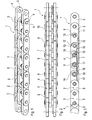
- back stiffener chain 1 includes alternating inner chain links 2 and outer chain links 3, which are each connected to each other via a chain link 4.
- the outer chain links 3 comprise two outer straps 5 arranged parallel to each other in a parallel distance and a center strap 7 arranged substantially centrally between the outer straps 5.
- the outer straps 5 and the middle strap 7 are connected to one another via a hinge pin 6 arranged perpendicularly to them.
- the hinge pins 6 also extend perpendicular to the chain longitudinal axis through the inner flaps 8 of the inner chain links 2.
- the inner flap 8 each has two hinge openings 9 through which the hinge pin 6 extends and is received to pivot the inner chain links 2 to the outer chain links 3 to enable.
- the hinge pin 6 is in corresponding hinge openings (not shown) of the outer chain plate 5 is pressed.
- the in the Fig. 1 as well as in the associated detailed representations in Fig. 2 to Fig. 4 illustrated inventive back-rigid chain 1 is designed as a leaf chain construction without sleeves or rollers between the inner plates. 8
- intermediate tabs 10 are arranged between the inner plates 8 of the inner chain links 2 and the center flaps 7 of the outer chain links 3 intermediate tabs 10 are arranged.
- the intermediate plates 10 have in the Embodiment used here, a hinge opening 11, through which the hinge pin 6 extends therethrough, and further at the in plan view Fig. 2
- the projecting Abstweilkontur 12 on the first end side of the inner plate 8 fits into the set-back stage 13 on the top side 14 of the back-stiffened chain 1 at a first end side of the intermediate plates 10 a projecting Abstützkontur 12 and on the second end side of the intermediate plate second end face of the next inner flap 8.
- the intermediate plate 10 terminates at a distance from the bottom 15 to 10 in the manufacture of the intermediate tabs save material and an unintentional blocking action in the direction of the first hinge direction when deflecting to avoid the sprocket or pulley.
- a spring element 16 is provided between the center flaps 7 and the second inner flap 8 of the inner chain link 2 in each case.
- the spring elements 16 each have a first spring arm 17 and a second spring arm 18.
- the spring element 16 has a central opening 19 through which the hinge pin 6 of the respective chain link 4 extends.
- the first spring arm 17 and the second spring arm 18 extend from this chain link 4 to respectively different sides (in the longitudinal direction of the chain) to the next chain joint 4 and lie from the bottom 15 to the chain links 4 and the respective spring elements 16 of these chain links 4th under the bias of the spring element 16 at.
- the first spring arm 17 of a spring element 16 and the second spring arm 18 of the next spring element 16 are arranged offset from each other transversely to the direction of the chain 1, so that they do not overlap and hinder each other in their spring action.
- the first spring arm 17 of the spring element 16 is located on the middle tabs 7 facing side of the spring elements 16 and the second spring arm 18 of the spring elements 16 on the inner plates 8 facing side of the spring elements 16.
- the spring elements 16 may also be formed as a torsion spring, which can be bent in one piece from a spring wire. In such a torsion spring form the ends of the spring wire at the same time the two spring arms 17, 18 and the winding of the spring wire to form the bias on the two spring arms 17, 18 simultaneously forms the opening 19 for receiving the hinge pin 6.
- back-rigid chain 1 shows the necessary for power transmission in the thrust ring on both sides stiffening of the chain 1.
- the chain 1 is stiffened at the top 14 for blocking the chain 1 in the second hinge direction by means of the intermediate plates 10.
- the supporting contour 12 protruding at the first end face of the intermediate lugs 10 engages the step 13 of the next intermediate lug 1 formed above the hinge opening 11 of the intermediate lugs 10, so that further bending of the backstacked chain 1 in this second hinge direction is prevented.
- the first joint direction In the direction of deflection about a sprocket wheel (not shown) of an associated chain drive, the first joint direction, the bending of the two-sided backstep chain 1 is only inhibited by the spring elements 16.
- the first spring arm 17 and the second spring arm 18 of the spring element 16 rest from the underside 15 of the chain 1 on the arranged on the hinge pin 6 of the adjacent chain links 4 spring elements 16 under the bias of the spring element 16.
- the two spring arms 17, 18 are in each case in contact with the adjacent chain link 4, they are neither fixed nor guided there.
- the two spring arms 17, 18 of the spring element 16 press the chain 1 by means of the bias of the spring element 16 against the first hinge direction until the blockage by the intermediate plates 10 prevents further movement in the direction of the second hinge direction.
- the back-stiff chain 1 extends in the longitudinal direction of the chain 1 and thus enables a power transmission in the thrust direction. Next prevents the bias of the spring elements 16 at the same time unintentional buckling of the back-stiffened chain on both sides. 1
- a drive of the chain by means of a linear drive or by means of a radial drive with a drive sprocket allow the spring elements 16 at a reversal of the double-backed chain 1 to a sprocket, pulley or guide a free deflection against the spring force of the spring elements 16, ie without a lock to solve on the back-rigid chain 1 or without an otherwise necessary leadership in the Schrangrang.
- the resistance to the buckling of the back-rigid chain 1 in the deflection around a sprocket, pulley or guide can be adjusted by the bias of the spring element 16 on the two spring arms 17, 18.
- the necessary force to deflect the chain 1 around the sprocket in the first direction of articulation is deflected by the driven sprocket applied itself or any other linear operation, so that in case of leakage from the sprocket, the bias of the spring elements 16 stiffen the spine-chain 1 automatically in the first joint direction.
- FIG. 5 A further embodiment of a spine-resistant chain 1 according to the invention is shown Fig. 5 , this back-rigid chain 1 is designed as a classic sleeve or roller chain. Also in this classic structure, inner chain links 2 and outer chain links 3 alternate with each other and are each connected to each other via a chain link 4.
- the inner chain links 2 each comprise parallel spaced inner plates 8, wherein the two inner plates 8 are connected to each other by means of sleeves 20. Through the sleeves 20 of the inner plates 8 each of the hinge pin 6 of the chain link 4 extends to connect the inner chain links 2 and the outer chain links 3 together.
- the hinge sleeve 20 of the inner chain link 2 is surrounded between the inner plates 8 by a hinge roller 21 to reduce the wear of the chain link 4 upon engagement in an associated sprocket.
- an intermediate plate 22 and a spring element 16 are provided on both sides of the chain 1, the intermediate plate 22 respectively adjacent to the outer plate 5 and the spring element 16 respectively on the inner plate borders.
- the alternatively designed intermediate plates 22 of this embodiment of a back-rigid chain 1 according to the invention are each positioned between two hinge pins 6 and have for fixing the intermediate plates 22 between the hinge pin 6 two circular-section-shaped contours 23 which rest against the hinge pin 6. Adjacent to the circular section-shaped contours 23, a support contour 24 is formed above the hinge pin 6. As in the partially cutaway side view of the backrest chain 1 in Fig. 6 can be seen, the abutment of Abstweilkontur 24 allows an intermediate tab 22 against a complementary AbstNeillkontur 24 of an adjacent intermediate plate 22, the stiffening of the back stiffener chain 1 in a second hinge direction, which is opposite to a deflection about an associated sprocket (not shown).
- the Abstützkonturen 24 of the intermediate plates 22 extend from the hinge pin 6 to the top 14 of the back-rigid chain 1.
- the intermediate plate 22 terminates at a distance from Bottom 15 and in addition, starting from the hinge pin 6 bevelled edges in order to avoid an unintentional blocking action in the direction of the first hinge direction.
- a spring element 16 is provided between the intermediate plates 22 and the inner plates 8 of the inner chain link 2, a spring element 16 is provided in each case.
- the spring elements 16 here also have a first spring arm 17 and a second spring arm 18, which extend from the receiving chain link 4 to different sides to the next chain link 4 and from the underside 15 at this chain joint 4 and the spring elements 16 mounted there under Preload applied.
- the spring element 16 is formed as a torsion spring, so that the first spring arm 17 and the second spring arm 18 are formed offset in the direction of the chain 1 to each other, and the spring arms 17, 18 adjacent spring elements 16 do not overlap.
- Fig. 7 shows a top perspective view of a chain drive 25 with a double-sided back stiffening chain 1, corresponding to the in the FIGS. 5 and 6 illustrated form of a classic sleeve or roller chain, which is moved at one end via a linear drive.
- the chain 1 is bent in this chain drive 25 by means of a deflection guide 26 in the first hinge direction and deflected in the direction of the desired thrust direction.
- the spring elements 16 cause stretching and stiffening of the chain 1 in the first hinge direction.
Claims (8)
- Chaine de poussée (1) à dos rigide, comprenant un grand nombre de maillons de chaine (2, 3) mutuellement alternés et reliés les uns aux autres respectivement par l'intermédiaire d'une articulation de chaine (4), chaine dans laquelle
il est prévu un élément de ressort (16) avec au moins un premier bras de ressort (17),
l'élément de ressort (16) s'appuie sur une articulation de chaine (4),
le premier bras de ressort (17) s'étend vers une articulation de chaine (4) voisine, avec laquelle il est en contact mobile sous précontrainte de l'élément de ressort (16), pour entraver une flexion dé la chaine de poussée (1) à dos rigide dans une première direction d'articulation,
les maillons de chaine (2, 3) présentent des plaques de chaine (5, 7, 8), et les plaques de chaine (5, 7, 8) de maillons de chaine (2, 3) voisins étant reliées mutuellement par l'intermédiaire de l'articulation de chaine (4),
caractérisée en ce qu'il est prévu un dispositif de rigidification, qui rigidifie la chaine de poussée (1) à dos rigide dans une deuxième direction d'articulation, et en ce que pour la réalisation du dispositif de rigidification, des plaques de chaine (5, 7, 8) de maillons de chaine (2, 3) voisins présentent des secteurs d'appui, en vue de rigidifier la chaine de poussée (1) à dos rigide dans la deuxième direction d'articulation, ou en ce que sont prévues des plaques de rigidification, qui sont agencées respectivement sur au moins une articulation de chaine (4) et présentent des contours d'appui (12, 13) frontaux, en vue de rigidifier la chaine de poussée (1) à dos rigide dans la deuxième direction d'articulation. - Chaine de poussée (1) à dos rigide selon la revendication 1,
caractérisée en ce que l'élément de ressort (16) présente un deuxième bras de ressort (18), et le deuxième bras de ressort (18) s'étend vers une deuxième articulation de chaine (4) voisine, avec laquelle il est en contact mobile sous précontrainte de l'élément de ressort (16), pour entraver la flexion de la chaine de poussée (1) à dos rigide dans la première direction d'articulation. - Chaine de poussée (1) à dos rigide selon la revendication 1 ou la revendication 2,
caractérisée en ce que l'articulation de chaine (4) comporte un tourillon d'articulation (6), le tourillon d'articulation (6) s'étendant à travers l'élément de ressort (16), en vue de relier l'élément de ressort (16) avec l'articulation de chaine (4). - Chaine de poussée (1) à dos rigide selon l'une des revendications 1 à 3,
caractérisée en ce que l'élément de ressort (16) est réalisé sous forme de ressort de torsion. - Chaine de poussée (1) à dos rigide selon l'une des revendications 2 à 4,
caractérisée en ce que le premier bras de ressort (17) et le deuxième bras de ressort (18) de l'élément de ressort (16) s'appuient librement sur les articulations de chaine (4) voisines, et sont agencés de manière coulissante par rapport aux deux articulations de chaine (4) voisines. - Chaine de poussée (1) à dos rigide selon l'une des revendications 1 à 5,
caractérisée en ce que les maillons de chaine (2,3) sont équipés alternativement de plaques de rigidification, et les plaques de rigidification sont agencées respectivement sur deux articulations de chaine (4) voisines. - Chaine de poussée (1) à dos rigide selon l'une des revendications 1 à 5,
caractérisée en ce que les plaques de rigidification sont réalisées sous forme de plaques intermédiaires (10, 22), et en ce que les plaques intermédiaires (10, 22) sont agencées respectivement sur une articulation de chaine (4), positionnées entre les plaques de chaine (5, 7, 8) de maillons de chaine (2, 3) adjacents, et présentent des contours d'appui frontaux (2, 3) complémentaires. - Entrainement à chaine comprenant une chaine de poussée (1) à dos rigide selon l'une des revendications 1 à 7.
Priority Applications (5)
| Application Number | Priority Date | Filing Date | Title |
|---|---|---|---|
| EP13002377.3A EP2799738B1 (fr) | 2013-05-03 | 2013-05-03 | Chaîne autoportante |
| ES13002377.3T ES2547255T3 (es) | 2013-05-03 | 2013-05-03 | Cadena inflexible en una dirección |
| CN201410331118.2A CN104235267B (zh) | 2013-05-03 | 2014-04-30 | 抗后弯链条 |
| US14/267,792 US9541160B2 (en) | 2013-05-03 | 2014-05-01 | Anti-backbend chain |
| TW103115889A TWI557342B (zh) | 2013-05-03 | 2014-05-02 | 抗後彎鏈條 |
Applications Claiming Priority (1)
| Application Number | Priority Date | Filing Date | Title |
|---|---|---|---|
| EP13002377.3A EP2799738B1 (fr) | 2013-05-03 | 2013-05-03 | Chaîne autoportante |
Publications (2)
| Publication Number | Publication Date |
|---|---|
| EP2799738A1 EP2799738A1 (fr) | 2014-11-05 |
| EP2799738B1 true EP2799738B1 (fr) | 2015-08-05 |
Family
ID=48366092
Family Applications (1)
| Application Number | Title | Priority Date | Filing Date |
|---|---|---|---|
| EP13002377.3A Active EP2799738B1 (fr) | 2013-05-03 | 2013-05-03 | Chaîne autoportante |
Country Status (5)
| Country | Link |
|---|---|
| US (1) | US9541160B2 (fr) |
| EP (1) | EP2799738B1 (fr) |
| CN (1) | CN104235267B (fr) |
| ES (1) | ES2547255T3 (fr) |
| TW (1) | TWI557342B (fr) |
Families Citing this family (7)
| Publication number | Priority date | Publication date | Assignee | Title |
|---|---|---|---|---|
| WO2014060775A1 (fr) | 2012-10-19 | 2014-04-24 | Renold Plc | Chaîne |
| CN104455248B (zh) * | 2014-11-15 | 2018-08-17 | 华北水利水电大学 | 一种链传动装置 |
| CN104894996B (zh) * | 2015-06-18 | 2016-05-11 | 合肥工业大学 | 一种单向弯曲传动链及其应用 |
| DE102017121706A1 (de) * | 2017-09-19 | 2019-03-21 | Iwis Antriebssysteme Gmbh & Co. Kg | Vorrichtung und Verfahren zur Ermittlung des Verschleißzustandes einer Kette |
| US20210023400A1 (en) * | 2019-07-22 | 2021-01-28 | Ramil Ravilyevich Musakaev | Seat for safety harness |
| US10774904B1 (en) * | 2019-12-18 | 2020-09-15 | Hasanen Mohammed Hussen | Torsional spring tensioning system for a power transmission chain |
| CN114044311A (zh) * | 2021-11-12 | 2022-02-15 | 安徽黄山恒久链传动有限公司 | 一种防逆向弯曲的鳞扳机链 |
Family Cites Families (24)
| Publication number | Priority date | Publication date | Assignee | Title |
|---|---|---|---|---|
| GB191412985A (en) * | 1914-05-27 | 1915-02-18 | Henry Smallwood Yoxall | Improvements in Driving Chains. |
| US2466639A (en) * | 1944-09-07 | 1949-04-05 | Diamond Chain Company Inc | Chain |
| US2638790A (en) * | 1950-10-21 | 1953-05-19 | Emil E Perron | Roller drive chain |
| DE1046422B (de) | 1957-10-25 | 1958-12-11 | Siemag Feinmech Werke Gmbh | Drucksteife Laschenkette, insbesondere zur Anwendung bei Windwerken fuer Schuetze, Schleusen, Hubtore, Stemmtore od. dgl. |
| DE1180318B (de) | 1961-02-13 | 1964-10-22 | Gevaert Photo Prod Nv | Hublader |
| DE1450699B1 (de) | 1961-05-18 | 1971-02-04 | Ct D Etudes Et D Applic Des Te | Gliederkette zur Übertragung von Zug- und Druckkräften |
| SU492695A1 (ru) * | 1974-06-06 | 1975-11-25 | Предприятие П/Я В-8721 | Цепь ограниченного изгиба |
| SU626287A1 (ru) * | 1975-03-10 | 1978-09-30 | Предприятие П/Я А-1125 | Жестка цепь |
| JPH0633993A (ja) * | 1992-03-16 | 1994-02-08 | Borg Warner Automot Kk | サイレントチェーン |
| JPH07172786A (ja) * | 1993-12-21 | 1995-07-11 | Komatsu Forklift Co Ltd | フォークリフトトラックの昇降装置におけるリフトチェーン |
| DE10047979B4 (de) * | 1999-10-13 | 2013-05-16 | Schaeffler Technologies AG & Co. KG | Kette |
| DE20102310U1 (de) | 2001-02-02 | 2001-04-26 | Arnold & Stolzenberg Gmbh | Rückensteife Kette |
| DE10206274A1 (de) * | 2002-02-15 | 2003-08-28 | Wilh Schlechendahl & Soehne Gm | Drucksteife Kette |
| US6662545B1 (en) * | 2002-11-05 | 2003-12-16 | Masakazu Yamamoto | Chain cover |
| US8002658B2 (en) * | 2003-09-03 | 2011-08-23 | Borgwarner Inc. | Chains for power transmission |
| CN2837608Y (zh) * | 2004-05-12 | 2006-11-15 | Vkr控股公司 | 推拉链以及致动器 |
| DE102005009154B4 (de) | 2005-03-01 | 2009-06-18 | Bosch Rexroth Pneumatics Gmbh | Schubkette zur Kraftübertragung von mindestens einem Kettenrad eines Kettengetriebes |
| EP1744079A1 (fr) | 2005-07-12 | 2007-01-17 | Joh. Winklhofer & Soehne GmbH und Co. KG | Chaîne rigide |
| EP1757838B1 (fr) * | 2005-08-22 | 2008-10-15 | Joh. Winklhofer & Soehne GmbH und Co. KG | Chaîne rigide d'entraînement |
| DE202007002767U1 (de) | 2007-02-26 | 2008-07-03 | Iwis Antriebssysteme Gmbh & Co. Kg | Rückensteife Kette mit Verriegelungsmechanismus |
| DE102007039680B4 (de) * | 2007-08-22 | 2009-06-04 | Kintec-Solution Gmbh | Gliederkette |
| CN201475252U (zh) * | 2009-06-30 | 2010-05-19 | 范骏行 | 一种微薄型导向托链 |
| US8336286B2 (en) * | 2010-02-10 | 2012-12-25 | Prince Castle LLC | Push chain with a bias spring to prevent buckling |
| DE102011107047B4 (de) | 2011-07-11 | 2019-12-12 | Iwis Antriebssysteme Gmbh & Co. Kg | Rückensteifer Kettenantrieb mit gleichmäßigem, stoßfreiem Kettenlauf |
-
2013
- 2013-05-03 ES ES13002377.3T patent/ES2547255T3/es active Active
- 2013-05-03 EP EP13002377.3A patent/EP2799738B1/fr active Active
-
2014
- 2014-04-30 CN CN201410331118.2A patent/CN104235267B/zh active Active
- 2014-05-01 US US14/267,792 patent/US9541160B2/en active Active
- 2014-05-02 TW TW103115889A patent/TWI557342B/zh not_active IP Right Cessation
Also Published As
| Publication number | Publication date |
|---|---|
| CN104235267B (zh) | 2017-01-11 |
| ES2547255T3 (es) | 2015-10-02 |
| US9541160B2 (en) | 2017-01-10 |
| TWI557342B (zh) | 2016-11-11 |
| TW201502397A (zh) | 2015-01-16 |
| US20140329632A1 (en) | 2014-11-06 |
| CN104235267A (zh) | 2014-12-24 |
| EP2799738A1 (fr) | 2014-11-05 |
Similar Documents
| Publication | Publication Date | Title |
|---|---|---|
| EP2799738B1 (fr) | Chaîne autoportante | |
| EP1503107B2 (fr) | Elément d'articulation pour chaîne porteuse de lignes de transport d'énergie | |
| EP1975093B1 (fr) | Chaîne d'alimentation à flexion latérale dotée d'articulations extérieures et intérieures | |
| EP1108157B1 (fr) | Chaine de guidage de l'energie pour guider des conducteurs dotee de maillons mobile dans l'espace | |
| EP0819226B1 (fr) | Chaine de guidage | |
| EP0336084B1 (fr) | Fermeture d'une ouverture, telle qu'une porte ou portail | |
| DE3032148C2 (de) | Kette für ein Umschlingungsgetriebe. | |
| EP1283381B1 (fr) | Chaîne porteuse pour lignes de transport d'énergie et maillon | |
| EP2839183B1 (fr) | Chaîne porte-câbles à rouleaux | |
| WO1999057457A1 (fr) | Chaine de guidage d'elements de transport d'energie | |
| DE4325259C2 (de) | Energieführungskette | |
| EP1757838B1 (fr) | Chaîne rigide d'entraînement | |
| EP3253994B1 (fr) | Maillon et chaîne de manutention à maillon | |
| EP1744079A1 (fr) | Chaîne rigide | |
| DE102016111542B4 (de) | Schubkette mit standardisiertem Endstück | |
| DE2032517A1 (de) | Rahmengetriebe für Fenster, Türen oder dergleichen | |
| EP1084070B1 (fr) | Chaine transporteuse | |
| DE102012001809B4 (de) | Zahnlose Gelenkkette mit asymmetrischen Laschen | |
| EP3586035B1 (fr) | Chaîne de guidage d'énergie et module à rouleaux | |
| EP1705401A2 (fr) | Maillon pour une chaîne porteuse de lignes de transport d'énergie | |
| EP3260735A1 (fr) | Chaine de poussée | |
| DE3928237C1 (fr) | ||
| EP1059467A1 (fr) | Chaíne rigide dans une direction | |
| WO2007121957A1 (fr) | Chaîne transporteuse | |
| DE2852075C3 (de) | Gliederkette |
Legal Events
| Date | Code | Title | Description |
|---|---|---|---|
| PUAI | Public reference made under article 153(3) epc to a published international application that has entered the european phase |
Free format text: ORIGINAL CODE: 0009012 |
|
| 17P | Request for examination filed |
Effective date: 20140117 |
|
| AK | Designated contracting states |
Kind code of ref document: A1 Designated state(s): AL AT BE BG CH CY CZ DE DK EE ES FI FR GB GR HR HU IE IS IT LI LT LU LV MC MK MT NL NO PL PT RO RS SE SI SK SM TR |
|
| AX | Request for extension of the european patent |
Extension state: BA ME |
|
| GRAP | Despatch of communication of intention to grant a patent |
Free format text: ORIGINAL CODE: EPIDOSNIGR1 |
|
| RIC1 | Information provided on ipc code assigned before grant |
Ipc: F16G 13/20 20060101AFI20150203BHEP |
|
| INTG | Intention to grant announced |
Effective date: 20150305 |
|
| GRAS | Grant fee paid |
Free format text: ORIGINAL CODE: EPIDOSNIGR3 |
|
| GRAA | (expected) grant |
Free format text: ORIGINAL CODE: 0009210 |
|
| AK | Designated contracting states |
Kind code of ref document: B1 Designated state(s): AL AT BE BG CH CY CZ DE DK EE ES FI FR GB GR HR HU IE IS IT LI LT LU LV MC MK MT NL NO PL PT RO RS SE SI SK SM TR |
|
| REG | Reference to a national code |
Ref country code: GB Ref legal event code: FG4D Free format text: NOT ENGLISH |
|
| REG | Reference to a national code |
Ref country code: CH Ref legal event code: EP |
|
| REG | Reference to a national code |
Ref country code: AT Ref legal event code: REF Ref document number: 740904 Country of ref document: AT Kind code of ref document: T Effective date: 20150815 |
|
| REG | Reference to a national code |
Ref country code: IE Ref legal event code: FG4D Free format text: LANGUAGE OF EP DOCUMENT: GERMAN |
|
| REG | Reference to a national code |
Ref country code: DE Ref legal event code: R096 Ref document number: 502013000955 Country of ref document: DE |
|
| REG | Reference to a national code |
Ref country code: ES Ref legal event code: FG2A Ref document number: 2547255 Country of ref document: ES Kind code of ref document: T3 Effective date: 20151002 |
|
| REG | Reference to a national code |
Ref country code: LT Ref legal event code: MG4D |
|
| REG | Reference to a national code |
Ref country code: NL Ref legal event code: MP Effective date: 20150805 |
|
| PG25 | Lapsed in a contracting state [announced via postgrant information from national office to epo] |
Ref country code: LV Free format text: LAPSE BECAUSE OF FAILURE TO SUBMIT A TRANSLATION OF THE DESCRIPTION OR TO PAY THE FEE WITHIN THE PRESCRIBED TIME-LIMIT Effective date: 20150805 Ref country code: GR Free format text: LAPSE BECAUSE OF FAILURE TO SUBMIT A TRANSLATION OF THE DESCRIPTION OR TO PAY THE FEE WITHIN THE PRESCRIBED TIME-LIMIT Effective date: 20151106 Ref country code: NO Free format text: LAPSE BECAUSE OF FAILURE TO SUBMIT A TRANSLATION OF THE DESCRIPTION OR TO PAY THE FEE WITHIN THE PRESCRIBED TIME-LIMIT Effective date: 20151105 Ref country code: LT Free format text: LAPSE BECAUSE OF FAILURE TO SUBMIT A TRANSLATION OF THE DESCRIPTION OR TO PAY THE FEE WITHIN THE PRESCRIBED TIME-LIMIT Effective date: 20150805 Ref country code: FI Free format text: LAPSE BECAUSE OF FAILURE TO SUBMIT A TRANSLATION OF THE DESCRIPTION OR TO PAY THE FEE WITHIN THE PRESCRIBED TIME-LIMIT Effective date: 20150805 |
|
| PG25 | Lapsed in a contracting state [announced via postgrant information from national office to epo] |
Ref country code: IS Free format text: LAPSE BECAUSE OF FAILURE TO SUBMIT A TRANSLATION OF THE DESCRIPTION OR TO PAY THE FEE WITHIN THE PRESCRIBED TIME-LIMIT Effective date: 20151205 Ref country code: PL Free format text: LAPSE BECAUSE OF FAILURE TO SUBMIT A TRANSLATION OF THE DESCRIPTION OR TO PAY THE FEE WITHIN THE PRESCRIBED TIME-LIMIT Effective date: 20150805 Ref country code: PT Free format text: LAPSE BECAUSE OF FAILURE TO SUBMIT A TRANSLATION OF THE DESCRIPTION OR TO PAY THE FEE WITHIN THE PRESCRIBED TIME-LIMIT Effective date: 20151207 Ref country code: HR Free format text: LAPSE BECAUSE OF FAILURE TO SUBMIT A TRANSLATION OF THE DESCRIPTION OR TO PAY THE FEE WITHIN THE PRESCRIBED TIME-LIMIT Effective date: 20150805 Ref country code: RS Free format text: LAPSE BECAUSE OF FAILURE TO SUBMIT A TRANSLATION OF THE DESCRIPTION OR TO PAY THE FEE WITHIN THE PRESCRIBED TIME-LIMIT Effective date: 20150805 Ref country code: SE Free format text: LAPSE BECAUSE OF FAILURE TO SUBMIT A TRANSLATION OF THE DESCRIPTION OR TO PAY THE FEE WITHIN THE PRESCRIBED TIME-LIMIT Effective date: 20150805 |
|
| PG25 | Lapsed in a contracting state [announced via postgrant information from national office to epo] |
Ref country code: NL Free format text: LAPSE BECAUSE OF FAILURE TO SUBMIT A TRANSLATION OF THE DESCRIPTION OR TO PAY THE FEE WITHIN THE PRESCRIBED TIME-LIMIT Effective date: 20150805 |
|
| PG25 | Lapsed in a contracting state [announced via postgrant information from national office to epo] |
Ref country code: CZ Free format text: LAPSE BECAUSE OF FAILURE TO SUBMIT A TRANSLATION OF THE DESCRIPTION OR TO PAY THE FEE WITHIN THE PRESCRIBED TIME-LIMIT Effective date: 20150805 Ref country code: SK Free format text: LAPSE BECAUSE OF FAILURE TO SUBMIT A TRANSLATION OF THE DESCRIPTION OR TO PAY THE FEE WITHIN THE PRESCRIBED TIME-LIMIT Effective date: 20150805 Ref country code: EE Free format text: LAPSE BECAUSE OF FAILURE TO SUBMIT A TRANSLATION OF THE DESCRIPTION OR TO PAY THE FEE WITHIN THE PRESCRIBED TIME-LIMIT Effective date: 20150805 Ref country code: DK Free format text: LAPSE BECAUSE OF FAILURE TO SUBMIT A TRANSLATION OF THE DESCRIPTION OR TO PAY THE FEE WITHIN THE PRESCRIBED TIME-LIMIT Effective date: 20150805 |
|
| REG | Reference to a national code |
Ref country code: DE Ref legal event code: R097 Ref document number: 502013000955 Country of ref document: DE |
|
| REG | Reference to a national code |
Ref country code: FR Ref legal event code: PLFP Year of fee payment: 4 |
|
| PG25 | Lapsed in a contracting state [announced via postgrant information from national office to epo] |
Ref country code: RO Free format text: LAPSE BECAUSE OF FAILURE TO SUBMIT A TRANSLATION OF THE DESCRIPTION OR TO PAY THE FEE WITHIN THE PRESCRIBED TIME-LIMIT Effective date: 20150805 |
|
| PLBE | No opposition filed within time limit |
Free format text: ORIGINAL CODE: 0009261 |
|
| STAA | Information on the status of an ep patent application or granted ep patent |
Free format text: STATUS: NO OPPOSITION FILED WITHIN TIME LIMIT |
|
| 26N | No opposition filed |
Effective date: 20160509 |
|
| PG25 | Lapsed in a contracting state [announced via postgrant information from national office to epo] |
Ref country code: SI Free format text: LAPSE BECAUSE OF FAILURE TO SUBMIT A TRANSLATION OF THE DESCRIPTION OR TO PAY THE FEE WITHIN THE PRESCRIBED TIME-LIMIT Effective date: 20150805 Ref country code: BE Free format text: LAPSE BECAUSE OF NON-PAYMENT OF DUE FEES Effective date: 20160531 |
|
| PG25 | Lapsed in a contracting state [announced via postgrant information from national office to epo] |
Ref country code: LU Free format text: LAPSE BECAUSE OF FAILURE TO SUBMIT A TRANSLATION OF THE DESCRIPTION OR TO PAY THE FEE WITHIN THE PRESCRIBED TIME-LIMIT Effective date: 20160503 |
|
| REG | Reference to a national code |
Ref country code: CH Ref legal event code: PL |
|
| PG25 | Lapsed in a contracting state [announced via postgrant information from national office to epo] |
Ref country code: LI Free format text: LAPSE BECAUSE OF NON-PAYMENT OF DUE FEES Effective date: 20160531 Ref country code: CH Free format text: LAPSE BECAUSE OF NON-PAYMENT OF DUE FEES Effective date: 20160531 |
|
| REG | Reference to a national code |
Ref country code: IE Ref legal event code: MM4A |
|
| REG | Reference to a national code |
Ref country code: FR Ref legal event code: PLFP Year of fee payment: 5 |
|
| PG25 | Lapsed in a contracting state [announced via postgrant information from national office to epo] |
Ref country code: IE Free format text: LAPSE BECAUSE OF NON-PAYMENT OF DUE FEES Effective date: 20160503 |
|
| REG | Reference to a national code |
Ref country code: FR Ref legal event code: PLFP Year of fee payment: 6 |
|
| PG25 | Lapsed in a contracting state [announced via postgrant information from national office to epo] |
Ref country code: SM Free format text: LAPSE BECAUSE OF FAILURE TO SUBMIT A TRANSLATION OF THE DESCRIPTION OR TO PAY THE FEE WITHIN THE PRESCRIBED TIME-LIMIT Effective date: 20150805 Ref country code: HU Free format text: LAPSE BECAUSE OF FAILURE TO SUBMIT A TRANSLATION OF THE DESCRIPTION OR TO PAY THE FEE WITHIN THE PRESCRIBED TIME-LIMIT; INVALID AB INITIO Effective date: 20130503 |
|
| PG25 | Lapsed in a contracting state [announced via postgrant information from national office to epo] |
Ref country code: MT Free format text: LAPSE BECAUSE OF FAILURE TO SUBMIT A TRANSLATION OF THE DESCRIPTION OR TO PAY THE FEE WITHIN THE PRESCRIBED TIME-LIMIT Effective date: 20150805 Ref country code: MC Free format text: LAPSE BECAUSE OF FAILURE TO SUBMIT A TRANSLATION OF THE DESCRIPTION OR TO PAY THE FEE WITHIN THE PRESCRIBED TIME-LIMIT Effective date: 20150805 Ref country code: CY Free format text: LAPSE BECAUSE OF FAILURE TO SUBMIT A TRANSLATION OF THE DESCRIPTION OR TO PAY THE FEE WITHIN THE PRESCRIBED TIME-LIMIT Effective date: 20150805 Ref country code: MK Free format text: LAPSE BECAUSE OF FAILURE TO SUBMIT A TRANSLATION OF THE DESCRIPTION OR TO PAY THE FEE WITHIN THE PRESCRIBED TIME-LIMIT Effective date: 20150805 |
|
| PG25 | Lapsed in a contracting state [announced via postgrant information from national office to epo] |
Ref country code: BG Free format text: LAPSE BECAUSE OF FAILURE TO SUBMIT A TRANSLATION OF THE DESCRIPTION OR TO PAY THE FEE WITHIN THE PRESCRIBED TIME-LIMIT Effective date: 20150805 |
|
| PG25 | Lapsed in a contracting state [announced via postgrant information from national office to epo] |
Ref country code: AL Free format text: LAPSE BECAUSE OF FAILURE TO SUBMIT A TRANSLATION OF THE DESCRIPTION OR TO PAY THE FEE WITHIN THE PRESCRIBED TIME-LIMIT Effective date: 20150805 Ref country code: TR Free format text: LAPSE BECAUSE OF FAILURE TO SUBMIT A TRANSLATION OF THE DESCRIPTION OR TO PAY THE FEE WITHIN THE PRESCRIBED TIME-LIMIT Effective date: 20150805 |
|
| REG | Reference to a national code |
Ref country code: AT Ref legal event code: MM01 Ref document number: 740904 Country of ref document: AT Kind code of ref document: T Effective date: 20180503 |
|
| PG25 | Lapsed in a contracting state [announced via postgrant information from national office to epo] |
Ref country code: AT Free format text: LAPSE BECAUSE OF NON-PAYMENT OF DUE FEES Effective date: 20180503 |
|
| PGFP | Annual fee paid to national office [announced via postgrant information from national office to epo] |
Ref country code: FR Payment date: 20210521 Year of fee payment: 9 |
|
| PGFP | Annual fee paid to national office [announced via postgrant information from national office to epo] |
Ref country code: ES Payment date: 20210618 Year of fee payment: 9 |
|
| PGFP | Annual fee paid to national office [announced via postgrant information from national office to epo] |
Ref country code: IT Payment date: 20220531 Year of fee payment: 10 Ref country code: GB Payment date: 20220517 Year of fee payment: 10 |
|
| PG25 | Lapsed in a contracting state [announced via postgrant information from national office to epo] |
Ref country code: FR Free format text: LAPSE BECAUSE OF NON-PAYMENT OF DUE FEES Effective date: 20220531 |
|
| REG | Reference to a national code |
Ref country code: ES Ref legal event code: FD2A Effective date: 20230703 |
|
| PG25 | Lapsed in a contracting state [announced via postgrant information from national office to epo] |
Ref country code: ES Free format text: LAPSE BECAUSE OF NON-PAYMENT OF DUE FEES Effective date: 20220504 |
|
| PGFP | Annual fee paid to national office [announced via postgrant information from national office to epo] |
Ref country code: DE Payment date: 20230519 Year of fee payment: 11 |
|
| P01 | Opt-out of the competence of the unified patent court (upc) registered |
Effective date: 20230724 |
|
| GBPC | Gb: european patent ceased through non-payment of renewal fee |
Effective date: 20230503 |