EP1705401A2 - Maillon pour une chaîne porteuse de lignes de transport d'énergie - Google Patents
Maillon pour une chaîne porteuse de lignes de transport d'énergie Download PDFInfo
- Publication number
- EP1705401A2 EP1705401A2 EP06005393A EP06005393A EP1705401A2 EP 1705401 A2 EP1705401 A2 EP 1705401A2 EP 06005393 A EP06005393 A EP 06005393A EP 06005393 A EP06005393 A EP 06005393A EP 1705401 A2 EP1705401 A2 EP 1705401A2
- Authority
- EP
- European Patent Office
- Prior art keywords
- chain link
- frame web
- link according
- chain
- frame
- Prior art date
- Legal status (The legal status is an assumption and is not a legal conclusion. Google has not performed a legal analysis and makes no representation as to the accuracy of the status listed.)
- Withdrawn
Links
Images


Classifications
-
- F—MECHANICAL ENGINEERING; LIGHTING; HEATING; WEAPONS; BLASTING
- F16—ENGINEERING ELEMENTS AND UNITS; GENERAL MEASURES FOR PRODUCING AND MAINTAINING EFFECTIVE FUNCTIONING OF MACHINES OR INSTALLATIONS; THERMAL INSULATION IN GENERAL
- F16G—BELTS, CABLES, OR ROPES, PREDOMINANTLY USED FOR DRIVING PURPOSES; CHAINS; FITTINGS PREDOMINANTLY USED THEREFOR
- F16G13/00—Chains
- F16G13/12—Hauling- or hoisting-chains so called ornamental chains
- F16G13/16—Hauling- or hoisting-chains so called ornamental chains with arrangements for holding electric cables, hoses, or the like
Definitions
- the invention relates to a chain link for an energy guide chain according to the preamble of claim 1.
- Known chain links for power transmission chains have two side links delimiting the chain link, which are connected to one another and with the connecting elements include a guide channel for lines. It is possible that the side members are integrally connected to each other and together with an integrally formed connecting element form a U-member, wherein the base of the U forming integrally formed connecting element limits the guide channel up or down. In this case, only a frame web is necessary to complete the chain link at the base of the U opposite side. It is also possible that the two side members are separate components, which are connected to each other by two frame bars top and bottom. In both cases, the frame webs are attached with their opposite end sides of each one of the side members, for example latched. In order to make the guide channel of the energy chain accessible from the outside, the frame webs must be removed from the side members and stored at a collection point. This is perceived as too expensive.
- the invention is based on the idea that after removing only one of the two a frame web attached to the side members fasteners, the interior of the chain link is accessible by pivoting the frame web, although the frame web is attached at its other end to one of the side members.
- the chain link can be opened either on one side or on the other.
- the side members advantageously have at least one pin on their mutually facing inner sides, through which the pivot axis extends for the frame web.
- the side members each have two spaced-apart pins.
- the at least one frame web then expediently has at its inner side facing the interior of the chain link to the pin complementary recesses for receiving the pin. This results in a simple, yet stable, even after frequent pivoting of the frame web relative to the side member durable connection.
- the recesses are preferably arcuate with at least partially round cross-section, so that they are suitable for receiving round pins.
- the at least one frame web expediently at its end sides in each case two at the same distance as the pin to each other arranged recesses.
- Each of these recesses is intended for receiving one of the pins.
- the at least one frame web between the end spaced-apart recesses has on its inner side a flat inner surface. A flat inner surface reduces the wear of lying on her, run in the chain link lines.
- the fastening elements expediently have at least one holding element for reaching over the outside of the at least one frame web facing away from the inside.
- the holding elements advantageously each have a holding surface for engagement with a complementary contact surface on the outside of the at least one frame web.
- the frame web is then securely held between the pin and the retaining elements.
- the contact surfaces are preferably parts of cylinder jacket surfaces, in this case preferably half cylinder jacket surfaces, wherein the support surfaces extend over more than half the circumference of the contact surfaces. This ensures the pivotability of the frame web with respect to the side member to which it is attached. When pivoting the frame web relative to the side member, the support surfaces slide over the contact surfaces up to a stop.
- the fastening elements expediently have a plurality of holding elements arranged at a distance from each other.
- the at least one frame web then also has a plurality of contact surfaces, which are arranged at the same distance from each other as the holding elements. Between the mutually spaced contact surfaces, the at least one frame web advantageously on reinforcing ribs extending from one to the other end side. The reinforcing ribs give the frame web increased stability.
- the fastening elements each have at least one support plate, from which protrudes the at least one retaining element.
- the support plate further expediently carries a latching hook for latching in a recess in the side members.
- the side members each advantageously have a recess on its outer side for insertion of the carrier plate and at least one opening extending from the outer side to the inner side for passing through the at least one holding element. The depth of the recess is preferably such that the carrier plate can be completely sunk into it and is aligned with the outer surface of the side member.
- the at least one frame web consists of in one direction from its one end side to its other end side juxtaposed identical sections with recesses on the inside and contact surfaces on the outside.
- the frame bar is thus suitable for chain links of different widths. For narrower chain links only a portion of the sections must be removed by sawing or canceling.
- the width of the chain link is always a multiple of the length of a portion of the frame web.
- the recesses can also serve the attachment of the guide channel dividing dividers.
- the at least one frame web and / or the fastening elements are in one piece, preferably made of plastic as an injection molded part. This allows a cost-effective mass production.
- the side members are interconnected by an upper, a ceiling of the chain link forming the first frame web and a similar lower, a bottom of the chain link forming the second frame web, the first frame web after removing one of its fasteners up, the second frame web after Removal of one of its fasteners is pivotable downwards.
- the interior of the chain link is thus accessible both from above and from below.
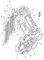
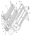
- the chain links 10 shown in the figures for an energy guide chain each have two side members 12, 13 and the side members 12, 13 in pairs connecting upper and lower frame webs 14, 16.
- the side members 12, 13 and the frame webs 14, 16 define a guide channel 17 for pipes such as hoses and cables.
- the frame webs 14, 16 are each on two opposite end sides 18, 19 releasably attached to the side members-12, 13.
- the frame webs 14, 16 are integrally made of plastic as injection molded parts. They consist of a plurality of identical sections, which adjoin one another in a longitudinal direction extending between the end sides 18, 19. At the guide channel 17 facing inside 22, the frame webs 14, 16 in each section on two opposite, open to their longitudinal sides recesses 24.
- the recesses 24 are arcade-shaped and terminate in each case with a semicircular in cross-section arc. Between the recesses 24 of each section 20 extends on the inner side 22 of the frame webs 14, 16, a flat inner surface 26 between the two end sides 18, 19. At the inner side 22 opposite outer side 28, the frame webs 14, 16 in each of their sections 20th four contact surfaces 30, which are formed as parts of cylinder jacket surfaces. The abutment surfaces 30 of each section 20 are spaced from each other, extending between them in the longitudinal direction of the frame webs 14, 16 extending reinforcing ribs 32. The two outer, on the longitudinal sides of the frame webs 14, 16 adjacent contact surfaces 30 have a larger radius than the two inner contact surfaces 30, which are half cylinder jacket surfaces.
- each of the paragraphs 36 two pins 38 are formed, which have a round cross-section, and a common, extending in the longitudinal direction of the energy chain drag center axis.
- the pins 38 are received in the recesses 24 of the end sides 18, 19 forming portions of the frame webs 14, 16. Due to the semicircular, complementary to the outer contour of the pin 38 formed inner contour of the recesses 24, the frame webs 14, 16 relative to the side members 12, 13 pivotally mounted on the pin 38, wherein the central axis of the pin 38 forms the pivot axis.
- fasteners 40 are used, which are integrally made as injection molded plastic parts.
- the fastening elements 40 have a carrier plate 42 and four holding elements 44 formed on the carrier plate 42.
- Recesses 48 are formed on the outer sides 46 of the side members 12, 13, into which the fastening elements 40 for fastening the frame webs 14, 16 are inserted.
- four apertures 50 extend from the outside 46 to the inside 34 of the side members 12, 13.
- the holding elements 44 engage and engage over the frame webs 14, 16 on the outside 28.
- each of the holding elements 44 comes with a holding surface 52 on a contact surface 30 to the plant.
- the holding surfaces 52 have the same radius of curvature as the contact surfaces 30 against which they rest. However, they extend over a maximum of half the circumference of the contact surfaces 30.
- a latching hook 54 is formed, which is inserted to lock the fastener 40 on the side member 12, 13 in a recess 56 in the recess 48 and latched.
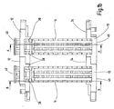
- the frame web can be folded up or down about the pivot axis at its opposite end side 19, as in Figs. 1a to 1d shown.
- pivoting the frame web 14, 16 relative to the side member 13 to which it is attached slide the support surfaces 52 via the complementary contact surfaces 30.
- the holding surfaces 52 extend over more than half the circumference of the contact surfaces 30, the frame web 14, 16 to be pivoted at least 90 ° about the pivot axis, so that the guide channel 17 is made accessible.
- the number of holding elements 44 per fastening element 40 and the number of contact surfaces 30 per section 20 of the frame webs 14, 16 need not be four.
- the invention relates to a chain link for a power transmission chain with two side members 12, 13 and at least one of the side members 12, 13 interconnecting frame web 14, 16 which is secured at its opposite end sides 18, 19 on each of the side members 12, 13.
- the at least one frame web 14, 16 is releasably secured to both side members 12, 13 by means of a detachable fastener 40 and is pivotable about one pivot axis with respect to the side member 13 upon release of the attachment at one end side 18 at which its other End side 19 is attached.
Landscapes
- Engineering & Computer Science (AREA)
- General Engineering & Computer Science (AREA)
- Mechanical Engineering (AREA)
- Electric Cable Arrangement Between Relatively Moving Parts (AREA)
- Devices For Conveying Motion By Means Of Endless Flexible Members (AREA)
Applications Claiming Priority (1)
| Application Number | Priority Date | Filing Date | Title |
|---|---|---|---|
| DE200510013430 DE102005013430A1 (de) | 2005-03-21 | 2005-03-21 | Kettenglied für eine Energieführungskette |
Publications (2)
| Publication Number | Publication Date |
|---|---|
| EP1705401A2 true EP1705401A2 (fr) | 2006-09-27 |
| EP1705401A3 EP1705401A3 (fr) | 2007-01-17 |
Family
ID=36596798
Family Applications (1)
| Application Number | Title | Priority Date | Filing Date |
|---|---|---|---|
| EP06005393A Withdrawn EP1705401A3 (fr) | 2005-03-21 | 2006-03-16 | Maillon pour une chaîne porteuse de lignes de transport d'énergie |
Country Status (2)
| Country | Link |
|---|---|
| EP (1) | EP1705401A3 (fr) |
| DE (1) | DE102005013430A1 (fr) |
Families Citing this family (5)
| Publication number | Priority date | Publication date | Assignee | Title |
|---|---|---|---|---|
| DE102015014064A1 (de) | 2015-11-02 | 2017-05-04 | Murrplastik Systemtechnik Gmbh | Montagewerkzeug |
| DE102016000864A1 (de) | 2016-01-28 | 2017-08-03 | Murrplastik Systemtechnik Gmbh | Energieführungskette |
| DE102017110940A1 (de) | 2017-05-19 | 2018-11-22 | Murrplastik Systemtechnik Gmbh | Energieführungskette |
| DE102019101825A1 (de) | 2019-01-25 | 2020-07-30 | Murrplastik Systemtechnik Gmbh | Kettenglied für eine Energieführungskette |
| DE102020106046A1 (de) | 2020-03-05 | 2021-09-09 | Murrplastik Systemtechnik Gmbh | Kettenglied für eine Energieführungskette |
Family Cites Families (14)
| Publication number | Priority date | Publication date | Assignee | Title |
|---|---|---|---|---|
| DE3318365A1 (de) * | 1983-05-20 | 1984-11-22 | Kabelschlepp Gmbh, 5900 Siegen | Energiefuehrungskette |
| DE3531066A1 (de) * | 1985-08-30 | 1987-03-12 | Igus Gmbh | Energiezufuehrungskette |
| DE3812559C1 (en) * | 1988-04-15 | 1989-11-02 | Ansgar 4000 Duesseldorf De Klein | Self-supporting energy-supply chain which can bend on one side |
| DE3928236C1 (fr) * | 1989-08-26 | 1990-10-25 | Kabelschlepp Gmbh, 5900 Siegen, De | |
| DE4105653A1 (de) * | 1991-02-22 | 1992-09-03 | Kabelschlepp Gmbh | Energiefuehrungskette |
| JP3356659B2 (ja) * | 1996-10-16 | 2002-12-16 | 株式会社椿本チエイン | ケーブルドラグチェーン |
| DE19645403A1 (de) * | 1996-11-04 | 1998-05-07 | Kabelschlepp Gmbh | Kettenglied und Energieführungskette mit verrastbarer Traverse |
| DE19703410A1 (de) * | 1997-01-30 | 1998-08-06 | Kabelschlepp Gmbh | Kettenglied mit einschiebbaren Trennstegen |
| DE29701598U1 (de) * | 1997-01-31 | 1998-05-28 | Murrplastik GmbH System-Technik, 71570 Oppenweiler | Schließbügel für Kettenglieder einer Energieführungskette |
| DE19740967A1 (de) * | 1997-09-17 | 1999-04-01 | Kabelschlepp Gmbh | Führungselement und Führungsvorrichtung zum Führen von Leitungen mit drehbaren Anlagekörpern |
| DE19826749A1 (de) * | 1998-06-16 | 1999-12-23 | Murrplastik Systemtechnik Gmbh | Kettenglied für Energieführungsketten |
| DE19948926B4 (de) * | 1998-12-15 | 2009-06-04 | Kabelschlepp Gmbh | Kettenglied einer Energieführungskette |
| DE10050316B9 (de) * | 2000-10-10 | 2005-06-30 | B+N Bergbautechnik Gmbh | Energieführungskette zum Führen von Kabeln, Schläuchen oder dergleichen |
| DE102004017742A1 (de) * | 2004-04-10 | 2005-11-03 | Ekd Gelenkrohr Gmbh | Kettenglied für eine Energieführungskette |
-
2005
- 2005-03-21 DE DE200510013430 patent/DE102005013430A1/de not_active Ceased
-
2006
- 2006-03-16 EP EP06005393A patent/EP1705401A3/fr not_active Withdrawn
Non-Patent Citations (1)
| Title |
|---|
| None |
Also Published As
| Publication number | Publication date |
|---|---|
| EP1705401A3 (fr) | 2007-01-17 |
| DE102005013430A1 (de) | 2006-09-28 |
Similar Documents
| Publication | Publication Date | Title |
|---|---|---|
| EP1108157B1 (fr) | Chaine de guidage de l'energie pour guider des conducteurs dotee de maillons mobile dans l'espace | |
| EP2694840B1 (fr) | Chaîne d'acheminement d'énergie | |
| EP0384153B1 (fr) | Chaîne porteuse pour lignes de transport d'énergie | |
| DE19541928C1 (de) | Energieführungskette | |
| EP0956465B1 (fr) | Maillon de chaine a traverse de separation inserable | |
| WO2010029090A1 (fr) | Maillon de chaîne pour une chaîne de transmission d'énergie | |
| DE19919076A1 (de) | Energieführungskette | |
| DE19647322A1 (de) | Kettenglied aus verschiedenen Werkstoffen und Verfahren zu dessen Herstellung | |
| EP2981737B1 (fr) | Chaîne de transport d'énergie | |
| EP3253994B1 (fr) | Maillon et chaîne de manutention à maillon | |
| WO2005108820A1 (fr) | Maillon d'une chaine de transmission d'energie, et chaine de transmission d'energie a plus grande section utile | |
| EP1705401A2 (fr) | Maillon pour une chaîne porteuse de lignes de transport d'énergie | |
| DE102005061775A1 (de) | Kettenglied mit einer Verriegelungseinrichtung | |
| EP2321553B1 (fr) | Maillon de chaine pour une chaine de transmission d'energie | |
| EP3924642B1 (fr) | Maillon en plusieurs parties d'une chaîne porte-câbles ainsi que traverse et éclisse latérale associées | |
| WO2000063600A1 (fr) | Collier de serrage | |
| EP3434933B1 (fr) | Nervure de séparation | |
| EP1676050A1 (fr) | Eclisse de chaine, maillon de chaine et chaine de guidage d'energie ainsi que piece intermediaire pour une chaine de guidage d'energie pourvue de moyens de verrouillage couples en torsion pour la liaison d'une entretoise et d'une eclisse de chaine | |
| EP1816373A2 (fr) | Chaîne porteuse pour lignes de transport d'énergie | |
| DE19948926A1 (de) | Kettenglied einer Energieführungskette | |
| DE19957021A1 (de) | Energieführungseinheit | |
| DE19740896C2 (de) | Kettenglied mit verschwenkbarem Steg | |
| DE202008008358U1 (de) | Kettenglied mit Drehgelenk-Quersteg | |
| DE202023100342U1 (de) | Leitungsführungsvorrichtung mit einteiligen Längsabschnitten und Führungsstück hierfür | |
| DE102020106046A1 (de) | Kettenglied für eine Energieführungskette |
Legal Events
| Date | Code | Title | Description |
|---|---|---|---|
| PUAI | Public reference made under article 153(3) epc to a published international application that has entered the european phase |
Free format text: ORIGINAL CODE: 0009012 |
|
| AK | Designated contracting states |
Kind code of ref document: A2 Designated state(s): AT BE BG CH CY CZ DE DK EE ES FI FR GB GR HU IE IS IT LI LT LU LV MC NL PL PT RO SE SI SK TR |
|
| AX | Request for extension of the european patent |
Extension state: AL BA HR MK YU |
|
| PUAL | Search report despatched |
Free format text: ORIGINAL CODE: 0009013 |
|
| AK | Designated contracting states |
Kind code of ref document: A3 Designated state(s): AT BE BG CH CY CZ DE DK EE ES FI FR GB GR HU IE IS IT LI LT LU LV MC NL PL PT RO SE SI SK TR |
|
| AX | Request for extension of the european patent |
Extension state: AL BA HR MK YU |
|
| AKX | Designation fees paid | ||
| STAA | Information on the status of an ep patent application or granted ep patent |
Free format text: STATUS: THE APPLICATION IS DEEMED TO BE WITHDRAWN |
|
| 18D | Application deemed to be withdrawn |
Effective date: 20070718 |
|
| REG | Reference to a national code |
Ref country code: DE Ref legal event code: 8566 |