EP1705401A2 - Chain link for a supporting chain for energy carriers - Google Patents
Chain link for a supporting chain for energy carriers Download PDFInfo
- Publication number
- EP1705401A2 EP1705401A2 EP06005393A EP06005393A EP1705401A2 EP 1705401 A2 EP1705401 A2 EP 1705401A2 EP 06005393 A EP06005393 A EP 06005393A EP 06005393 A EP06005393 A EP 06005393A EP 1705401 A2 EP1705401 A2 EP 1705401A2
- Authority
- EP
- European Patent Office
- Prior art keywords
- chain link
- frame web
- link according
- chain
- frame
- Prior art date
- Legal status (The legal status is an assumption and is not a legal conclusion. Google has not performed a legal analysis and makes no representation as to the accuracy of the status listed.)
- Withdrawn
Links
Images


Classifications
-
- F—MECHANICAL ENGINEERING; LIGHTING; HEATING; WEAPONS; BLASTING
- F16—ENGINEERING ELEMENTS AND UNITS; GENERAL MEASURES FOR PRODUCING AND MAINTAINING EFFECTIVE FUNCTIONING OF MACHINES OR INSTALLATIONS; THERMAL INSULATION IN GENERAL
- F16G—BELTS, CABLES, OR ROPES, PREDOMINANTLY USED FOR DRIVING PURPOSES; CHAINS; FITTINGS PREDOMINANTLY USED THEREFOR
- F16G13/00—Chains
- F16G13/12—Hauling- or hoisting-chains so called ornamental chains
- F16G13/16—Hauling- or hoisting-chains so called ornamental chains with arrangements for holding electric cables, hoses, or the like
Definitions
- the invention relates to a chain link for an energy guide chain according to the preamble of claim 1.
- Known chain links for power transmission chains have two side links delimiting the chain link, which are connected to one another and with the connecting elements include a guide channel for lines. It is possible that the side members are integrally connected to each other and together with an integrally formed connecting element form a U-member, wherein the base of the U forming integrally formed connecting element limits the guide channel up or down. In this case, only a frame web is necessary to complete the chain link at the base of the U opposite side. It is also possible that the two side members are separate components, which are connected to each other by two frame bars top and bottom. In both cases, the frame webs are attached with their opposite end sides of each one of the side members, for example latched. In order to make the guide channel of the energy chain accessible from the outside, the frame webs must be removed from the side members and stored at a collection point. This is perceived as too expensive.
- the invention is based on the idea that after removing only one of the two a frame web attached to the side members fasteners, the interior of the chain link is accessible by pivoting the frame web, although the frame web is attached at its other end to one of the side members.
- the chain link can be opened either on one side or on the other.
- the side members advantageously have at least one pin on their mutually facing inner sides, through which the pivot axis extends for the frame web.
- the side members each have two spaced-apart pins.
- the at least one frame web then expediently has at its inner side facing the interior of the chain link to the pin complementary recesses for receiving the pin. This results in a simple, yet stable, even after frequent pivoting of the frame web relative to the side member durable connection.
- the recesses are preferably arcuate with at least partially round cross-section, so that they are suitable for receiving round pins.
- the at least one frame web expediently at its end sides in each case two at the same distance as the pin to each other arranged recesses.
- Each of these recesses is intended for receiving one of the pins.
- the at least one frame web between the end spaced-apart recesses has on its inner side a flat inner surface. A flat inner surface reduces the wear of lying on her, run in the chain link lines.
- the fastening elements expediently have at least one holding element for reaching over the outside of the at least one frame web facing away from the inside.
- the holding elements advantageously each have a holding surface for engagement with a complementary contact surface on the outside of the at least one frame web.
- the frame web is then securely held between the pin and the retaining elements.
- the contact surfaces are preferably parts of cylinder jacket surfaces, in this case preferably half cylinder jacket surfaces, wherein the support surfaces extend over more than half the circumference of the contact surfaces. This ensures the pivotability of the frame web with respect to the side member to which it is attached. When pivoting the frame web relative to the side member, the support surfaces slide over the contact surfaces up to a stop.
- the fastening elements expediently have a plurality of holding elements arranged at a distance from each other.
- the at least one frame web then also has a plurality of contact surfaces, which are arranged at the same distance from each other as the holding elements. Between the mutually spaced contact surfaces, the at least one frame web advantageously on reinforcing ribs extending from one to the other end side. The reinforcing ribs give the frame web increased stability.
- the fastening elements each have at least one support plate, from which protrudes the at least one retaining element.
- the support plate further expediently carries a latching hook for latching in a recess in the side members.
- the side members each advantageously have a recess on its outer side for insertion of the carrier plate and at least one opening extending from the outer side to the inner side for passing through the at least one holding element. The depth of the recess is preferably such that the carrier plate can be completely sunk into it and is aligned with the outer surface of the side member.
- the at least one frame web consists of in one direction from its one end side to its other end side juxtaposed identical sections with recesses on the inside and contact surfaces on the outside.
- the frame bar is thus suitable for chain links of different widths. For narrower chain links only a portion of the sections must be removed by sawing or canceling.
- the width of the chain link is always a multiple of the length of a portion of the frame web.
- the recesses can also serve the attachment of the guide channel dividing dividers.
- the at least one frame web and / or the fastening elements are in one piece, preferably made of plastic as an injection molded part. This allows a cost-effective mass production.
- the side members are interconnected by an upper, a ceiling of the chain link forming the first frame web and a similar lower, a bottom of the chain link forming the second frame web, the first frame web after removing one of its fasteners up, the second frame web after Removal of one of its fasteners is pivotable downwards.
- the interior of the chain link is thus accessible both from above and from below.
- the chain links 10 shown in the figures for an energy guide chain each have two side members 12, 13 and the side members 12, 13 in pairs connecting upper and lower frame webs 14, 16.
- the side members 12, 13 and the frame webs 14, 16 define a guide channel 17 for pipes such as hoses and cables.
- the frame webs 14, 16 are each on two opposite end sides 18, 19 releasably attached to the side members-12, 13.
- the frame webs 14, 16 are integrally made of plastic as injection molded parts. They consist of a plurality of identical sections, which adjoin one another in a longitudinal direction extending between the end sides 18, 19. At the guide channel 17 facing inside 22, the frame webs 14, 16 in each section on two opposite, open to their longitudinal sides recesses 24.
- the recesses 24 are arcade-shaped and terminate in each case with a semicircular in cross-section arc. Between the recesses 24 of each section 20 extends on the inner side 22 of the frame webs 14, 16, a flat inner surface 26 between the two end sides 18, 19. At the inner side 22 opposite outer side 28, the frame webs 14, 16 in each of their sections 20th four contact surfaces 30, which are formed as parts of cylinder jacket surfaces. The abutment surfaces 30 of each section 20 are spaced from each other, extending between them in the longitudinal direction of the frame webs 14, 16 extending reinforcing ribs 32. The two outer, on the longitudinal sides of the frame webs 14, 16 adjacent contact surfaces 30 have a larger radius than the two inner contact surfaces 30, which are half cylinder jacket surfaces.
- each of the paragraphs 36 two pins 38 are formed, which have a round cross-section, and a common, extending in the longitudinal direction of the energy chain drag center axis.
- the pins 38 are received in the recesses 24 of the end sides 18, 19 forming portions of the frame webs 14, 16. Due to the semicircular, complementary to the outer contour of the pin 38 formed inner contour of the recesses 24, the frame webs 14, 16 relative to the side members 12, 13 pivotally mounted on the pin 38, wherein the central axis of the pin 38 forms the pivot axis.
- fasteners 40 are used, which are integrally made as injection molded plastic parts.
- the fastening elements 40 have a carrier plate 42 and four holding elements 44 formed on the carrier plate 42.
- Recesses 48 are formed on the outer sides 46 of the side members 12, 13, into which the fastening elements 40 for fastening the frame webs 14, 16 are inserted.
- four apertures 50 extend from the outside 46 to the inside 34 of the side members 12, 13.
- the holding elements 44 engage and engage over the frame webs 14, 16 on the outside 28.
- each of the holding elements 44 comes with a holding surface 52 on a contact surface 30 to the plant.
- the holding surfaces 52 have the same radius of curvature as the contact surfaces 30 against which they rest. However, they extend over a maximum of half the circumference of the contact surfaces 30.
- a latching hook 54 is formed, which is inserted to lock the fastener 40 on the side member 12, 13 in a recess 56 in the recess 48 and latched.
- the frame web can be folded up or down about the pivot axis at its opposite end side 19, as in Figs. 1a to 1d shown.
- pivoting the frame web 14, 16 relative to the side member 13 to which it is attached slide the support surfaces 52 via the complementary contact surfaces 30.
- the holding surfaces 52 extend over more than half the circumference of the contact surfaces 30, the frame web 14, 16 to be pivoted at least 90 ° about the pivot axis, so that the guide channel 17 is made accessible.
- the number of holding elements 44 per fastening element 40 and the number of contact surfaces 30 per section 20 of the frame webs 14, 16 need not be four.
- the invention relates to a chain link for a power transmission chain with two side members 12, 13 and at least one of the side members 12, 13 interconnecting frame web 14, 16 which is secured at its opposite end sides 18, 19 on each of the side members 12, 13.
- the at least one frame web 14, 16 is releasably secured to both side members 12, 13 by means of a detachable fastener 40 and is pivotable about one pivot axis with respect to the side member 13 upon release of the attachment at one end side 18 at which its other End side 19 is attached.
Abstract
Description
Die Erfindung betrifft ein Kettenglied für eine Energieführungskette gemäß Oberbegriff des Anspruchs 1.The invention relates to a chain link for an energy guide chain according to the preamble of claim 1.
Bekannte Kettenglieder für Energieführungsketten weisen zwei das Kettenglied zu den Seiten hin begrenzende Seitenglieder auf, die miteinander verbunden sind und mit den Verbindungselementen einen Führungskanal für Leitungen einschließen. Dabei ist es möglich, dass die Seitenglieder einstückig miteinander verbunden sind und zusammen mit einem einstückig angeformten Verbindungselement ein U-Glied bilden, wobei das die Basis des U bildende angeformte Verbindungselement den Führungskanal nach oben oder unten begrenzt. In diesem Fall ist lediglich ein Rahmensteg notwendig, um an der der Basis des U gegenüberliegenden Seite das Kettenglied abzuschließen. Es ist auch möglich, dass die beiden Seitenglieder separate Bauteile sind, die durch zwei Rahmenstege oben und unten miteinander verbunden sind. In beiden Fällen sind die Rahmenstege mit ihren einander gegenüberliegenden Endseiten an je einem der Seitenglieder befestigt, beispielsweise aufgerastet. Um den Führungskanal der Energieführungskette von außen zugänglich zu machen, müssen die Rahmenstege von den Seitengliedern entfernt und an einer Sammelstelle abgelegt werden. Dies wird als zu aufwendig empfunden.Known chain links for power transmission chains have two side links delimiting the chain link, which are connected to one another and with the connecting elements include a guide channel for lines. It is possible that the side members are integrally connected to each other and together with an integrally formed connecting element form a U-member, wherein the base of the U forming integrally formed connecting element limits the guide channel up or down. In this case, only a frame web is necessary to complete the chain link at the base of the U opposite side. It is also possible that the two side members are separate components, which are connected to each other by two frame bars top and bottom. In both cases, the frame webs are attached with their opposite end sides of each one of the side members, for example latched. In order to make the guide channel of the energy chain accessible from the outside, the frame webs must be removed from the side members and stored at a collection point. This is perceived as too expensive.
Es ist daher Aufgabe der Erfindung, ein Kettenglied der eingangs genannten Art derart weiterzubilden, dass in ihm geführte Leitungen mit weniger Aufwand zugänglich gemacht werden können.It is therefore an object of the invention to develop a chain link of the type mentioned in such a way that lines guided in it can be made accessible with less effort.
Die Aufgabe wird erfindungsgemäß durch ein Kettenglied mit den Merkmalen des Anspruchs 1 gelöst. Vorteilhafte Weiterbildungen der Erfindung sind Gegenstand der abhängigen Ansprüche.The object is achieved by a chain link with the features of claim 1. Advantageous developments of the invention are the subject of the dependent claims.
Der Erfindung liegt der Gedanke zugrunde, dass nach Abnahme lediglich eines der beiden einen Rahmensteg an den Seitengliedern befestigenden Befestigungselemente das Innere des Kettenglieds durch Verschwenken des Rahmenstegs zugänglich ist, obwohl der Rahmensteg an seinem anderen Ende an einem der Seitenglieder befestigt ist. Das Kettenglied kann dadurch wahlweise auf der einen oder auf der anderen Seite aufgeklappt werden.The invention is based on the idea that after removing only one of the two a frame web attached to the side members fasteners, the interior of the chain link is accessible by pivoting the frame web, although the frame web is attached at its other end to one of the side members. The chain link can be opened either on one side or on the other.
Zur Verbesserung der Zugänglichkeit des Inneren des Kettenglieds ist der mindestens eine Rahmensteg zweckmäßig um einen Winkel von mindestens 90° gegenüber dem Seitenglied verschwenkbar. Die Seitenglieder weisen vorteilhaft an ihren einander zugewandten Innenseiten jeweils mindestens einen Zapfen auf, durch den die Schwenkachse für den Rahmensteg verläuft. Vorzugsweise weisen die Seitenglieder jeweils zwei im Abstand zueinander angeordnete Zapfen auf. Der mindestens eine Rahmensteg weist dann zweckmäßig an seiner dem Inneren des Kettenglieds zugewandten Innenseite zu den Zapfen komplementäre Ausnehmungen für die Aufnahme der Zapfen auf. Dies ergibt eine einfache und dennoch stabile, auch nach häufigem Verschwenken des Rahmenstegs gegenüber dem Seitenglied haltbare Verbindung. Die Ausnehmungen sind vorzugsweise bogenförmig mit zumindest teilweise rundem Querschnitt, so dass sie für die Aufnahme von runden Zapfen geeignet sind. Wenn die Seitenglieder jeweils zwei im Abstand zueinander angeordnete Zapfen aufweisen, weist der mindestens eine Rahmensteg zweckmäßig an seinen Endseiten jeweils zwei im selben Abstand wie die Zapfen zueinander angeordnete Ausnehmungen auf. Jede dieser Ausnehmungen ist für die Aufnahme eines der Zapfen bestimmt. Dabei wird bevorzugt, dass der mindestens eine Rahmensteg zwischen den endseitig im Abstand zueinander angeordneten Ausnehmungen an seiner Innenseite eine plane Innenfläche aufweist. Eine plane Innenfläche vermindert den Verschleiß der auf ihr aufliegenden, im Kettenglied geführten Leitungen.To improve the accessibility of the interior of the chain link of the at least one frame web is expedient pivotable at an angle of at least 90 ° relative to the side member. The side members advantageously have at least one pin on their mutually facing inner sides, through which the pivot axis extends for the frame web. Preferably, the side members each have two spaced-apart pins. The at least one frame web then expediently has at its inner side facing the interior of the chain link to the pin complementary recesses for receiving the pin. This results in a simple, yet stable, even after frequent pivoting of the frame web relative to the side member durable connection. The recesses are preferably arcuate with at least partially round cross-section, so that they are suitable for receiving round pins. If the side members each have two spaced apart pins, the at least one frame web expediently at its end sides in each case two at the same distance as the pin to each other arranged recesses. Each of these recesses is intended for receiving one of the pins. It is preferred that the at least one frame web between the end spaced-apart recesses has on its inner side a flat inner surface. A flat inner surface reduces the wear of lying on her, run in the chain link lines.
Die Befestigungselemente weisen zweckmäßig jeweils mindestens ein Halteelement zum Übergreifen der der Innenseite abgewandten Außenseite des mindestens einen Rahmenstegs auf. Die Halteelemente weisen vorteilhaft jeweils eine Haltefläche zur Anlage an einer komplementären Anlagefläche an der Außenseite des mindestens einen Rahmenstegs auf. Der Rahmensteg ist dann zwischen den Zapfen und den Halteelementen sicher gehalten. Die Anlageflächen sind vorzugsweise Teile von Zylindermantelflächen, hierbei bevorzugt halbe Zylindermantelflächen, wobei sich die Halteflächen höchstens über den halben Umfang der Anlageflächen erstrecken. Dies sichert die Verschwenkbarkeit des Rahmenstegs gegenüber dem Seitenglied, an dem er befestigt ist. Beim Verschwenken des Rahmenstegs gegenüber dem Seitenglied gleiten die Halteflächen über die Anlageflächen bis zu einem Anschlag. Zweckmäßig weisen die Befestigungselemente mehrere, im Abstand zueinander angeordnete Halteelemente auf. Der mindestens eine Rahmensteg weist dann ebenfalls mehrere Anlageflächen auf, die im selben Abstand zueinander angeordnet sind wie die Halteelemente. Zwischen den im Abstand zueinander angeordneten Anlageflächen weist der mindestens eine Rahmensteg vorteilhaft Verstärkungsrippen auf, die sich von der einen zur anderen Endseite erstrecken. Die Verstärkungsrippen verleihen dem Rahmensteg eine erhöhte Stabilität.The fastening elements expediently have at least one holding element for reaching over the outside of the at least one frame web facing away from the inside. The holding elements advantageously each have a holding surface for engagement with a complementary contact surface on the outside of the at least one frame web. The frame web is then securely held between the pin and the retaining elements. The contact surfaces are preferably parts of cylinder jacket surfaces, in this case preferably half cylinder jacket surfaces, wherein the support surfaces extend over more than half the circumference of the contact surfaces. This ensures the pivotability of the frame web with respect to the side member to which it is attached. When pivoting the frame web relative to the side member, the support surfaces slide over the contact surfaces up to a stop. The fastening elements expediently have a plurality of holding elements arranged at a distance from each other. The at least one frame web then also has a plurality of contact surfaces, which are arranged at the same distance from each other as the holding elements. Between the mutually spaced contact surfaces, the at least one frame web advantageously on reinforcing ribs extending from one to the other end side. The reinforcing ribs give the frame web increased stability.
Es wird bevorzugt, dass die Befestigungselemente jeweils mindestens eine Trägerplatte aufweisen, aus der das mindestens eine Halteelement vorspringt. Die Trägerplatte trägt desweiteren zweckmäßig einen Rasthaken zum Einrasten in eine Rastausnehmung in den Seitengliedern. Dadurch wird eine besonders einfache Befestigung des Befestigungselements im Seitenglied erreicht. Die Seitenglieder weisen jeweils vorteilhaft eine Vertiefung an ihrer Außenseite zum Einsetzen der Trägerplatte sowie mindestens einen, sich von der Außenseite zur Innenseite erstreckenden Durchbruch zum Durchführen des mindestens einen Halteelements auf. Die Tiefe der Vertiefung ist vorzugsweise so bemessen, dass die Trägerplatte vollständig in sie versenkt werden kann und mit der Außenfläche des Seitenglieds fluchtet.It is preferred that the fastening elements each have at least one support plate, from which protrudes the at least one retaining element. The support plate further expediently carries a latching hook for latching in a recess in the side members. As a result, a particularly simple attachment of the fastening element is achieved in the side member. The side members each advantageously have a recess on its outer side for insertion of the carrier plate and at least one opening extending from the outer side to the inner side for passing through the at least one holding element. The depth of the recess is preferably such that the carrier plate can be completely sunk into it and is aligned with the outer surface of the side member.
Gemäß einer vorteilhaften Weiterbildung besteht der mindestens eine Rahmensteg aus in einer Richtung von seiner einen Endseite zu seiner anderen Endseite aneinandergereihten identischen Abschnitten mit Ausnehmungen an der Innenseite und Anlageflächen an der Außenseite. Der Rahmensteg ist damit für Kettenglieder unterschiedlicher Breite verwendbar. Für schmalere Kettenglieder muß lediglich ein Teil der Abschnitte durch Absägen oder Abbrechen entfernt werden. Die Breite des Kettenglieds ist stets ein Vielfaches der Länge eines Abschnitts des Rahmenstegs. Die Ausnehmungen können zudem der Befestigung von den Führungskanal unterteilenden Trennstegen dienen.According to an advantageous development of the at least one frame web consists of in one direction from its one end side to its other end side juxtaposed identical sections with recesses on the inside and contact surfaces on the outside. The frame bar is thus suitable for chain links of different widths. For narrower chain links only a portion of the sections must be removed by sawing or canceling. The width of the chain link is always a multiple of the length of a portion of the frame web. The recesses can also serve the attachment of the guide channel dividing dividers.
Zweckmäßig ist der mindestens eine Rahmensteg und/oder sind die Befestigungselemente einstückig, vorzugsweise als Spritzgussteil aus Kunststoff gefertigt. Dies erlaubt eine kostengünstige Massenfertigung.Suitably, the at least one frame web and / or the fastening elements are in one piece, preferably made of plastic as an injection molded part. This allows a cost-effective mass production.
Es wird bevorzugt, dass die Seitenglieder durch einen oberen, eine Decke des Kettenglieds bildenden ersten Rahmensteg und einen baugleichen unteren, einen Boden des Kettenglieds bildenden zweiten Rahmensteg miteinander verbunden sind, wobei der erste Rahmensteg nach Abnahme eines seiner Befestigungselemente nach oben, der zweite Rahmensteg nach Abnahme eines seiner Befestigungselemente nach unten verschwenkbar ist. Das Innere des Kettenglieds ist dadurch sowohl von oben als auch von unten her zugänglich.It is preferred that the side members are interconnected by an upper, a ceiling of the chain link forming the first frame web and a similar lower, a bottom of the chain link forming the second frame web, the first frame web after removing one of its fasteners up, the second frame web after Removal of one of its fasteners is pivotable downwards. The interior of the chain link is thus accessible both from above and from below.
Im Folgenden wird die Erfindung anhand eines in der Zeichnung dargestellten Ausführungsbeispiels näher erläutert. Es zeigen
- Fig. 1a
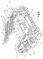
- eine perspektivische Ansicht zweier aneinandergereihter Kettenglieder einer Energieführungskette mit teilweise nach oben verschwenkten Rahmenstegen;
- Fig. 1b
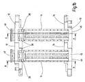
- eine Draufsicht auf die Kettenglieder gemäß Fig. 1a;
- Fig. 1c
- einen Schnitt entlang der Linie A-A gemäß Fig. 1b;
- Fig. 1d
- einen Schnitt entlang der Linie B-B gemäß Fig. 1b und
- Fig. 2a, 2b
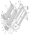
- zwei perspektivische Ansichten der Kettenglieder gemäß Fig. 1a mit einseitig entfernten Seitengliedern.
- Fig. 1a
- a perspective view of two juxtaposed chain links of a power transmission chain with partially upwardly pivoted frame webs;
- Fig. 1b
- a plan view of the chain links according to Fig. 1a;
- Fig. 1c
- a section along the line AA of FIG. 1b;
- Fig. 1d
- a section along the line BB of FIG. 1b and
- Fig. 2a, 2b
- two perspective views of the chain links of FIG. 1a with side members removed on one side.
Die in den Abbildungen dargestellten Kettenglieder 10 für eine Energieführungskette weisen jeweils zwei Seitenglieder 12, 13 sowie die Seitenglieder 12, 13 paarweise miteinander verbindende obere und untere Rahmenstege 14, 16 auf. Die Seitenglieder 12, 13 und die Rahmenstege 14, 16 begrenzen einen Führungskanal 17 für Leitungen wie Schläuche und Kabel. Die Rahmenstege 14, 16 sind jeweils an zwei gegenüberliegenden Endseiten 18, 19 lösbar an den Seitengliedern-12, 13 befestigt. Die Rahmenstege 14, 16 sind als Spritzgussteile einstückig aus Kunststoff gefertigt. Sie bestehen aus einer Vielzahl von identischen Abschnitten, die in einer sich zwischen den Endseiten 18, 19 erstreckenden Längsrichtung aneinander anschließen. An der dem Führungskanal 17 zugewandten Innenseite 22 weisen die Rahmenstege 14, 16 in jedem Abschnitt zwei einander gegenüberliegende, zu ihren Längsseiten hin offene Ausnehmungen 24 auf. Die Ausnehmungen 24 sind arkadenförmig und schließen jeweils mit einem im Querschnitt halbkreisförmigen Bogen ab. Zwischen den Ausnehmungen 24 eines jeden Abschnitts 20 erstreckt sich an der Innenseite 22 der Rahmenstege 14, 16 eine plane Innenfläche 26 zwischen den beiden Endseiten 18, 19. An der der Innenseite 22 gegenüberliegenden Außenseite 28 weisen die Rahmenstege 14, 16 in jedem ihrer Abschnitte 20 vier Anlageflächen 30 auf, die als Teile von Zylindermantelflächen ausgebildet sind. Die Anlageflächen 30 jedes Abschnitts 20 sind im Abstand zueinander angeordnet, wobei sich zwischen ihnen in Längsrichtung der Rahmenstege 14, 16 verlaufende Verstärkungsrippen 32 erstrecken. Die beiden äußeren, an die Längsseiten der Rahmenstege 14, 16 angrenzenden Anlageflächen 30 weisen dabei einen größeren Radius auf als die beiden inneren Anlageflächen 30, die halbe Zylindermantelflächen sind.The chain links 10 shown in the figures for an energy guide chain each have two
An den einander zugewandten Innenseiten 34 der Seitenglieder 12, 13 sind in diese Absätze 36 eingeformt, die die Endseiten 18, 19 der Rahmenstege 14, 16 aufnehmen. In jedem der Absätze 36 sind zwei Zapfen 38 angeformt, die einen runden Querschnitt aufweisen, sowie eine gemeinsame, in Längsrichtung der Energieführungskette verlaufende Mittelachse. Die Zapfen 38 sind in den Ausnehmungen 24 der die Endseiten 18, 19 bildenden Abschnitte der Rahmenstege 14, 16 aufgenommen. Durch die halbrunde, komplementär zur Außenkontur der Zapfen 38 ausgebildete Innenkontur der Ausnehmungen 24 sind die Rahmenstege 14, 16 gegenüber den Seitengliedern 12, 13 verschwenkbar auf den Zapfen 38 gelagert, wobei die Mittelachse der Zapfen 38 die Schwenkachse bildet.At the mutually facing
Zur Fixierung der Rahmenstege 14, 16 an den Seitengliedern 12, 13 werden Befestigungselemente 40 verwendet, die einstückig als Spritzgussteile aus Kunststoff hergestellt sind. Die Befestigungselemente 40 weisen eine Trägerplatte 42 sowie vier an der Trägerplatte 42 angeformte Halteelemente 44 auf. An den Außenseiten 46 der Seitenglieder 12, 13 sind Vertiefungen 48 eingeformt, in die die Befestigungselemente 40 zum Befestigen der Rahmenstege 14, 16 eingesetzt werden. In jeder Vertiefung 48 erstrecken sich vier Durchbrüche 50 von der Außenseite 46 zur Innenseite 34 der Seitenglieder 12, 13. Durch die Durchbrüche 50 greifen die Halteelemente 44 durch und übergreifen die Rahmenstege 14, 16 an deren Außenseite 28. Dabei kommt jedes der Halteelemente 44 mit einer Haltefläche 52 an einer Anlagefläche 30 zur Anlage. Die Halteflächen 52 weisen dabei denselben Krümmungsradius auf wie die Anlageflächen 30, an denen sie anliegen. Sie erstrecken sich jedoch maximal über den halben Umfang der Anlageflächen 30. An jeder der Trägerplatten 42 ist zudem ein Rasthaken 54 angeformt, der zur Fixierung des Befestigungselements 40 am Seitenglied 12, 13 in eine Rastausnehmung 56 in der Vertiefung 48 eingeführt und verrastet wird.For fixing the
Wenn die Befestigung eines der Rahmenstege 14, 16 an einer seiner Endseiten 18 durch Herausziehen eines der Befestigungselemente 40 gelöst wird, kann der Rahmensteg um die Schwenkachse an seiner gegenüberliegenden Endseite 19 nach oben bzw. nach unten geklappt werden, wie in Fig. 1a bis 1d dargestellt. Beim Verschwenken des Rahmenstegs 14, 16 gegenüber dem Seitenglied 13, an dem er befestigt ist, gleiten die Halteflächen 52 über die komplementären Anlageflächen 30. Indem sich die Halteflächen 52 maximal über den halben Umfang der Anlageflächen 30 erstrecken, kann der Rahmensteg 14, 16 um mindestens 90° um die Schwenkachse verschwenkt werden, so dass der Führungskanal 17 zugänglich gemacht wird.If the attachment of one of the
Es versteht sich von selbst, dass die Zahl der Halteelemente 44 pro Befestigungselement 40 sowie die Zahl der Anlageflächen 30 pro Abschnitt 20 der Rahmenstege 14, 16 nicht vier betragen muß.It goes without saying that the number of holding
Die Erfindung betrifft ein Kettenglied für eine Energieführungskette mit zwei Seitengliedern 12, 13 und mit mindestens einem die Seitenglieder 12, 13 miteinander verbindenden Rahmensteg 14, 16, der an seinen einander gegenüberliegenden Endseiten 18, 19 an je einem der Seitenglieder 12, 13 befestigt ist. Erfindungsgemäß ist vorgesehen, dass der mindestens eine Rahmensteg 14, 16 an beiden Seitengliedern 12, 13 mittels eines abnehmbaren Befestigungselements 40 lösbar befestigt ist und bei Lösen der Befestigung an seiner einen Endseite 18 um eine Schwenkachse bezüglich des Seitenglieds 13 verschwenkbar ist, an dem seine andere Endseite 19 befestigt ist.The invention relates to a chain link for a power transmission chain with two
Claims (20)
Applications Claiming Priority (1)
| Application Number | Priority Date | Filing Date | Title |
|---|---|---|---|
| DE200510013430 DE102005013430A1 (en) | 2005-03-21 | 2005-03-21 | Chain link for an energy chain |
Publications (2)
| Publication Number | Publication Date |
|---|---|
| EP1705401A2 true EP1705401A2 (en) | 2006-09-27 |
| EP1705401A3 EP1705401A3 (en) | 2007-01-17 |
Family
ID=36596798
Family Applications (1)
| Application Number | Title | Priority Date | Filing Date |
|---|---|---|---|
| EP06005393A Withdrawn EP1705401A3 (en) | 2005-03-21 | 2006-03-16 | Chain link for a supporting chain for energy carriers |
Country Status (2)
| Country | Link |
|---|---|
| EP (1) | EP1705401A3 (en) |
| DE (1) | DE102005013430A1 (en) |
Families Citing this family (5)
| Publication number | Priority date | Publication date | Assignee | Title |
|---|---|---|---|---|
| DE102015014064A1 (en) | 2015-11-02 | 2017-05-04 | Murrplastik Systemtechnik Gmbh | assembly tool |
| DE102016000864A1 (en) | 2016-01-28 | 2017-08-03 | Murrplastik Systemtechnik Gmbh | Power supply chain |
| DE102017110940A1 (en) | 2017-05-19 | 2018-11-22 | Murrplastik Systemtechnik Gmbh | Power supply chain |
| DE102019101825A1 (en) | 2019-01-25 | 2020-07-30 | Murrplastik Systemtechnik Gmbh | Chain link for an energy chain |
| DE102020106046A1 (en) | 2020-03-05 | 2021-09-09 | Murrplastik Systemtechnik Gmbh | Chain link for an energy chain |
Family Cites Families (14)
| Publication number | Priority date | Publication date | Assignee | Title |
|---|---|---|---|---|
| DE3318365A1 (en) * | 1983-05-20 | 1984-11-22 | Kabelschlepp Gmbh, 5900 Siegen | POWER SUPPLY CHAIN |
| DE3531066A1 (en) * | 1985-08-30 | 1987-03-12 | Igus Gmbh | ENERGY FEED CHAIN |
| DE3812559C1 (en) * | 1988-04-15 | 1989-11-02 | Ansgar 4000 Duesseldorf De Klein | Self-supporting energy-supply chain which can bend on one side |
| DE3928236C1 (en) * | 1989-08-26 | 1990-10-25 | Kabelschlepp Gmbh, 5900 Siegen, De | |
| DE4105653A1 (en) * | 1991-02-22 | 1992-09-03 | Kabelschlepp Gmbh | POWER SUPPLY CHAIN |
| JP3356659B2 (en) * | 1996-10-16 | 2002-12-16 | 株式会社椿本チエイン | Cable drag chain |
| DE19645403A1 (en) * | 1996-11-04 | 1998-05-07 | Kabelschlepp Gmbh | Chain link and energy chain with lockable crossbar |
| DE19703410A1 (en) * | 1997-01-30 | 1998-08-06 | Kabelschlepp Gmbh | Chain link with insertable dividers |
| DE29701598U1 (en) * | 1997-01-31 | 1998-05-28 | Murrplastik Gmbh System Techni | Locking bracket for chain links in an energy chain |
| DE19740967A1 (en) * | 1997-09-17 | 1999-04-01 | Kabelschlepp Gmbh | Guide element and guide device for guiding lines with rotatable contact bodies |
| DE19826749A1 (en) * | 1998-06-16 | 1999-12-23 | Murrplastik Systemtechnik Gmbh | Chain link for energy chains |
| DE19948926B4 (en) * | 1998-12-15 | 2009-06-04 | Kabelschlepp Gmbh | Chain link of an energy chain |
| DE10050316B9 (en) * | 2000-10-10 | 2005-06-30 | B+N Bergbautechnik Gmbh | Energy guiding chain for guiding cables, hoses or the like |
| DE102004017742A1 (en) * | 2004-04-10 | 2005-11-03 | Ekd Gelenkrohr Gmbh | Chain for support of electrical power cables has links with hinged top cross members to allow installation of cable |
-
2005
- 2005-03-21 DE DE200510013430 patent/DE102005013430A1/en not_active Ceased
-
2006
- 2006-03-16 EP EP06005393A patent/EP1705401A3/en not_active Withdrawn
Non-Patent Citations (1)
| Title |
|---|
| None |
Also Published As
| Publication number | Publication date |
|---|---|
| EP1705401A3 (en) | 2007-01-17 |
| DE102005013430A1 (en) | 2006-09-28 |
Similar Documents
| Publication | Publication Date | Title |
|---|---|---|
| EP2694840B1 (en) | Cable drag chain | |
| EP1108157B1 (en) | Energy guide chain for guiding lines comprising chain links which can move in three dimensions | |
| EP0384153B1 (en) | Supporting chain for energy carrier | |
| DE19541928C1 (en) | Energy chain | |
| EP0956465B1 (en) | Chain link with insertable separating pins | |
| WO2010029090A1 (en) | Chain link for an energy guiding chain | |
| DE19919076A1 (en) | Energy chain | |
| EP2981737B1 (en) | Energy guiding chain | |
| DE19647322A1 (en) | Chain link made of different materials and process for its production | |
| WO2005108820A1 (en) | Chain link for a power transmission chain, and power transmission chain having an expanded useful cross section | |
| EP3253994B1 (en) | Chain link and handling chain having a chain link | |
| EP1705401A2 (en) | Chain link for a supporting chain for energy carriers | |
| DE102005061775A1 (en) | Chain link with a locking device | |
| EP2321553B1 (en) | Chain link for an energy guiding chain | |
| WO2000063600A1 (en) | Collar band | |
| EP3434933B1 (en) | Partition | |
| DE19502681A1 (en) | Strain relief and fastener | |
| EP1676050A1 (en) | Link plate, chain link, energy guiding chain, and intermediate piece for an energy guiding chain, provided with locking means coupled by torsion for connecting a flight to a link plate | |
| EP1816373A2 (en) | Supporting chain for energy carriers | |
| DE19948926A1 (en) | Chain link for power conducting chain, has two side plates spaced opposite chain and cross web connecting plates together with closing web | |
| DE19740896C2 (en) | Chain link with swivel bar | |
| DE202008008358U1 (en) | Chain link with swivel crossbar | |
| DE19957021A1 (en) | Energy supply unit has chain links linked together, pivoting towards central axis, bearer arrangements on at least some links, linkage axes of adjacent links mutually offset by 90 degrees | |
| DE102020106046A1 (en) | Chain link for an energy chain | |
| DE102019108707A1 (en) | Cantilever |
Legal Events
| Date | Code | Title | Description |
|---|---|---|---|
| PUAI | Public reference made under article 153(3) epc to a published international application that has entered the european phase |
Free format text: ORIGINAL CODE: 0009012 |
|
| AK | Designated contracting states |
Kind code of ref document: A2 Designated state(s): AT BE BG CH CY CZ DE DK EE ES FI FR GB GR HU IE IS IT LI LT LU LV MC NL PL PT RO SE SI SK TR |
|
| AX | Request for extension of the european patent |
Extension state: AL BA HR MK YU |
|
| PUAL | Search report despatched |
Free format text: ORIGINAL CODE: 0009013 |
|
| AK | Designated contracting states |
Kind code of ref document: A3 Designated state(s): AT BE BG CH CY CZ DE DK EE ES FI FR GB GR HU IE IS IT LI LT LU LV MC NL PL PT RO SE SI SK TR |
|
| AX | Request for extension of the european patent |
Extension state: AL BA HR MK YU |
|
| AKX | Designation fees paid | ||
| STAA | Information on the status of an ep patent application or granted ep patent |
Free format text: STATUS: THE APPLICATION IS DEEMED TO BE WITHDRAWN |
|
| 18D | Application deemed to be withdrawn |
Effective date: 20070718 |
|
| REG | Reference to a national code |
Ref country code: DE Ref legal event code: 8566 |