EP0956465B1 - Chain link with insertable separating pins - Google Patents
Chain link with insertable separating pins Download PDFInfo
- Publication number
- EP0956465B1 EP0956465B1 EP98905120A EP98905120A EP0956465B1 EP 0956465 B1 EP0956465 B1 EP 0956465B1 EP 98905120 A EP98905120 A EP 98905120A EP 98905120 A EP98905120 A EP 98905120A EP 0956465 B1 EP0956465 B1 EP 0956465B1
- Authority
- EP
- European Patent Office
- Prior art keywords
- chain link
- link member
- plate
- member according
- chain
- Prior art date
- Legal status (The legal status is an assumption and is not a legal conclusion. Google has not performed a legal analysis and makes no representation as to the accuracy of the status listed.)
- Expired - Lifetime
Links
Images

Classifications
-
- F—MECHANICAL ENGINEERING; LIGHTING; HEATING; WEAPONS; BLASTING
- F16—ENGINEERING ELEMENTS AND UNITS; GENERAL MEASURES FOR PRODUCING AND MAINTAINING EFFECTIVE FUNCTIONING OF MACHINES OR INSTALLATIONS; THERMAL INSULATION IN GENERAL
- F16G—BELTS, CABLES, OR ROPES, PREDOMINANTLY USED FOR DRIVING PURPOSES; CHAINS; FITTINGS PREDOMINANTLY USED THEREFOR
- F16G13/00—Chains
- F16G13/12—Hauling- or hoisting-chains so called ornamental chains
- F16G13/16—Hauling- or hoisting-chains so called ornamental chains with arrangements for holding electric cables, hoses, or the like
-
- H—ELECTRICITY
- H02—GENERATION; CONVERSION OR DISTRIBUTION OF ELECTRIC POWER
- H02G—INSTALLATION OF ELECTRIC CABLES OR LINES, OR OF COMBINED OPTICAL AND ELECTRIC CABLES OR LINES
- H02G11/00—Arrangements of electric cables or lines between relatively-movable parts
- H02G11/006—Arrangements of electric cables or lines between relatively-movable parts using extensible carrier for the cable, e.g. self-coiling spring
Definitions
- the object of the invention relates to a chain link, in particular a Chain link of an energy chain, with the features of the generic term of claim 1 and an energy chain.
- the energy supply chain is at one End at a fixed point and at the other end with the moving ones Connected consumers.
- the energy chain is articulated with each other connected chain links built.
- a chain link has one Recording room on. Form the receiving spaces of the individual chain links a channel in which the cables can be laid.
- the recording room is by two spaced apart, oppositely arranged Chain links as well as a plate and a traverse limited. The plate and the crossbar is connected to each link plate.
- the utility model G 91 02 121.9 is an energy chain for routing cables from a fixed connection to a movable one Consumers known in the receiving space of the link plates is divided by dividers and rungs. Every divider is between two spaced apart, oppositely positioned Trusses arranged. To fix each divider to the Trusses each divider has a U-shaped at the top and bottom Bracket that surrounds the crossbar.
- Another embodiment of a chain link with dividers and Sprouts for dividing the receiving space is by DE 37 09 953 C2 known.
- additional components are necessary through which the dividers are fixed on the crossbars.
- an additional divider without U-shaped ends necessary, which has a fitting rib, which in a fitting groove of a link plate intervenes, such a separator being necessary for each chain link, so that the dividers arranged in the middle area of the link plates by the arranged between the dividers and connected to them Rungs are fixed.
- a U-shaped chain link is known, which Chain links, which are connected to each other by a plate.
- the recesses formed in the plate can be inserted are.
- DE 34 08 912 C1 is a plastic chain link Energy chain with two spaced apart, each other opposite link plates, which are connected to a plate, are known.
- the link plates and the plate are made in one piece.
- the A crossbar can be connected to chain links.
- the chain link also has at least one separable web connectable to at least the plate, the Plate at least one substantially parallel to a link plate extending groove, which extends only over a partial length of the plate and the separating web on at least one end section is at least one to the groove has correspondingly trained engagement.
- the present invention is based on the object specify a chain link in which a subdivision of the receiving space is possible, the chain link should be inexpensive to manufacture.
- Another object of the invention is the simplest possible one Specify the position fixation of a separator at a chain link.
- Another object of the invention is to provide an energy chain that is inexpensive to manufacture.
- the link plates and the Plate form a one-piece component.
- the link plates and the plate are manufactured in a single manufacturing step. This will create a Achieved more economical production of the link plates and the plate.
- the Chain link made of plastic according to the invention is also characterized by that the plate is at least one substantially parallel to a link plate extending profile groove and the separating web on at least one separating section at least one trained corresponding to the profile groove Has engagement that in the longitudinal direction of the link plate in the profile groove can be inserted. Through the profile groove in the plate and the engagement on Divider becomes a positive connection between the divider and the plate reached.
- the profile groove in cross-section T-shaped or dovetail-shaped is trained.
- the engagement has a cross section of the Profile groove corresponding cross-section.
- the profile groove and engagement be in their longitudinal directions rejuvenate.
- This configuration also ensures that the Separator takes a defined position within the recording room.
- the tapered profile groove and Intervention can also be a frictional connection of the separator with the Plate can be reached.
- the profile groove and the engagement conical.
- the Profile groove in a central section of the longitudinal extension of the link plates is trained.
- the plate preferably has a substantially transverse to Bead extending in the longitudinal direction of the link plates, in which the profile groove is trained. This configuration saves material the design of the chain link achieved because the plate only a minimum Can have thickness.
- the bead is preferably on the plate molded on, in particular the plate is formed in one piece with the bead.
- the profile groove be only over a partial length of the plate or the bead extends.
- the engagement extends only over a partial width of the separating web.
- the engagement is preferably at most as long as the profile groove.
- the plate be essentially one shoulder extending transversely to the longitudinal extent of the link plate and the separator has a projection at a distance from the engagement, which for Attachment to the shoulder.
- the shoulder is preferably formed by the bead, whereby a economical production of the chain link is retained.
- the section of the separating web lying between the engagement and the projection can be brought into contact with the bead.
- This configuration will a large-scale application of force from the separator into the bead or plate reached, whereby the separator is also suitable with rungs to be, creating a further subdivision of the recording space is made possible.
- the receptacle is preferably formed by at least two spaced-apart opposite each other, in the longitudinal direction of the link plates extending longitudinal ribs formed.
- Each shot is additionally divided by two spaced from each other, opposite each other, in the longitudinal direction of the link plates extending transverse ribs.
- the traverse is given a high degree of rigidity, so that the crossbeam does not bend even under load.
- the cross member of the chain link is designed so that the Cross ribs are provided for all recordings, being between the cross ribs the longitudinal ribs are formed.
- the Plate and the crossbar are lid-shaped, so that the receiving space is protected from external influences.
- an energy chain proposed with articulated chain links at least a chain link of the energy chain according to one of claims 1 to 21 is formed.
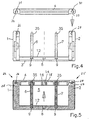
- Fig. 1 shows an embodiment of a chain link made of plastic in a top view in partial section.
- the chain link has two of them spaced-apart, opposite link plates 1, 2.
- the link plates 1, 2 are connected to a plate 3.
- the link plates 1, 2 and the plate 3 form a substantially U-shaped chain link.
- the chain link 1 points at an end region and on that facing away from the link plate 2 Surface on a hinge pin 19.
- an articulated bore 22 is formed opposite the end region.
- the Hinge bore 22 is designed so that a hinge pin 19 of an adjacent one Chain link in the joint bore 22 is pivotable.
- the chain link 2 is designed according to the link plate 1.
- the chain link 2 has one Articulated bolt 20 and an articulated bore 21.
- the plate 3 has a profile groove 8, which is essentially parallel to the link plates 1, 2 extends.
- the profile groove 8 has a substantially T-shaped cross section, like this 7 can be seen in particular. 1 is only one Profile groove 8 formed in the plate 3.
- the plate 3 can have a plurality of profile grooves 8. The number of Profile grooves 8 are essentially based on the requirement profile a chain link.
- the profile groove 8 serves to define a separating web 6, 7 as in the Fig. 3 is shown.
- the separating web 6, 7 has one at an end section Engagement 9, the cross section of which is designed in accordance with the profile groove 8.
- the cross section of the engagement 9 is substantially T-shaped, like this 7 can be seen in particular.
- the separator 6, 7 has an engagement that is only a Section of the separating web extends to.
- the section of the intervention 9 corresponds essentially the length of the profile groove 8. Spaced to the Engagement 9, the separating web is provided with a projection 11.
- the separator 6, 7 can be inserted into the profile groove 8. 6 is the separator 6 connected to the plate 3 is shown. The intervention 9 of the Separator 6 is held in the profile groove 8. The projection 11 of the separator 6 rests on a shoulder 10.
- the shoulder 10 is on the plate 3 educated.
- the shoulder 10 extends essentially transversely to the longitudinal direction the link plates, as can be seen from FIG. 1.
- the Shoulder 10 is formed by a bead 12.
- the bead 12 is with the Plate 3 formed in one piece. It preferably extends over the total width of the plate 3.
- the profile groove 8 and the engagement 9 in the longitudinal direction.
- the profile groove 8 and Engagement 9 conical.
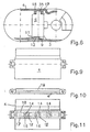
- the cross member 4 of the chain link is in the illustrated embodiment lid-shaped.
- the traverse 4 is with the chain link and 2 releasably connected by a hinge-like joint 24, 25.
- Each link plate has a pivot pin 26, 27, which is in a free working 28, 29 of the link plate 1 or 2 is formed.
- the lid-shaped cross member 4 has recesses 30, 31, which each have an undercut 32, 33.
- the traverse 4 can completely from the link plates 1, 2 or only from the plate 1 or 2 can be released and then around the pivot pin 26 or 27 be pivoted.
- the cross member 4 has receptacles 14, in each of which the engagement 9 opposite end region 35 of the separating web 6 or 7 at least partially protrudes.
- the end region 35 of the separating web 6, 7 is tab-shaped educated.
- Each receptacle 14 is separated by two mutually opposite, in the longitudinal direction of the link plates 1, 2nd extending longitudinal ribs 15, 16 formed.
- each receptacle 14 by two spaced from each other opposite, transversely to the longitudinal direction of the link plates 1, 2 extending transverse ribs 17, 18 limited.
- the transverse ribs 17, 18 are for All recordings 14 are provided, the between the transverse ribs 17, 18 Longitudinal ribs 15, 16 are formed, as is shown in particular in FIG. 11 can be seen.
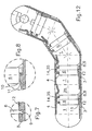
- the traverse shown in Figures 9 to 10 is essentially lid-shaped. This also applies to plate 3. If there are several composite chain links to form an energy chain, as described in 12 is the receiving channel of the energy chain essentially completed. A through the dividers 6, 7 Subdivision of the receiving space 5 of the chain link or the channel Longitudinal energy chain. A subdivision of the recording room 5 or the receiving channel 34 can also take place in the transverse direction. For this the dividers can be connected with rungs, not shown.
Description
Der Gegenstand der Erfindung betrifft ein Kettenglied, insbesondere ein
Kettenglied einer Energieführungskette, mit den Merkmalen des Oberbegriffs
des Anspruchs 1 sowie eine Energieführungskette.The object of the invention relates to a chain link, in particular a
Chain link of an energy chain, with the features of the generic term
of
Leitungen, die zu einem beweglichen Verbraucher führen, werden in sogenannten Energieführungsketten verlegt. Die Energieführungskette ist an einem Ende an einem Festpunkt und mit ihrem anderen Ende mit den beweglichen Verbraucher verbunden. Die Energieführungskette ist aus gelenkig miteinander verbundenen Kettengliedern aufgebaut. Ein Kettenglied weist einen Aufnahmeraum auf. Die Aufnahmeräume der einzelnen Kettenglieder bilden einen Kanal, in dem die Leitungen verlegbar sind. Der Aufnahmeraum ist durch zwei voneinander beabstandet, einander gegenüberliegend angeordnete Kettenlaschen sowie eine Platte und eine Traverse begrenzt. Die Platte und die Traverse ist mit jeder Kettenlasche verbunden.Lines that lead to a mobile consumer are in so-called Energy chains laid. The energy supply chain is at one End at a fixed point and at the other end with the moving ones Connected consumers. The energy chain is articulated with each other connected chain links built. A chain link has one Recording room on. Form the receiving spaces of the individual chain links a channel in which the cables can be laid. The recording room is by two spaced apart, oppositely arranged Chain links as well as a plate and a traverse limited. The plate and the crossbar is connected to each link plate.
Zur Vermeidung von Schäden an den Leitungen, die im Kanal der Energieführungskette verlegbar sind, ist es bekannt, den Querschnitt des Kanals und somit auch den Aufnahmeraum eines jeden Kettengliedes zu unterteilen. Durch das Gebrauchsmuster G 91 02 121.9 ist eine Energieführungskette zum Führen von Leitungen von einem ortsfesten Anschluß zu einem beweglichen Verbraucher bekannt, bei der der Aufnahmeraum der Kettenlaschen durch Trennstege und Sprossen unterteilt ist. Jeder Trennsteg ist zwischen zwei voneinander beabstandeten, einander gegenüberliegend positionierten Traversen angeordnet. Zur Festlegung eines jeden Trennstegs an den Traversen weist jeder Trennsteg am oberen und unteren Ende eine U-förmige Halterung, die die Traverse umgreift, auf. Desweiteren weist jeder Trennsteg zwischen den Schenkeln U-förmigen Halterung einen Stift auf, der in eine entsprechende Bohrung der Traversen eingegreift, so daß der Trennsteg nicht in Längsrichtung der Traversen verschiebbar ist. Die Traverse ist als ein gesondertes Bauteil des Kettengliedes ausgebildet.To avoid damage to the cables in the channel of the energy chain can be installed, it is known the cross section of the channel and to subdivide the receiving space of each chain link. The utility model G 91 02 121.9 is an energy chain for routing cables from a fixed connection to a movable one Consumers known in the receiving space of the link plates is divided by dividers and rungs. Every divider is between two spaced apart, oppositely positioned Trusses arranged. To fix each divider to the Trusses each divider has a U-shaped at the top and bottom Bracket that surrounds the crossbar. Furthermore, everyone points Separator between the legs of a U-shaped bracket on a pin engages in a corresponding bore of the cross members, so that the separating web cannot be moved in the longitudinal direction of the crossbeams. The traverse is formed as a separate component of the chain link.
Eine weitere Ausführungsform eines Kettengliedes mit Trennstegen und - sprossen zur Unterteilung des Aufnahmeraumes ist durch die DE 37 09 953 C2 bekannt. Bei dieser Ausführungsform sind zusätzliche Bauteile notwendig, durch die die Trennstege auf den Traversen fixiert werden. So ist beispielsweise ein zusätzlicher Trennsteg ohne U-förmig ausgebildeten Enden notwendig, der eine Paßrippe aufweist, die in eine Paßnut einer Kettenlasche eingreift, wobei ein solcher Trennsteg für jede Kettenlasche notwendig ist, so daß die im mittleren Bereich der Kettenlaschen angeordneten Trennstege durch die zwischen den Trennstegen angeordneten und mit diesen verbundenen Sprossen fixiert werden.Another embodiment of a chain link with dividers and Sprouts for dividing the receiving space is by DE 37 09 953 C2 known. In this embodiment, additional components are necessary through which the dividers are fixed on the crossbars. For example an additional divider without U-shaped ends necessary, which has a fitting rib, which in a fitting groove of a link plate intervenes, such a separator being necessary for each chain link, so that the dividers arranged in the middle area of the link plates by the arranged between the dividers and connected to them Rungs are fixed.
Desweiteren ist ein U-förmig ausgebildetes Kettenglied bekannt, welches Kettenlaschen, die durch eine Platte miteinander verbunden sind, aufweist. Zur Unterteilung des durch das Kettenglied gebildeten Aufnahmeraums sind Trennstege vorgesehen, die in der Platte ausgebildete Ausnehmungen einsteckbar sind.Furthermore, a U-shaped chain link is known, which Chain links, which are connected to each other by a plate. To subdivide the receiving space formed by the chain link Separators provided, the recesses formed in the plate can be inserted are.
Durch die DE 34 08 912 C1 ist ein Kettenglied aus Kunststoff einer Energieführungskette mit zwei voneinander beabstandeten, einander gegenüberliegenden Kettenlaschen, die mit einer Platte verbunden sind, bekannt. Die Kettenlaschen und die Platte sind einstückig ausgebildet. Mit den Kettenlaschen ist eine Traverse verbindbar. Das Kettenglied weist desweiteren wenigstens einen mit wenigstens der Platte verbindbaren Trennsteg auf, wobei die Platte wenigstens einer sich im wesentlichen parallel zu einer Kettenlasche erstreckende Nut, die sich lediglich über eine Teillänge der Platte erstreckt und der Trennsteg an wenigstens einem Endabschnitt wenigstens einen zur Nut korrespondierend ausgebildeten Eingriff aufweist.DE 34 08 912 C1 is a plastic chain link Energy chain with two spaced apart, each other opposite link plates, which are connected to a plate, are known. The link plates and the plate are made in one piece. With the A crossbar can be connected to chain links. The chain link also has at least one separable web connectable to at least the plate, the Plate at least one substantially parallel to a link plate extending groove, which extends only over a partial length of the plate and the separating web on at least one end section is at least one to the groove has correspondingly trained engagement.
Problematisch bei dem durch die DE 34 08 912 C1 bekannten Ausgestaltung des
Kettengliedes ist, daß der Trennsteg aufgrund der relativ geringen Einstecktiefe
des Endabschnitts in die Nut um eine im wesentlichen quer zur Längsachse des
Trennstegs und der Nut verlaufende Achse verdrehbar ist, so daß eine stabile
Verbindung zwischen dem Trennsteg und der Platte nicht zuverlässig ist.
Insbesondere bei einer Energieführungskette, die aus solchen Kettengliedern.
aufgebaut ist, besteht manchmal die Notwendigkeit, die in der Kette geführten
Leitungen auszutauschen. Während des Austauschs der Leitungen kann der
Trennsteg so belastet werden, daß diese aus der Nut herausgedreht wird. Ein
nachträgliches Einbringen des Trennstegs in die Nut ist mit einem nicht
unerheblichen Montageaufwand verbunden.Problematic in the embodiment of the known from
Die Ausbildung der Nut im Kettenglied aus Kunststoff erfolgt bei der aus der DE
34 08 912 C1 bekannten Ausgestaltung des Kettengliedes auch relativ auffällig,
da entsprechende Formwerkzeuge mit entsprechenden Einsätzen notwendig sind.The formation of the groove in the chain link made of plastic takes place in the
Hiervon ausgehend liegt der vorliegenden Erfindung die Aufgabe zugrunde, ein Kettenglied anzugeben, bei dem eine Unterteilung des Aufnahmeraums möglich ist, wobei das Kettenglied kostengünstig herstellbar sein soll. Ein weiteres Ziel der Erfindung ist es eine möglichst einfache Möglichkeit einer Lagefixierung eines Trennsteges bei einem Kettenglied anzugeben. Ein weiteres Ziel der Erfindung ist es eine Energieführungskette anzugeben, die kostengünstig herstellbar ist. Proceeding from this, the present invention is based on the object specify a chain link in which a subdivision of the receiving space is possible, the chain link should be inexpensive to manufacture. On Another object of the invention is the simplest possible one Specify the position fixation of a separator at a chain link. On Another object of the invention is to provide an energy chain that is inexpensive to manufacture.
Diese Aufgabe wird erfindungsgemäß durch ein Kettenglied mit den Merkmalen
des Anspruchs 1 und einer Energieführungskette mit den Merkmalen
des Anspruchs 20 gelöst. Vorteilhafte Weitergestaltungen sind Gegenstand der
Unteransprüche.This object is achieved by a chain link with the features
of
Bei dem erfindungsgemäßen Kettenglied bilden die Kettenlaschen und die Platte ein einstückiges Bauteil bilden. Die Kettenlaschen und die Platte werden in einem einzigen Herstellungsschritt hergestellt. Hierdurch wird eine wirtschaftlichere Herstellung der Kettenlaschen und der Platte erreicht. Das erfindungsgemäße Kettenglied aus Kunststoff zeichnet sich auch dadurch aus, daß die Platte wenigstens eine sich im wesentlichen parallel zu einer Kettenlasche erstreckende Profilnut und der Trennsteg an wenigstens einem Trennabschnitt mindestens einen zur Profilnut korrespondierend ausgebildeten Eingriff aufweist, der in Längsrichtung der Kettenlasche in die Profilnut einschiebbar ist. Durch die Profilnut in der Platte und den Eingriff am Trennsteg wird eine formschlüssige Verbindung zwischen dem Trennsteg und der Platte erreicht. Die Herstellung eines solchen Kettengliedes wird wesentlich vereinfacht, da aufgrund der Ausgestaltung der Kettenlaschen und der Platte sowie der in der Platte ausgebildeten Profilnut das notwendige Werkzeug einfacher gestaltet werden kann, da eine Entformung des Bauteils im Spritzwerkzeug vereinfacht wird. Zum Entformen des Bauteils ist es ausreichend, daß Spritzwerkzeug in zwei Ebenen aufzufahren.In the chain link according to the invention, the link plates and the Plate form a one-piece component. The link plates and the plate are manufactured in a single manufacturing step. This will create a Achieved more economical production of the link plates and the plate. The Chain link made of plastic according to the invention is also characterized by that the plate is at least one substantially parallel to a link plate extending profile groove and the separating web on at least one separating section at least one trained corresponding to the profile groove Has engagement that in the longitudinal direction of the link plate in the profile groove can be inserted. Through the profile groove in the plate and the engagement on Divider becomes a positive connection between the divider and the plate reached. The production of such a chain link becomes essential simplified because of the design of the link plates and the Plate and the profile groove formed in the plate are the necessary tools can be made easier, since a demolding of the component in the Injection mold is simplified. To demold the component, it is sufficient to open that injection mold in two levels.
Bei dem erfindungsgemäßen Kettenglied aus Kunststoff ist durch die Ausgestaltung der Profilnut und des Eingriffs ein Verschieben des Trennstegs quer zur Längserstreckung der Kettenlaschen nicht notwendig, so daß auf zusätzliche Bauteile, wie dies im Stand der Technik notwendig ist, verzichtet werden kann. In the chain link made of plastic is due to the design the profile groove and the engagement a transverse movement of the separator not necessary for the longitudinal extension of the link plates, so that additional Components, as is necessary in the prior art, are dispensed with can be.
Zur formschlüssigen Verbindung des Trennstegs mit der Platte wird vorgeschlagen, daß die Profilnut im Querschnitt T-förmig oder schwalbenschwanzförmig ausgebildet ist. Der Eingriff weist einen dem Querschnitt der Profilnut entsprechenden Querschnitt auf.For the positive connection of the separating web to the plate, it is proposed that the profile groove in cross-section T-shaped or dovetail-shaped is trained. The engagement has a cross section of the Profile groove corresponding cross-section.
Zur Vereinfachung des Einschiebens des Eingriffs in die Profilnut wird vorgeschlagen, daß die Profilnut und der Eingriff sich in ihren Längsrichtungen verjüngen. Durch diese Ausgestaltung wird auch erreicht, daß der Trennsteg eine definierte Lage innerhalb des Aufnahmeraums einnimmt. Durch entsprechende Ausgestaltung der sich verjüngenden Profilnut und des Eingriffs kann auch eine reibschlüssige Verbindung des Trennstegs mit der Platte erreicht werden. Vorzugsweise ist die Profilnut und der Eingriff konisch ausgebildet.To simplify the insertion of the engagement in the profile groove suggested that the profile groove and engagement be in their longitudinal directions rejuvenate. This configuration also ensures that the Separator takes a defined position within the recording room. By appropriate design of the tapered profile groove and Intervention can also be a frictional connection of the separator with the Plate can be reached. Preferably, the profile groove and the engagement conical.
Nach einem weiteren vorteilhaften Gedanken wird vorgeschlagen, daß die Profilnut in einen mittleren Abschnitt der Längserstreckung der Kettenlaschen ausgebildet ist. Die Platte weist vorzugsweise eine im wesentlichen quer zur Längsrichtung der Kettenlaschen verlaufende Wulst auf, in der die Profilnut ausgebildet ist. Durch diese Ausgestaltung wird eine Materialersparnis bei der Ausgestaltung des Kettengliedes erreicht, da die Platte nur eine mindestnotwendige Dicke haben kann. Vorzugsweise ist die Wulst an der Platte angeformt, insbesondere ist die Platte mit der Wulst einstückig ausgebildet.After a further advantageous thought, it is proposed that the Profile groove in a central section of the longitudinal extension of the link plates is trained. The plate preferably has a substantially transverse to Bead extending in the longitudinal direction of the link plates, in which the profile groove is trained. This configuration saves material the design of the chain link achieved because the plate only a minimum Can have thickness. The bead is preferably on the plate molded on, in particular the plate is formed in one piece with the bead.
Nach einer weiteren vorteilhaften Ausgestaltung des Kettengliedes wird vorgeschlagen, daß die Profilnut sich nur über eine Teillänge der Platte bzw. der Wulst erstreckt. Zur Fixierung des Trennstegs ist es ausreichend, wenn der Eingriff sich nur über eine Teilbreite des Trennstegs erstreckt. Vorzugsweise ist der Eingriff höchstens so lang wie die Profilnut. According to a further advantageous embodiment of the chain link suggested that the profile groove be only over a partial length of the plate or the bead extends. To fix the separator, it is sufficient to if the engagement extends only over a partial width of the separating web. The engagement is preferably at most as long as the profile groove.
Während des Betriebes einer Energieführungskette, die aus Kettengliedern aufgebaut ist, kann es durch Erschütterungen und Vibrationen der Energieführungskette zu einer Lösung des Trennstegs von der Platte kommen. Um dies zu verhindern, wird vorgeschlagen, daß die Platte eine sich im wesentlichen quer zur Längserstreckung der Kettenlasche erstreckende Schulter und der Trennsteg mit Abstand zum Eingriff einen Vorsprung aufweist, der zur Anlage an die Schulter bringbar ist. Durch die Kombination-Schulter/Vorsprung wird eine Sicherung des Trennstegs erreicht, so daß der Trennsteg auch durch Vibrationen oder Erschütterungen sich nicht von der Platte löst. Vorzugsweise ist die Schulter durch die Wulst ausgebildet, wodurch eine wirtschaftliche Herstellung des Kettengliedes erhalten bleibt.During the operation of an energy chain consisting of chain links built up, it can be caused by shocks and vibrations in the energy chain come to a separation of the separator from the plate. Around To prevent this, it is suggested that the plate be essentially one shoulder extending transversely to the longitudinal extent of the link plate and the separator has a projection at a distance from the engagement, which for Attachment to the shoulder. Through the combination shoulder / lead the separator is secured, so that the separator also does not come off the plate due to vibrations or shocks. The shoulder is preferably formed by the bead, whereby a economical production of the chain link is retained.
Nach einem weiteren vorteilhaften Gedanken wird vorgschlagen, daß der zwischen dem Eingriff und dem Vorsprung liegende Abschnitt des Trennstegs zur Anlage an die Wulst bringbar ist. Durch diese Ausgestaltung wird eine großflächige Krafteinleitung vom Trennsteg in die Wulst bzw. Platte erreicht, wodurch der Trennsteg auch dazu geeignet ist mit Sprossen versehen zu werden, wodurch eine weitere Unterteilung des Aufnahmeraums ermöglicht wird.After a further advantageous thought, it is proposed that the section of the separating web lying between the engagement and the projection can be brought into contact with the bead. This configuration will a large-scale application of force from the separator into the bead or plate reached, whereby the separator is also suitable with rungs to be, creating a further subdivision of the recording space is made possible.
Energieführungsketten werden in der Praxis üblicherweise so angeordnet, daß die Kettenlaschen im wesentlichen senkrecht zu einer Auflage für die Energieführungskette verlaufen. Bei einer um 90° gedrehten Anordnung einer Energieführungskette befinden sich die Kettenlaschen in einer zu einer Auflage im wesentlichen parallelen Ebene. Um sicherzustellen, daß das erfindungsgemäße Kettenglied auch für solch eine Anordnung einer Energieführungskette verwendbar ist, wird vorgeschlagen, daß die Traverse Aufnahmen aufweist, in die jeweils ein dem Eingriff gegenüberliegender Endbereich des Trennstegs wenigstens teilweise hineinragt. Durch diese Ausgestaltung stützt sich jeder Trennsteg mit seinem einen Ende an der Traverse und mit seinem anderen Ende an der Platte ab. Die Traverse weist vorzugsweise eine der Profilnuten entsprechende Anzahl von Aufnahmen auf. Dies ist nicht zwingend notwendig. Bevorzugt ist eine Traverse, die eine höhere Anzahl an Aufnahmen aufweist als die Anzahl der Profilnuten. Hierdurch kann eine Traverse für Kettenglieder mit unterschiedlicher Anzahl von Profilnuten verwendet werden. Es versteht sich, daß die Aufnahmen im montierten Zustand der Traverse fluchtend über den Profilnuten liegen.In practice, energy supply chains are usually arranged in such a way that the link plates essentially perpendicular to a support for the energy chain run. With an arrangement rotated by 90 ° The chain links are in one to one Edition essentially parallel plane. To make sure that Chain link according to the invention also for such an arrangement of an energy chain is usable, it is proposed that the traverse shots has, in each case an end region opposite the engagement of the separator at least partially protrudes. Through this configuration each separator is supported with one end on the crossbar and with its other end on the plate. The cross member preferably has one of the profile grooves corresponding number of shots. This is not mandatory. A traverse is preferred, the higher one Number of recordings has as the number of profile grooves. hereby can be a traverse for chain links with different numbers of Profile grooves are used. It is understood that the recordings in the assembled state of the crossbar should be flush with the profile grooves.
Vorzugsweise ist die Aufnahme durch wenigstens zwei voneinander beabstandeten, einander gegenüberliegende, sich in Längsrichtung der Kettenlaschen erstreckende Längsrippen gebildet. Jede Aufnahme ist zusätzlich durch zwei voneinander beabstandete, einander gegenüberliegende, sich in Längsrichtung der Kettenlaschen erstreckende Querrippen gebildet. Durch diese Ausgestaltung der Aufnahmen wird der Traverse eine hohe Eigensteifigkeit verliehen, so daß die Traverse auch im Belastungszustand keine Durchbiegung erfährt. Vorzugsweise ist die Traverse des Kettengliedes so ausgebildet, daß die Querrippen für alle Aufnahmen vorgesehen sind, wobei zwischen den Querrippen die Längsrippen ausgebildet sind.The receptacle is preferably formed by at least two spaced-apart opposite each other, in the longitudinal direction of the link plates extending longitudinal ribs formed. Each shot is additionally divided by two spaced from each other, opposite each other, in the longitudinal direction of the link plates extending transverse ribs. Through this configuration the traverse is given a high degree of rigidity, so that the crossbeam does not bend even under load. Preferably, the cross member of the chain link is designed so that the Cross ribs are provided for all recordings, being between the cross ribs the longitudinal ribs are formed.
Nach einem weiteren vorteilhaften Gedanken wird vorgeschlagen, daß die Platte und die Traverse deckelförmig ausgebildet sind, so daß der Aufnahmeraum vor äußeren Einflüssen geschützt wird.After a further advantageous thought, it is proposed that the Plate and the crossbar are lid-shaped, so that the receiving space is protected from external influences.
Gemäß einem weiteren erfinderischen Gedankens wird eine Energieführungskette
mit gelenkig verbundenen Kettengliedern vorgeschlagen, wobei wenigstens
ein Kettenglied der Energieführungskette nach einem der Ansprüche 1
bis 21 ausgebildet ist. According to a further inventive idea, an energy chain
proposed with articulated chain links, at least
a chain link of the energy chain according to one of
Weitere Einzelheiten und Vorteile eines Kettengliedes sowie einer Energieführungskette werden anhand der in der Zeichnung dargestellten Ausführungsbeispiele erläutert. Es zeigen:
- Fig. 1
- ein Kettenglied in einer Draufsicht,
- Fig. 2
- das Kettenglied im Schnitt der Vorderansicht,
- Fig. 3
- einen Trennsteg,
- Fig. 4
- das Kettenglied in einer Seitenansicht mit Trennstegen und einer Traverse,
- Fig. 5
- das Kettenglied in einer Seitenansicht mit montierten Traverse,
- Fig. 6
- das Kettenglied mit Trennsteg und Traverse im Schnitt in einer Vorderansicht,
- Fig. 7
- vergrößert eine Profilnut in der Platte und einen Trennsteg in einer Seitenansicht und im Schnitt,
- Fig. 8
- vergrößert einen Trennsteg in einer Vorderansicht im Schnitt,
- Fig. 9
- eine Draufsicht einer als Deckel ausgebildeten Traverse,
- Fig. 10
- eine Vorderansicht der Traverse,
- Fig. 11
- eine Unteransicht der Traverse,
- Fig. 12
- einen Abschnitt einer Energieführungskette im Längsschnitt.
- Fig. 1
- a chain link in a plan view,
- Fig. 2
- the chain link in section of the front view,
- Fig. 3
- a separator,
- Fig. 4
- the chain link in a side view with dividers and a crossbar,
- Fig. 5
- the chain link in a side view with mounted crossbar,
- Fig. 6
- the chain link with separator and crossbar in section in a front view,
- Fig. 7
- enlarges a profile groove in the plate and a separator in a side view and in section,
- Fig. 8
- enlarges a separator in a front view in section,
- Fig. 9
- a plan view of a cross member designed as a cover,
- Fig. 10
- a front view of the traverse,
- Fig. 11
- a bottom view of the traverse,
- Fig. 12
- a section of an energy chain in longitudinal section.
Fig. 1 zeigt ein Ausführungsbeispiel eines Kettengliedes aus Kunststoff in
einer Draufsicht im Teilschnitt. Das Kettenglied weist zwei voneinander
beabstandete, einander gegenüberliegende Kettenlaschen 1, 2 auf. Die Kettenlaschen
1, 2 sind mit einer Platte 3 verbunden. Die Kettenlaschen 1, 2 und
die Platte 3 bilden ein im wesentlichen U-förmiges Kettenglied. Die Kettenlasche
1 weist an einem Endbereich und auf der der Kettenlasche 2 abgewandten
Fläche einen Gelenkbolzen 19 auf. In dem dem Gelenkbolzen 19
gegenüberliegenden Endbereich ist eine Gelenkbohrung 22 ausgebildet. Die
Gelenkbohrung 22 ist so gestaltet, daß ein Gelenkbolzen 19 eines benachbarten
Kettengliedes in der Gelenkbohrung 22 verschwenkbar ist. Zur
Begrenzung eines Verschwenkwinkels benachbarter Kettenglieder weist jede
Kettenlasche 1, 2 eine Vertiefung 23 auf, die im Bereich der Gelenkbohrung
22 bzw. 21 der Kettenlasche 2 ausgebildet ist. Die Kettenlasche 2 ist
entsprechend der Kettenlasche 1 ausgebildet. Die Kettenlasche 2 weist einen
Gelenkbolzen 20 sowie eine Gelenkbohrung 21 auf.Fig. 1 shows an embodiment of a chain link made of plastic in
a top view in partial section. The chain link has two of them
spaced-apart,
Die Platte 3 weist eine Profilnut 8 auf, die sich im wesentlichen parallel zu
den Kettenlaschen 1, 2 erstreckt. In dem dargestellten Ausführungsbeispiel
hat die Profilnut 8 einen im wesentlichen T-förmigen Querschnitt, wie dies
insbesondere aus der Fig. 7 entnehmbar ist. In der Fig. 1 ist lediglich eine
Profilnut 8 in der Platte 3 ausgebildet. Wie aus der Fig. 4 bzw. 5 ersichtlich
ist, kann die Platte 3 mehrere Profilnuten 8 aufweisen. Die Anzahl der
Profilnuten 8 richtet sich im wesentlichen nach dem Anforderungsprofil an
ein Kettenglied.The
Die Profilnut 8 dient zur Festlegung eines Trennstegs 6, 7 wie er in der
Fig. 3 dargestellt ist. Der Trennsteg 6, 7 weist an einem Endabschnitt einen
Eingriff 9, dessen Querschnitt entsprechend der Profilnut 8 ausgebildet ist.
Der Querschnitt des Eingriffs 9 ist im wesentlichen T-förmig, wie dies
insbesondere aus der Fig. 7 ersichtlich ist. In dem darstellten Ausführungsbeispiel
weist der Trennsteg 6, 7 einen Eingriff, der sich lediglich über eine
Teilbreite des Trennstegs erstreckt auf. Die Teilbreite des Eingriffs 9 entspricht
im wesentlichen der Länge der Profilnut 8. Beabstandet zu dem
Eingriff 9 ist der Trennsteg mit einem Vorsprung 11 versehen.The
Der Trennsteg 6, 7 ist in die Profilnut 8 einschiebbar. In der Fig. 6 ist
der mit der Platte 3 verbundene Trennsteg 6 dargestellt. Der Eingriff 9 des
Trennstegs 6 ist in der Profilnut 8 gehaltert. Der Vorsprung 11 des Trennstegs
6 liegt an einer Schulter 10 an. Die Schulter 10 ist an der Platte 3
ausgebildet. Die Schulter 10 erstreckt sich im wesentlichen quer zur Längsrichtung
der Kettenlaschen, wie dies aus der Fig. 1 ersichtlich ist. Die
Schulter 10 ist durch eine Wulst 12 gebildet. Die Wulst 12 ist mit der
Platte 3 einstückig ausgebildet. Sie erstreckt sich vorzugsweise über die
gesamte Breite der Platte 3.The
Zwischen dem Eingriff 9 und dem Eingriff 11 des Trennstegs 6 ist ein
Abschnitt 13 ausgebildet, der im montierten Zustand des Trennstegs 6 an
der Wulst 12 anliegt.Between the
In dem dargestellten Ausführungsbeispiel verjüngt sich die Profilnut 8 und
der Eingriff 9 in Längsrichtung. Vorzugsweise ist die Profilnut 8 und der
Eingriff 9 konisch ausgebildet.In the illustrated embodiment, the
Die Traverse 4 des Kettengliedes ist in dem dargestellten Ausführungsbeispiel
deckelförmig ausgebildet. Die Traverse 4 ist mit der Kettenlasche und
2 lösbar durch ein scharnierartig ausgebildetes Gelenk 24, 25 verbunden.
Jede Kettenlasche weist einen Gelenkzapfen 26, 27 auf, der in einer Freiarbeitung
28, 29 der Kettenlasche 1 bzw. 2 ausgebildet ist. The
Die deckelförmig ausgebildete Traverse 4 weist Ausnehmungen 30, 31 auf,
die jeweils eine Hinterschneidung 32, 33 aufweisen. Die Traverse 4 kann
vollständig von den Kettenlaschen 1, 2 oder lediglich von der Lasche 1
bzw. 2 gelöst werden und anschließend um den Gelenkzapfen 26 bzw. 27
verschwenkt werden.The lid-shaped
Die Traverse 4 weist Aufnahmen 14 auf, in die jeweils ein dem Eingriff 9
gegenüberliegende Endbereich 35 des Trennstegs 6 bzw. 7 wenigstens
teilweise hineinragt. Der Endbereich 35 des Trennstegs 6, 7 ist laschenförmig
ausgebildet. Jede Aufnahme 14 ist durch zwei voneinander beabstandete,
einander gegenüberliegende, sich in Längsrichtung der Kettenlaschen 1, 2
erstreckende Längsrippen 15, 16 gebildet. In dem dargestellten Ausführungsbeispiel
ist jede Aufnahme 14 durch zwei voneinander beabstandete, einander
gegenüberliegende, sich quer zur Längsrichtung der Kettenlaschen 1, 2
erstreckende Querrippen 17, 18 begrenzt. Die Querrippen 17, 18 sind für
alle Aufnahmen 14 vorgesehen, wobei zwischen den Querrippen 17, 18 die
Längsrippen 15, 16 ausgebildet sind, wie dies insbesondere aus der Fig. 11
ersichtlich ist.The
Die in den Figuren 9 bis 10 dargestellte Traverse ist im wesentlichen
deckelförmig ausgebildet. Dies gilt auch für die Platte 3. Bei mehreren
zusammengesetzten Kettengliedern zu einer Energieführungskette, wie sie in
der Fig. 12 dargestellt ist, ist der Aufnahmekanal der Energieführungskette
im wesentlichen abgeschlossen. Durch die Trennstege 6, 7 erfolgt eine
Unterteilung des Aufnahmeraums 5 des Kettengliedes bzw. des Kanals der
Energieführungskette in Längsrichtung. Eine Unterteilung des Aufnahmeraums
5 bzw. des Aufnahmekanals 34 kann auch in Querrichtung erfolgen. Hierzu
können die Trennstege mit nicht dargestellten Sprossen verbunden werden. The traverse shown in Figures 9 to 10 is essentially
lid-shaped. This also applies to
- 1, 21, 2
- Kettenlaschelink plate
- 33
- Platteplate
- 44
- Traversetraverse
- 55
- Aufnahmeraumaccommodation space
- 6, 76, 7
- Trennstegdivider
- 88th
- Profilnutprofile groove
- 99
- Eingriffintervention
- 1010
- Schultershoulder
- 1111
- Vorsprunghead Start
- 1212
- Wulstbead
- 1313
- Abschnittsection
- 1414
- Aufnahmeadmission
- 15, 1615, 16
- Längsrippelongitudinal rib
- 17, 1817, 18
- Querrippetransverse rib
- 19, 2019, 20
- Gelenkbolzenhinge pins
- 21, 2221, 22
- Gelenkbohrungpivotal hole
- 2323
- Vertiefungdeepening
- 24, 2524, 25
- Gelenkjoint
- 26, 2726, 27
- Gelenkzapfenpivot pin
- 28, 2928, 29
- FreiarbeitungFree elaboration
- 30, 3130, 31
- Ausnehmungrecess
- 32, 3332, 33
- Hinterschneidungundercut
- 3434
- Aufnahmekanalreceiving channel
- 3535
- Endbereichend
Claims (20)
- A chain link member of plastic material, in particular a chain link member of an energy guide chain, comprising two spaced-apart, mutually oppositely disposed link plates (1, 2), which are connected to a plate (3), wherein the link plates (1, 2) and the plate (3) are of a one-piece configuration, a transverse portion (4) which can be connected to the link plates (1, 2), and with at least one dividing web (6, 7) which can be connected to at least the plate (3), wherein the plate (3) has at least one groove extending substantially parallel to a link plate (1, 2), the groove extending only over a partial length of the plate (5) and the dividing web (6, 7) having at at least one end portion (9) at least one engagement portion (9) which is of a configuration corresponding to the groove (8), characterized in that the groove is of a configuration of a shaped groove (8), that the end portion (9) is insertable into the shaped groove (8), that the engagement portion (9) extends only over a partial width of the dividing web (6, 7) and that the plate (3) has a shoulder (10) extending substantially transversely with respect to the longitudinal direction of the link plate (1, 2) and the dividing web (6, 7) comprises a projection (11) that is spaced to the engagement portion (9), wherein the projection (11) can be brought to bear against the shoulder (10).
- A chain link member according to claim 1, characterized in that the shaped groove (8) is of a T-shaped configuration in cross-section.
- A chain link member according to claim 1, characterized in that the shaped groove (8) is of a dovetail-shaped configuration in cross-section.
- A chain link member according to claim 1, 2 or 3, characterized in that the shaped groove (8) and the engagement portion (9) narrow in their longitudinal directions.
- A chain link member according to claim 4, characterized in that the shaped groove (8) and the engagement portion (9) are of a conical configuration.
- A chain link member according to one of claims 1 to 5, characterized in that the shaped groove (8) is formed in a central portion of the longitudinal extent of the link plates (1, 2).
- A chain link member according to one of claims 1 to 6, characterized in that the plate (3) has a ridge (12) which extends substantially transversely to the longitudinal direction of the link plates (1, 2) and in which the shaped groove (8) is provided.
- A chain link member according to claim 7, characterized in that the ridge (12) is formed on the plate (3).
- A chain link member according to claim 8, characterized in that the plate (3) is formed integrally with the ridge (12).
- A chain link member according to one of claims 7 to 9, characterized in that the shaped groove (8) extends only over a partial width of the ridge (12).
- A chain link member according to one of claims 1 to 10, characterized in that the engagement portion (9) is at most as long as the shaped groove (8).
- A chain link member according to one of claims 1 to 11, characterized in that the shoulder (10) is formed by a ridge (12).
- A chain link member according to claim 12, characterized in that the portion (13) of the dividing web (6, 7), which is between the engagement portion (9) and the projection(11), can be brought to bear against the ridge (12).
- A chain link member according to one of claims 1 to 13, characterized in that the transverse portion (4) is provided with recesses (14) into which there at least partially projects a respective end region (35) of the dividing web (6, 7) which end region (35) is opposite to the engagement portion (9).
- A chain link member according to claim 14, characterized in that the end region (15) of the dividing web (6, 7) is of a tongue-like configuration.
- A chain link member according to claim 14 or 15, characterized in that the recess (14) is formed at least by two spaced-apart, mutually oppositely disposed longitudinal ribs (15, 16) extending in the longitudinal direction of the link plates (1, 2).
- A chain link member according to claim 16, characterized in that each recess (14) is additionally formed by two spaced-apart, mutually oppositely disposed transverse ribs (17, 18) extending transversally with respect to the longitudinal direction of the link plates (1, 2).
- A chain link member according to claim 16, characterized in that the transverse ribs (17, 18) are provided for all recesses (14), the longitudinal ribs (15, 16) being provided between the transverse ribs (17, 18).
- A chain link member according to one of claims 1 to 18, characterized in that the plate (3) and the transverse portion (4) are formed as a cover.
- An energy guide chain with hingedly connected chain link members, wherein at least one chain link member is of a configuration according to one of the claims 1 to 19.
Applications Claiming Priority (3)
| Application Number | Priority Date | Filing Date | Title |
|---|---|---|---|
| DE19703410A DE19703410A1 (en) | 1997-01-30 | 1997-01-30 | Chain link with insertable dividers |
| DE19703410 | 1997-01-30 | ||
| PCT/EP1998/000293 WO1998034050A1 (en) | 1997-01-30 | 1998-01-20 | Chain link with insertable separating pins |
Publications (2)
| Publication Number | Publication Date |
|---|---|
| EP0956465A1 EP0956465A1 (en) | 1999-11-17 |
| EP0956465B1 true EP0956465B1 (en) | 2002-04-17 |
Family
ID=7818805
Family Applications (1)
| Application Number | Title | Priority Date | Filing Date |
|---|---|---|---|
| EP98905120A Expired - Lifetime EP0956465B1 (en) | 1997-01-30 | 1998-01-20 | Chain link with insertable separating pins |
Country Status (6)
| Country | Link |
|---|---|
| US (1) | US6176072B1 (en) |
| EP (1) | EP0956465B1 (en) |
| JP (1) | JP2001509869A (en) |
| DE (2) | DE19703410A1 (en) |
| TW (1) | TW470828B (en) |
| WO (1) | WO1998034050A1 (en) |
Cited By (1)
| Publication number | Priority date | Publication date | Assignee | Title |
|---|---|---|---|---|
| DE102005013430A1 (en) * | 2005-03-21 | 2006-09-28 | Murrplastik Systemtechnik Gmbh | Chain link for an energy chain |
Families Citing this family (23)
| Publication number | Priority date | Publication date | Assignee | Title |
|---|---|---|---|---|
| DE19919076C2 (en) * | 1999-04-19 | 2001-08-30 | Igus Gmbh | Energy chain |
| EP1074764A3 (en) * | 1999-08-06 | 2001-04-11 | Jacques Zindel | Device for guiding and supporting a trailing chain |
| JP3716987B2 (en) * | 2002-11-28 | 2005-11-16 | 株式会社椿本チエイン | Cable protection guide device |
| JP3717168B2 (en) * | 2003-04-28 | 2005-11-16 | 株式会社椿本チエイン | Cable protection guide device |
| JP3716990B2 (en) * | 2003-05-12 | 2005-11-16 | 株式会社椿本チエイン | Cable protection guide device |
| DE10346653A1 (en) | 2003-10-08 | 2005-06-09 | Kabelschlepp Gmbh | Chain link, chain link and energy guiding chain, as well as intermediate piece for an energy guiding chain, with torsion-coupled locking means for connecting crosspiece and link plate |
| JP4121446B2 (en) * | 2003-11-17 | 2008-07-23 | 株式会社椿本チエイン | Cable protection guide device |
| DE102005061777A1 (en) * | 2005-12-23 | 2007-06-28 | Kabelschlepp Gmbh | Chain link for energy transmission chain, has transverse bar and clips arranged at distance to each other, where transverse bar is pin-jointed with one clip, and pin-joint is multi-axis pin-joint and ball-and-socket joint connection |
| DE102005061775A1 (en) | 2005-12-23 | 2007-08-02 | Kabelschlepp Gmbh | Chain link with a locking device |
| JP4420934B2 (en) * | 2007-03-29 | 2010-02-24 | 株式会社椿本チエイン | Cable protection guide device |
| JP4338746B2 (en) * | 2007-04-27 | 2009-10-07 | 株式会社椿本チエイン | Cable protection guide device |
| JP4722207B2 (en) * | 2009-08-06 | 2011-07-13 | 株式会社椿本チエイン | Cable protection guide device |
| JP5393509B2 (en) * | 2010-01-29 | 2014-01-22 | 富士通フロンテック株式会社 | Cable holder |
| DE202010006220U1 (en) * | 2010-04-29 | 2011-09-07 | Igus Gmbh | Endless circulating link belt with power supply |
| US8622481B2 (en) * | 2011-01-25 | 2014-01-07 | Joy Mm Delaware, Inc. | Fiber optic cable protection in a mining system |
| DE202011004762U1 (en) * | 2011-04-04 | 2011-09-07 | Igus Gmbh | Power supply chain |
| JP5350445B2 (en) * | 2011-08-03 | 2013-11-27 | 株式会社椿本チエイン | Cable protection guide device |
| US8733077B2 (en) * | 2012-10-04 | 2014-05-27 | Hewlett-Packard Development Company, L.P. | Transmission line guide chains and dividers for transmission line guide chains |
| WO2016171725A1 (en) * | 2015-04-24 | 2016-10-27 | Hewlett Packard Enterprise Development Lp | Cable track |
| DE202017100200U1 (en) * | 2017-01-16 | 2017-01-25 | Igus Gmbh | Divider for energy supply chains |
| DE102017117089A1 (en) * | 2017-07-28 | 2019-01-31 | Murrplastik Systemtechnik Gmbh | divider |
| DE102019121206A1 (en) * | 2019-08-06 | 2021-02-11 | Peter Knupfer | LINE MANAGEMENT CHANNEL |
| CN110454548A (en) * | 2019-09-06 | 2019-11-15 | 无锡德斯普拖链技术有限公司 | A kind of drag chain link structure |
Family Cites Families (15)
| Publication number | Priority date | Publication date | Assignee | Title |
|---|---|---|---|---|
| DE2255283C3 (en) * | 1972-11-11 | 1975-06-05 | Kabelschlepp Gmbh, 5900 Siegen | Energy chain |
| DE3408912C1 (en) * | 1984-03-10 | 1985-08-14 | Murr-Plastik Gmbh, 7155 Oppenweiler | Energy-carrying chain |
| DE3414412C1 (en) * | 1984-04-17 | 1987-11-12 | Kabelschlepp Gmbh, 5900 Siegen | Energy supply chain |
| US4590961A (en) * | 1985-08-16 | 1986-05-27 | Cooper Industries, Inc. | Modular rolling conductor support |
| DE3709953A1 (en) * | 1987-03-26 | 1988-10-13 | Igus Gmbh | CHAIN LINK FOR ENERGY FEED CHAIN |
| JPH0210851Y2 (en) * | 1987-10-09 | 1990-03-16 | ||
| JPH02186146A (en) * | 1989-01-09 | 1990-07-20 | Oriental Chain Kogyo Kk | Closed type cable support chain |
| DE3928234C1 (en) * | 1989-08-26 | 1991-04-11 | Kabelschlepp Gmbh, 5900 Siegen, De | |
| JPH0743008B2 (en) * | 1990-08-10 | 1995-05-15 | 株式会社椿本チエイン | Partition structure inside the cable drag chain |
| DE4105652A1 (en) * | 1991-02-22 | 1992-09-03 | Kabelschlepp Gmbh | POWER SUPPLY CHAIN |
| DE9102121U1 (en) | 1991-02-22 | 1991-05-16 | Kabelschlepp Gmbh, 5900 Siegen, De | |
| JP2507194Y2 (en) * | 1991-07-31 | 1996-08-14 | 株式会社椿本チエイン | Internal partition structure of cable drag chain |
| JPH0573339U (en) * | 1992-03-11 | 1993-10-08 | 大和電業株式会社 | Open cable drag chain |
| DE4413303C1 (en) * | 1994-04-18 | 1995-05-24 | Kabelschlepp Gmbh | Traverse for energy supply chain |
| US5724803A (en) * | 1995-05-04 | 1998-03-10 | Hubbell Incorporated | Power supply chain with roller bar carrier |
-
1997
- 1997-01-30 DE DE19703410A patent/DE19703410A1/en not_active Withdrawn
- 1997-12-11 TW TW086118720A patent/TW470828B/en not_active IP Right Cessation
-
1998
- 1998-01-20 JP JP53249998A patent/JP2001509869A/en not_active Ceased
- 1998-01-20 EP EP98905120A patent/EP0956465B1/en not_active Expired - Lifetime
- 1998-01-20 DE DE59803846T patent/DE59803846D1/en not_active Expired - Lifetime
- 1998-01-20 US US09/355,608 patent/US6176072B1/en not_active Expired - Fee Related
- 1998-01-20 WO PCT/EP1998/000293 patent/WO1998034050A1/en active IP Right Grant
Cited By (1)
| Publication number | Priority date | Publication date | Assignee | Title |
|---|---|---|---|---|
| DE102005013430A1 (en) * | 2005-03-21 | 2006-09-28 | Murrplastik Systemtechnik Gmbh | Chain link for an energy chain |
Also Published As
| Publication number | Publication date |
|---|---|
| TW470828B (en) | 2002-01-01 |
| DE19703410A1 (en) | 1998-08-06 |
| DE59803846D1 (en) | 2002-05-23 |
| EP0956465A1 (en) | 1999-11-17 |
| JP2001509869A (en) | 2001-07-24 |
| US6176072B1 (en) | 2001-01-23 |
| WO1998034050A1 (en) | 1998-08-06 |
Similar Documents
| Publication | Publication Date | Title |
|---|---|---|
| EP0956465B1 (en) | Chain link with insertable separating pins | |
| EP1108157B1 (en) | Energy guide chain for guiding lines comprising chain links which can move in three dimensions | |
| EP0966624B1 (en) | Collapsible line protection element | |
| EP0384153B1 (en) | Supporting chain for energy carrier | |
| EP0756674B1 (en) | Tie-bar for power conducting chain | |
| EP1175571B1 (en) | Cable carrier chain | |
| EP0499809B1 (en) | Supporting chain for energy carriers | |
| EP1963711B1 (en) | Reduced noise drag chain system | |
| DE19512088A1 (en) | Energy chain | |
| WO2010029090A1 (en) | Chain link for an energy guiding chain | |
| EP0963523B1 (en) | Energy supply chain with extra tough core chain links and method for the production of one such chain link | |
| DE3408912C1 (en) | Energy-carrying chain | |
| EP1611927A1 (en) | Snowglide board | |
| DE102005061775A1 (en) | Chain link with a locking device | |
| DE3227276A1 (en) | JOINT CHAIN, ESPECIALLY ORNAMENTAL JOINT CHAIN AND DEVICE FOR PRODUCING THE SAME IN THE MOLDING PROCESS | |
| DE10004015A1 (en) | Spring element and method for constructing a spring element | |
| EP3036806B1 (en) | Cable duct and method for producing a three-dimensional cable duct | |
| EP1705401A2 (en) | Chain link for a supporting chain for energy carriers | |
| DE19547215A1 (en) | Shelf for links of "energy guidance chain" | |
| DE3909797C1 (en) | Energy supply chain for receiving cables and/or lines | |
| EP0941428B1 (en) | Component kit for a chain link adaptable to different uses | |
| DE19707689C1 (en) | Cable bridging section with at least one cable-channel | |
| DE19740896C2 (en) | Chain link with swivel bar | |
| EP2927162A1 (en) | Module member for a conveyor belt, and conveyor belt made of module members that are flexibly connected to each other and method for producing a module member | |
| DE19915026C2 (en) | tire chain |
Legal Events
| Date | Code | Title | Description |
|---|---|---|---|
| PUAI | Public reference made under article 153(3) epc to a published international application that has entered the european phase |
Free format text: ORIGINAL CODE: 0009012 |
|
| 17P | Request for examination filed |
Effective date: 19990730 |
|
| AK | Designated contracting states |
Kind code of ref document: A1 Designated state(s): DE FR IT |
|
| 17Q | First examination report despatched |
Effective date: 20000518 |
|
| GRAG | Despatch of communication of intention to grant |
Free format text: ORIGINAL CODE: EPIDOS AGRA |
|
| GRAG | Despatch of communication of intention to grant |
Free format text: ORIGINAL CODE: EPIDOS AGRA |
|
| GRAH | Despatch of communication of intention to grant a patent |
Free format text: ORIGINAL CODE: EPIDOS IGRA |
|
| GRAH | Despatch of communication of intention to grant a patent |
Free format text: ORIGINAL CODE: EPIDOS IGRA |
|
| GRAA | (expected) grant |
Free format text: ORIGINAL CODE: 0009210 |
|
| AK | Designated contracting states |
Kind code of ref document: B1 Designated state(s): DE FR IT |
|
| PG25 | Lapsed in a contracting state [announced via postgrant information from national office to epo] |
Ref country code: FR Free format text: LAPSE BECAUSE OF FAILURE TO SUBMIT A TRANSLATION OF THE DESCRIPTION OR TO PAY THE FEE WITHIN THE PRESCRIBED TIME-LIMIT Effective date: 20020417 |
|
| REF | Corresponds to: |
Ref document number: 59803846 Country of ref document: DE Date of ref document: 20020523 |
|
| EN | Fr: translation not filed | ||
| PLBE | No opposition filed within time limit |
Free format text: ORIGINAL CODE: 0009261 |
|
| STAA | Information on the status of an ep patent application or granted ep patent |
Free format text: STATUS: NO OPPOSITION FILED WITHIN TIME LIMIT |
|
| 26N | No opposition filed |
Effective date: 20030120 |
|
| PGFP | Annual fee paid to national office [announced via postgrant information from national office to epo] |
Ref country code: IT Payment date: 20060131 Year of fee payment: 9 |
|
| PG25 | Lapsed in a contracting state [announced via postgrant information from national office to epo] |
Ref country code: IT Free format text: LAPSE BECAUSE OF NON-PAYMENT OF DUE FEES Effective date: 20070120 |
|
| PGFP | Annual fee paid to national office [announced via postgrant information from national office to epo] |
Ref country code: DE Payment date: 20140203 Year of fee payment: 17 |
|
| REG | Reference to a national code |
Ref country code: DE Ref legal event code: R119 Ref document number: 59803846 Country of ref document: DE |
|
| PG25 | Lapsed in a contracting state [announced via postgrant information from national office to epo] |
Ref country code: DE Free format text: LAPSE BECAUSE OF NON-PAYMENT OF DUE FEES Effective date: 20150801 |