EP0956465B1 - Kettenglied mit einschiebbaren trennstegen - Google Patents
Kettenglied mit einschiebbaren trennstegen Download PDFInfo
- Publication number
- EP0956465B1 EP0956465B1 EP98905120A EP98905120A EP0956465B1 EP 0956465 B1 EP0956465 B1 EP 0956465B1 EP 98905120 A EP98905120 A EP 98905120A EP 98905120 A EP98905120 A EP 98905120A EP 0956465 B1 EP0956465 B1 EP 0956465B1
- Authority
- EP
- European Patent Office
- Prior art keywords
- chain link
- link member
- plate
- member according
- chain
- Prior art date
- Legal status (The legal status is an assumption and is not a legal conclusion. Google has not performed a legal analysis and makes no representation as to the accuracy of the status listed.)
- Expired - Lifetime
Links
- 239000000463 material Substances 0.000 claims description 2
- 239000011324 bead Substances 0.000 description 11
- 238000004519 manufacturing process Methods 0.000 description 6
- 238000003780 insertion Methods 0.000 description 3
- 230000037431 insertion Effects 0.000 description 3
- 238000002347 injection Methods 0.000 description 2
- 239000007924 injection Substances 0.000 description 2
- 230000035939 shock Effects 0.000 description 2
- 230000004308 accommodation Effects 0.000 description 1
- 230000015572 biosynthetic process Effects 0.000 description 1
- 239000002131 composite material Substances 0.000 description 1
- 230000001419 dependent effect Effects 0.000 description 1
- 238000011161 development Methods 0.000 description 1
- 230000018109 developmental process Effects 0.000 description 1
- 238000009434 installation Methods 0.000 description 1
- 230000000717 retained effect Effects 0.000 description 1
- 238000000926 separation method Methods 0.000 description 1
Images

Classifications
-
- F—MECHANICAL ENGINEERING; LIGHTING; HEATING; WEAPONS; BLASTING
- F16—ENGINEERING ELEMENTS AND UNITS; GENERAL MEASURES FOR PRODUCING AND MAINTAINING EFFECTIVE FUNCTIONING OF MACHINES OR INSTALLATIONS; THERMAL INSULATION IN GENERAL
- F16G—BELTS, CABLES, OR ROPES, PREDOMINANTLY USED FOR DRIVING PURPOSES; CHAINS; FITTINGS PREDOMINANTLY USED THEREFOR
- F16G13/00—Chains
- F16G13/12—Hauling- or hoisting-chains so called ornamental chains
- F16G13/16—Hauling- or hoisting-chains so called ornamental chains with arrangements for holding electric cables, hoses, or the like
-
- H—ELECTRICITY
- H02—GENERATION; CONVERSION OR DISTRIBUTION OF ELECTRIC POWER
- H02G—INSTALLATION OF ELECTRIC CABLES OR LINES, OR OF COMBINED OPTICAL AND ELECTRIC CABLES OR LINES
- H02G11/00—Arrangements of electric cables or lines between relatively-movable parts
- H02G11/006—Arrangements of electric cables or lines between relatively-movable parts using extensible carrier for the cable, e.g. self-coiling spring
Definitions
- the object of the invention relates to a chain link, in particular a Chain link of an energy chain, with the features of the generic term of claim 1 and an energy chain.
- the energy supply chain is at one End at a fixed point and at the other end with the moving ones Connected consumers.
- the energy chain is articulated with each other connected chain links built.
- a chain link has one Recording room on. Form the receiving spaces of the individual chain links a channel in which the cables can be laid.
- the recording room is by two spaced apart, oppositely arranged Chain links as well as a plate and a traverse limited. The plate and the crossbar is connected to each link plate.
- the utility model G 91 02 121.9 is an energy chain for routing cables from a fixed connection to a movable one Consumers known in the receiving space of the link plates is divided by dividers and rungs. Every divider is between two spaced apart, oppositely positioned Trusses arranged. To fix each divider to the Trusses each divider has a U-shaped at the top and bottom Bracket that surrounds the crossbar.
- Another embodiment of a chain link with dividers and Sprouts for dividing the receiving space is by DE 37 09 953 C2 known.
- additional components are necessary through which the dividers are fixed on the crossbars.
- an additional divider without U-shaped ends necessary, which has a fitting rib, which in a fitting groove of a link plate intervenes, such a separator being necessary for each chain link, so that the dividers arranged in the middle area of the link plates by the arranged between the dividers and connected to them Rungs are fixed.
- a U-shaped chain link is known, which Chain links, which are connected to each other by a plate.
- the recesses formed in the plate can be inserted are.
- DE 34 08 912 C1 is a plastic chain link Energy chain with two spaced apart, each other opposite link plates, which are connected to a plate, are known.
- the link plates and the plate are made in one piece.
- the A crossbar can be connected to chain links.
- the chain link also has at least one separable web connectable to at least the plate, the Plate at least one substantially parallel to a link plate extending groove, which extends only over a partial length of the plate and the separating web on at least one end section is at least one to the groove has correspondingly trained engagement.
- the present invention is based on the object specify a chain link in which a subdivision of the receiving space is possible, the chain link should be inexpensive to manufacture.
- Another object of the invention is the simplest possible one Specify the position fixation of a separator at a chain link.
- Another object of the invention is to provide an energy chain that is inexpensive to manufacture.
- the link plates and the Plate form a one-piece component.
- the link plates and the plate are manufactured in a single manufacturing step. This will create a Achieved more economical production of the link plates and the plate.
- the Chain link made of plastic according to the invention is also characterized by that the plate is at least one substantially parallel to a link plate extending profile groove and the separating web on at least one separating section at least one trained corresponding to the profile groove Has engagement that in the longitudinal direction of the link plate in the profile groove can be inserted. Through the profile groove in the plate and the engagement on Divider becomes a positive connection between the divider and the plate reached.
- the profile groove in cross-section T-shaped or dovetail-shaped is trained.
- the engagement has a cross section of the Profile groove corresponding cross-section.
- the profile groove and engagement be in their longitudinal directions rejuvenate.
- This configuration also ensures that the Separator takes a defined position within the recording room.
- the tapered profile groove and Intervention can also be a frictional connection of the separator with the Plate can be reached.
- the profile groove and the engagement conical.
- the Profile groove in a central section of the longitudinal extension of the link plates is trained.
- the plate preferably has a substantially transverse to Bead extending in the longitudinal direction of the link plates, in which the profile groove is trained. This configuration saves material the design of the chain link achieved because the plate only a minimum Can have thickness.
- the bead is preferably on the plate molded on, in particular the plate is formed in one piece with the bead.
- the profile groove be only over a partial length of the plate or the bead extends.
- the engagement extends only over a partial width of the separating web.
- the engagement is preferably at most as long as the profile groove.
- the plate be essentially one shoulder extending transversely to the longitudinal extent of the link plate and the separator has a projection at a distance from the engagement, which for Attachment to the shoulder.
- the shoulder is preferably formed by the bead, whereby a economical production of the chain link is retained.
- the section of the separating web lying between the engagement and the projection can be brought into contact with the bead.
- This configuration will a large-scale application of force from the separator into the bead or plate reached, whereby the separator is also suitable with rungs to be, creating a further subdivision of the recording space is made possible.
- the receptacle is preferably formed by at least two spaced-apart opposite each other, in the longitudinal direction of the link plates extending longitudinal ribs formed.
- Each shot is additionally divided by two spaced from each other, opposite each other, in the longitudinal direction of the link plates extending transverse ribs.
- the traverse is given a high degree of rigidity, so that the crossbeam does not bend even under load.
- the cross member of the chain link is designed so that the Cross ribs are provided for all recordings, being between the cross ribs the longitudinal ribs are formed.
- the Plate and the crossbar are lid-shaped, so that the receiving space is protected from external influences.
- an energy chain proposed with articulated chain links at least a chain link of the energy chain according to one of claims 1 to 21 is formed.
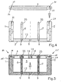
- Fig. 1 shows an embodiment of a chain link made of plastic in a top view in partial section.
- the chain link has two of them spaced-apart, opposite link plates 1, 2.
- the link plates 1, 2 are connected to a plate 3.
- the link plates 1, 2 and the plate 3 form a substantially U-shaped chain link.
- the chain link 1 points at an end region and on that facing away from the link plate 2 Surface on a hinge pin 19.
- an articulated bore 22 is formed opposite the end region.
- the Hinge bore 22 is designed so that a hinge pin 19 of an adjacent one Chain link in the joint bore 22 is pivotable.
- the chain link 2 is designed according to the link plate 1.
- the chain link 2 has one Articulated bolt 20 and an articulated bore 21.
- the plate 3 has a profile groove 8, which is essentially parallel to the link plates 1, 2 extends.
- the profile groove 8 has a substantially T-shaped cross section, like this 7 can be seen in particular. 1 is only one Profile groove 8 formed in the plate 3.
- the plate 3 can have a plurality of profile grooves 8. The number of Profile grooves 8 are essentially based on the requirement profile a chain link.
- the profile groove 8 serves to define a separating web 6, 7 as in the Fig. 3 is shown.
- the separating web 6, 7 has one at an end section Engagement 9, the cross section of which is designed in accordance with the profile groove 8.
- the cross section of the engagement 9 is substantially T-shaped, like this 7 can be seen in particular.
- the separator 6, 7 has an engagement that is only a Section of the separating web extends to.
- the section of the intervention 9 corresponds essentially the length of the profile groove 8. Spaced to the Engagement 9, the separating web is provided with a projection 11.
- the separator 6, 7 can be inserted into the profile groove 8. 6 is the separator 6 connected to the plate 3 is shown. The intervention 9 of the Separator 6 is held in the profile groove 8. The projection 11 of the separator 6 rests on a shoulder 10.
- the shoulder 10 is on the plate 3 educated.
- the shoulder 10 extends essentially transversely to the longitudinal direction the link plates, as can be seen from FIG. 1.
- the Shoulder 10 is formed by a bead 12.
- the bead 12 is with the Plate 3 formed in one piece. It preferably extends over the total width of the plate 3.
- the profile groove 8 and the engagement 9 in the longitudinal direction.
- the profile groove 8 and Engagement 9 conical.
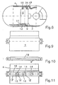
- the cross member 4 of the chain link is in the illustrated embodiment lid-shaped.
- the traverse 4 is with the chain link and 2 releasably connected by a hinge-like joint 24, 25.
- Each link plate has a pivot pin 26, 27, which is in a free working 28, 29 of the link plate 1 or 2 is formed.
- the lid-shaped cross member 4 has recesses 30, 31, which each have an undercut 32, 33.
- the traverse 4 can completely from the link plates 1, 2 or only from the plate 1 or 2 can be released and then around the pivot pin 26 or 27 be pivoted.
- the cross member 4 has receptacles 14, in each of which the engagement 9 opposite end region 35 of the separating web 6 or 7 at least partially protrudes.
- the end region 35 of the separating web 6, 7 is tab-shaped educated.
- Each receptacle 14 is separated by two mutually opposite, in the longitudinal direction of the link plates 1, 2nd extending longitudinal ribs 15, 16 formed.
- each receptacle 14 by two spaced from each other opposite, transversely to the longitudinal direction of the link plates 1, 2 extending transverse ribs 17, 18 limited.
- the transverse ribs 17, 18 are for All recordings 14 are provided, the between the transverse ribs 17, 18 Longitudinal ribs 15, 16 are formed, as is shown in particular in FIG. 11 can be seen.
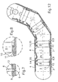
- the traverse shown in Figures 9 to 10 is essentially lid-shaped. This also applies to plate 3. If there are several composite chain links to form an energy chain, as described in 12 is the receiving channel of the energy chain essentially completed. A through the dividers 6, 7 Subdivision of the receiving space 5 of the chain link or the channel Longitudinal energy chain. A subdivision of the recording room 5 or the receiving channel 34 can also take place in the transverse direction. For this the dividers can be connected with rungs, not shown.
Landscapes
- Engineering & Computer Science (AREA)
- General Engineering & Computer Science (AREA)
- Mechanical Engineering (AREA)
- Transmission Devices (AREA)
- Sawing (AREA)
- Chain Conveyers (AREA)
- Electric Cable Arrangement Between Relatively Moving Parts (AREA)
Description
- Fig. 1
- ein Kettenglied in einer Draufsicht,
- Fig. 2
- das Kettenglied im Schnitt der Vorderansicht,
- Fig. 3
- einen Trennsteg,
- Fig. 4
- das Kettenglied in einer Seitenansicht mit Trennstegen und einer Traverse,
- Fig. 5
- das Kettenglied in einer Seitenansicht mit montierten Traverse,
- Fig. 6
- das Kettenglied mit Trennsteg und Traverse im Schnitt in einer Vorderansicht,
- Fig. 7
- vergrößert eine Profilnut in der Platte und einen Trennsteg in einer Seitenansicht und im Schnitt,
- Fig. 8
- vergrößert einen Trennsteg in einer Vorderansicht im Schnitt,
- Fig. 9
- eine Draufsicht einer als Deckel ausgebildeten Traverse,
- Fig. 10
- eine Vorderansicht der Traverse,
- Fig. 11
- eine Unteransicht der Traverse,
- Fig. 12
- einen Abschnitt einer Energieführungskette im Längsschnitt.
- 1, 2
- Kettenlasche
- 3
- Platte
- 4
- Traverse
- 5
- Aufnahmeraum
- 6, 7
- Trennsteg
- 8
- Profilnut
- 9
- Eingriff
- 10
- Schulter
- 11
- Vorsprung
- 12
- Wulst
- 13
- Abschnitt
- 14
- Aufnahme
- 15, 16
- Längsrippe
- 17, 18
- Querrippe
- 19, 20
- Gelenkbolzen
- 21, 22
- Gelenkbohrung
- 23
- Vertiefung
- 24, 25
- Gelenk
- 26, 27
- Gelenkzapfen
- 28, 29
- Freiarbeitung
- 30, 31
- Ausnehmung
- 32, 33
- Hinterschneidung
- 34
- Aufnahmekanal
- 35
- Endbereich
Claims (20)
- Kettenglied aus Kunststoff, insbesondere Kettenglied einer Energieführunaskette, mit zwei voneinander beabstandeten, einander gegenüberliegenden Kettenlaschen (1, 2), die mit einer Platte (3) verbunden sind, wobei die Kettenlaschen (1, 2) und die Platte (3) einstückig ausgebildet sind, einer Traverse (4), die mit den Kettenlaschen (1, 2) verbindbar ist, und mit wenigstens einem mit wenigstens der Platte (3) verbindbaren Trennsteg (6, 7), wobei die Platte (3) wenigstens eine sich im wesentlichen parallel zur einer Kettenlasche (1, 2) erstreckende Nut, die sich lediglich über eine Teillänge der Platte (5) erstreckt und der Trennsteg (6, 7) an wenigstens einem Endabschnitt (9) mindestens einen zur Nut (8) korrespondierend ausgebildeten Eingriff (9) aufweist, dadurch gekennzeichnet, daß die Nut als eine Profilnut (8) ausgebildet ist, daß der Endabschnitt (9) in Längsrichtung der Kettenlaschen (1, 2) in die Profilnut (8) einschiebbar ist, daß der Eingriff (9) sich nur über eine Teilbreite des Trennstegs (6, 7) erstreckt, und daß die Platte (3) eine sich im wesentlichen quer zur Längsrichtung der Kettenlaschen (1, 2) erstreckende Schulter (10) und der Trennsteg (6, 7) mit Abstand zum Eingriff (9) einen Vorsprung (11) aufweist, der zur Anlage an die Schulter (10) bringbar ist.
- Kettenglied nach Anspruch 1, dadurch gekennzeichnet, daß die Profilnut (8) im Querschnitt T-förmig ausgebildet ist.
- Kettenglied nach Anspruch 1, dadurch gekennzeichnet, daß die Profilnut (8) im Querschnitt schwalbenschwanzförmig ausgebildet ist.
- Kettenglied nach Anspruch 1, 2 oder 3, dadurch gekennzeichnet, daß die Profilnut (8) und der Eingriff (9) sich in ihren Längsrichtungen verjüngen.
- Kettenglied nach Anspruch 4, dadurch gekennzeichnet, daß die Profilnut (8) und der Eingriff (9) konisch ausgebildet sind.
- Kettenglied nach einem der Ansprüche 1 bis 5, dadurch gekennzeichnet, daß die Profilnut (8) in einem mittleren Abschnitt der Längserstreckung der Kettenlaschen (1, 2) ausgebildet ist.
- Kettenglied nach einem der Ansprüche 1 bis 6, dadurch gekennzeichnet, die Platte (3) eine im wesentlichen quer zur Längsrichtung der Kettenlaschen (1, 2) verlaufende Wulst (12) aufweist, in der die Profilnut (8) ausgebildet ist.
- Kettenglied nach Anspruch 7, dadurch gekennzeichnet, daß die Wulst (12) an der Platte (3) angeformt ist.
- Kettenglied nach Anspruch 8, dadurch gekennzeichnet, daß die Platte (3) mit der Wulst (12) einstückig ausgebildet ist.
- Kettenglied nach einem der Ansprüche 7 bis 9, dadurch gekennzeichnet, daß die Profilnut (8) sich nur über eine Teillänge der Wulst (12) erstreckt.
- Kettenglied nach einem der Ansprüche 1 bis 10, dadurch gekennzeichnet, daß der Eingriff (9) höchstens so lang ist wie die Profilnut (8).
- Kettenglied nach einem der Ansprüche 1 bis 11, dadurch gekennzeichnet, daß die Schulter (10) durch eine Wulst (12) gebildet ist.
- Kettenglied nach Anspruch 12, dadurch gekennzeichnet, daß der zwischen dem Eingriff (9) und dem Vorsprung (11) liegende Abschnitt (13) des Trennstegs (6, 7) zur Anlage an die Wulst (12) bringbar ist.
- Kettenglied nach einem der Ansprüche 1 bis 13, dadurch gekennzeichnet, daß die Traverse (4) Aufnahmen (14) aufweist, in die jeweils ein dem Eingriff (9) gegenüberliegender Endbereich (35) des Trennstegs (6, 7) wenigstens teilweise hineinragt.
- Kettenglied nach Anspruch 14, dadurch gekennzeichent, daß der Endbereich (15) des Trennstegs (6, 7) laschenförmig ausgebildet ist.
- Kettenglied nach Anspruch 14 oder 15, dadurch gekennzeichnet, daß die Aufnahme (14) wenigstens durch zwei voneinander beabstandete, einander gegenüberliegende, sich in Längsrichtung der Kettenlaschen (1, 2) erstreckende Längsrippen (15, 16) gebildet ist.
- Kettenglied nach Anspruch 16, dadurch gekennzeichnet, daß jede Aufnahme (14) zusätzlich durch zwei voneinander beabstandete, einander gegenüberliegende, sich quer zur Längsrichtung der Kettenlaschen (1, 2) erstreckende Querrippen (17, 18) gebildet ist.
- Kettenglied nach Anspruch 16, dadurch gekennzeichnet, daß die Querrippen (17, 18) für alle Aufnahmen (14) vorgesehen sind, wobei zwischen den Querrippen (17, 18) die Längsrippen (15, 16) ausgebildet sind.
- Kettenglied nach einem der Ansprüche 1 bis 18, dadurch gekennzeichnet, daß die Platte (3) und die Traverse (4) deckelförmig ausgebildet sind.
- Energieführungskette mit gelenkieg verbundenen Kettengliedern, wobei wenigstens ein Kettenglied nach einem der Ansprüche 1 bis 19 ausgebildet ist.
Applications Claiming Priority (3)
| Application Number | Priority Date | Filing Date | Title |
|---|---|---|---|
| DE19703410A DE19703410A1 (de) | 1997-01-30 | 1997-01-30 | Kettenglied mit einschiebbaren Trennstegen |
| DE19703410 | 1997-01-30 | ||
| PCT/EP1998/000293 WO1998034050A1 (de) | 1997-01-30 | 1998-01-20 | Kettenglied mit einschiebbaren trennstegen |
Publications (2)
| Publication Number | Publication Date |
|---|---|
| EP0956465A1 EP0956465A1 (de) | 1999-11-17 |
| EP0956465B1 true EP0956465B1 (de) | 2002-04-17 |
Family
ID=7818805
Family Applications (1)
| Application Number | Title | Priority Date | Filing Date |
|---|---|---|---|
| EP98905120A Expired - Lifetime EP0956465B1 (de) | 1997-01-30 | 1998-01-20 | Kettenglied mit einschiebbaren trennstegen |
Country Status (6)
| Country | Link |
|---|---|
| US (1) | US6176072B1 (de) |
| EP (1) | EP0956465B1 (de) |
| JP (1) | JP2001509869A (de) |
| DE (2) | DE19703410A1 (de) |
| TW (1) | TW470828B (de) |
| WO (1) | WO1998034050A1 (de) |
Cited By (1)
| Publication number | Priority date | Publication date | Assignee | Title |
|---|---|---|---|---|
| DE102005013430A1 (de) * | 2005-03-21 | 2006-09-28 | Murrplastik Systemtechnik Gmbh | Kettenglied für eine Energieführungskette |
Families Citing this family (25)
| Publication number | Priority date | Publication date | Assignee | Title |
|---|---|---|---|---|
| DE19919076C2 (de) * | 1999-04-19 | 2001-08-30 | Igus Gmbh | Energieführungskette |
| EP1074764A3 (de) * | 1999-08-06 | 2001-04-11 | Jacques Zindel | Vorrichtung zum Führen und Stützen einer Schleppkette |
| JP3716987B2 (ja) * | 2002-11-28 | 2005-11-16 | 株式会社椿本チエイン | ケーブル類保護案内装置 |
| JP3717168B2 (ja) * | 2003-04-28 | 2005-11-16 | 株式会社椿本チエイン | ケーブル類保護案内装置 |
| JP3716990B2 (ja) * | 2003-05-12 | 2005-11-16 | 株式会社椿本チエイン | ケーブル類保護案内装置 |
| DE10346653A1 (de) | 2003-10-08 | 2005-06-09 | Kabelschlepp Gmbh | Kettenlasche, Kettenglied und Energieführungskette, sowie Zwischenstück für eine Energieführungskette, mit torsionsgekoppelten Verriegelungsmitteln zum Verbinden von Quersteg und Kettenlasche |
| JP4121446B2 (ja) * | 2003-11-17 | 2008-07-23 | 株式会社椿本チエイン | ケーブル保護案内装置 |
| DE102005061775A1 (de) | 2005-12-23 | 2007-08-02 | Kabelschlepp Gmbh | Kettenglied mit einer Verriegelungseinrichtung |
| DE102005061777A1 (de) * | 2005-12-23 | 2007-06-28 | Kabelschlepp Gmbh | Kettenglied mit einer mehrachsigen Gelenkverbindung |
| JP4420934B2 (ja) * | 2007-03-29 | 2010-02-24 | 株式会社椿本チエイン | ケーブル類保護案内装置 |
| JP4338746B2 (ja) * | 2007-04-27 | 2009-10-07 | 株式会社椿本チエイン | ケーブル類保護案内装置 |
| JP4722207B2 (ja) * | 2009-08-06 | 2011-07-13 | 株式会社椿本チエイン | ケーブル類保護案内装置 |
| JP5393509B2 (ja) * | 2010-01-29 | 2014-01-22 | 富士通フロンテック株式会社 | ケーブル保持具 |
| DE202010006220U1 (de) * | 2010-04-29 | 2011-09-07 | Igus Gmbh | Endlos umlaufendes Gliederband mit Energieversorgung |
| US8622481B2 (en) * | 2011-01-25 | 2014-01-07 | Joy Mm Delaware, Inc. | Fiber optic cable protection in a mining system |
| DE202011004762U1 (de) * | 2011-04-04 | 2011-09-07 | Igus Gmbh | Energieführungskette |
| JP5350445B2 (ja) * | 2011-08-03 | 2013-11-27 | 株式会社椿本チエイン | ケーブル類保護案内装置 |
| US8733077B2 (en) * | 2012-10-04 | 2014-05-27 | Hewlett-Packard Development Company, L.P. | Transmission line guide chains and dividers for transmission line guide chains |
| US10190658B2 (en) * | 2015-04-24 | 2019-01-29 | Hewlett Packard Enterprise Development Lp | Cable track |
| DE202017100200U1 (de) * | 2017-01-16 | 2017-01-25 | Igus Gmbh | Trennsteg für Energieführungsketten |
| CN108343708B (zh) * | 2017-01-23 | 2024-11-05 | 超汇桂盟传动(苏州)有限公司 | 链条及其内链片 |
| DE102017117089A1 (de) * | 2017-07-28 | 2019-01-31 | Murrplastik Systemtechnik Gmbh | Trennsteg |
| DE102019121206B4 (de) * | 2019-08-06 | 2025-12-24 | Peter Knupfer | Leitungsführungskanal |
| CN110454548A (zh) * | 2019-09-06 | 2019-11-15 | 无锡德斯普拖链技术有限公司 | 一种拖链链节结构 |
| DE202020105039U1 (de) * | 2020-09-01 | 2021-10-04 | Igus Gmbh | Energieführungskette mit leitungsschonender Innenaufteilung sowie Kettenglied und Rahmenmodul hierfür |
Family Cites Families (15)
| Publication number | Priority date | Publication date | Assignee | Title |
|---|---|---|---|---|
| DE2255283C3 (de) * | 1972-11-11 | 1975-06-05 | Kabelschlepp Gmbh, 5900 Siegen | Energieführungskette |
| DE3408912C1 (de) * | 1984-03-10 | 1985-08-14 | Murr-Plastik Gmbh, 7155 Oppenweiler | Energieführungskette |
| DE3414412C1 (de) * | 1984-04-17 | 1987-11-12 | Kabelschlepp Gmbh, 5900 Siegen | Energiefuehrungskette |
| US4590961A (en) * | 1985-08-16 | 1986-05-27 | Cooper Industries, Inc. | Modular rolling conductor support |
| DE3709953A1 (de) * | 1987-03-26 | 1988-10-13 | Igus Gmbh | Kettenglied fuer energiezufuehrungskette |
| JPH0210851Y2 (de) * | 1987-10-09 | 1990-03-16 | ||
| JPH02186146A (ja) * | 1989-01-09 | 1990-07-20 | Oriental Chain Kogyo Kk | 閉鎖形ケーブル支持チェーン |
| DE3928234C1 (de) * | 1989-08-26 | 1991-04-11 | Kabelschlepp Gmbh, 5900 Siegen, De | |
| JPH0743008B2 (ja) * | 1990-08-10 | 1995-05-15 | 株式会社椿本チエイン | ケーブルドラグチェーン内部の仕切り構造 |
| DE4105652A1 (de) * | 1991-02-22 | 1992-09-03 | Kabelschlepp Gmbh | Energiefuehrungskette |
| DE9102121U1 (de) | 1991-02-22 | 1991-05-16 | Kabelschlepp Gmbh, 5900 Siegen | Energieführungskette |
| JP2507194Y2 (ja) * | 1991-07-31 | 1996-08-14 | 株式会社椿本チエイン | ケ―ブルドラグチェ―ンの内部仕切構造 |
| JPH0573339U (ja) * | 1992-03-11 | 1993-10-08 | 大和電業株式会社 | 開放型ケーブルドラッグチェーン |
| DE4413303C1 (de) * | 1994-04-18 | 1995-05-24 | Kabelschlepp Gmbh | Traverse für eine Energieführungskette |
| US5724803A (en) * | 1995-05-04 | 1998-03-10 | Hubbell Incorporated | Power supply chain with roller bar carrier |
-
1997
- 1997-01-30 DE DE19703410A patent/DE19703410A1/de not_active Withdrawn
- 1997-12-11 TW TW086118720A patent/TW470828B/zh not_active IP Right Cessation
-
1998
- 1998-01-20 DE DE59803846T patent/DE59803846D1/de not_active Expired - Lifetime
- 1998-01-20 JP JP53249998A patent/JP2001509869A/ja not_active Ceased
- 1998-01-20 US US09/355,608 patent/US6176072B1/en not_active Expired - Fee Related
- 1998-01-20 WO PCT/EP1998/000293 patent/WO1998034050A1/de not_active Ceased
- 1998-01-20 EP EP98905120A patent/EP0956465B1/de not_active Expired - Lifetime
Cited By (1)
| Publication number | Priority date | Publication date | Assignee | Title |
|---|---|---|---|---|
| DE102005013430A1 (de) * | 2005-03-21 | 2006-09-28 | Murrplastik Systemtechnik Gmbh | Kettenglied für eine Energieführungskette |
Also Published As
| Publication number | Publication date |
|---|---|
| EP0956465A1 (de) | 1999-11-17 |
| US6176072B1 (en) | 2001-01-23 |
| JP2001509869A (ja) | 2001-07-24 |
| WO1998034050A1 (de) | 1998-08-06 |
| DE19703410A1 (de) | 1998-08-06 |
| DE59803846D1 (de) | 2002-05-23 |
| TW470828B (en) | 2002-01-01 |
Similar Documents
| Publication | Publication Date | Title |
|---|---|---|
| EP0956465B1 (de) | Kettenglied mit einschiebbaren trennstegen | |
| EP1108157B1 (de) | Energieführungskette zum führen von leitungen mit räumlich beweglichen kettengliedern | |
| EP0966624B1 (de) | Faltbares schutzelement für leitungen | |
| EP0384153B1 (de) | Energieführungskette | |
| EP0499809B1 (de) | Energieführungskette | |
| DE19512088A1 (de) | Energiekette | |
| WO2010029090A1 (de) | Kettenglied für eine energieführungskette | |
| EP0963523B1 (de) | Energieführungskette mit kettengliedern, die einen kern hoher festigkeit aufweisen sowie ein verfahren zur herstellung eines solchen kettengliedes | |
| DE3408912C1 (de) | Energieführungskette | |
| DE3227276A1 (de) | Gelenkkette, insbesondere zierende gelenkkette und vorrichtung zum herstellen derselben im giessverfahren | |
| EP1963711B1 (de) | Leitungsführungsanordnung mit verminderter geräuschemission | |
| DE10004015A1 (de) | Federelement und Verfahren zur Konstruktion eines Federelementes | |
| DE19547215A1 (de) | Regal für Kettenglieder einer Energieführungskette | |
| EP3036806B1 (de) | Kabelkanal sowie verfahren zum herstellen eines dreidimensional verlaufenden kabelkanals | |
| DE102005061775A1 (de) | Kettenglied mit einer Verriegelungseinrichtung | |
| DE3909797C1 (en) | Energy supply chain for receiving cables and/or lines | |
| EP1611927A1 (de) | Schneegleitbrett | |
| EP0941428B1 (de) | Bausatz für ein an mehrere anwendungsfälle anpassbares kettenglied | |
| DE19740896C2 (de) | Kettenglied mit verschwenkbarem Steg | |
| EP1705401A2 (de) | Kettenglied für eine Energieführungskette | |
| DE29921667U1 (de) | Kettenglied mit Trennstegen | |
| DE9415686U1 (de) | Lösbare Schnappverbindung | |
| DE19915026C2 (de) | Reifenkette | |
| DE10017514A1 (de) | Verfahren zur Herstellung einer Führungskette aus Kunststoff | |
| EP2927162A1 (de) | Modulglied für ein Förderband und Förderband aus gelenkig miteinander verbundenen Modulgliedern und Verfahren zur Herstellung eines Modulgliedes |
Legal Events
| Date | Code | Title | Description |
|---|---|---|---|
| PUAI | Public reference made under article 153(3) epc to a published international application that has entered the european phase |
Free format text: ORIGINAL CODE: 0009012 |
|
| 17P | Request for examination filed |
Effective date: 19990730 |
|
| AK | Designated contracting states |
Kind code of ref document: A1 Designated state(s): DE FR IT |
|
| 17Q | First examination report despatched |
Effective date: 20000518 |
|
| GRAG | Despatch of communication of intention to grant |
Free format text: ORIGINAL CODE: EPIDOS AGRA |
|
| GRAG | Despatch of communication of intention to grant |
Free format text: ORIGINAL CODE: EPIDOS AGRA |
|
| GRAH | Despatch of communication of intention to grant a patent |
Free format text: ORIGINAL CODE: EPIDOS IGRA |
|
| GRAH | Despatch of communication of intention to grant a patent |
Free format text: ORIGINAL CODE: EPIDOS IGRA |
|
| GRAA | (expected) grant |
Free format text: ORIGINAL CODE: 0009210 |
|
| AK | Designated contracting states |
Kind code of ref document: B1 Designated state(s): DE FR IT |
|
| PG25 | Lapsed in a contracting state [announced via postgrant information from national office to epo] |
Ref country code: FR Free format text: LAPSE BECAUSE OF FAILURE TO SUBMIT A TRANSLATION OF THE DESCRIPTION OR TO PAY THE FEE WITHIN THE PRESCRIBED TIME-LIMIT Effective date: 20020417 |
|
| REF | Corresponds to: |
Ref document number: 59803846 Country of ref document: DE Date of ref document: 20020523 |
|
| EN | Fr: translation not filed | ||
| PLBE | No opposition filed within time limit |
Free format text: ORIGINAL CODE: 0009261 |
|
| STAA | Information on the status of an ep patent application or granted ep patent |
Free format text: STATUS: NO OPPOSITION FILED WITHIN TIME LIMIT |
|
| 26N | No opposition filed |
Effective date: 20030120 |
|
| PGFP | Annual fee paid to national office [announced via postgrant information from national office to epo] |
Ref country code: IT Payment date: 20060131 Year of fee payment: 9 |
|
| PG25 | Lapsed in a contracting state [announced via postgrant information from national office to epo] |
Ref country code: IT Free format text: LAPSE BECAUSE OF NON-PAYMENT OF DUE FEES Effective date: 20070120 |
|
| PGFP | Annual fee paid to national office [announced via postgrant information from national office to epo] |
Ref country code: DE Payment date: 20140203 Year of fee payment: 17 |
|
| REG | Reference to a national code |
Ref country code: DE Ref legal event code: R119 Ref document number: 59803846 Country of ref document: DE |
|
| PG25 | Lapsed in a contracting state [announced via postgrant information from national office to epo] |
Ref country code: DE Free format text: LAPSE BECAUSE OF NON-PAYMENT OF DUE FEES Effective date: 20150801 |