EP0499809B1 - Supporting chain for energy carriers - Google Patents
Supporting chain for energy carriers Download PDFInfo
- Publication number
- EP0499809B1 EP0499809B1 EP92100962A EP92100962A EP0499809B1 EP 0499809 B1 EP0499809 B1 EP 0499809B1 EP 92100962 A EP92100962 A EP 92100962A EP 92100962 A EP92100962 A EP 92100962A EP 0499809 B1 EP0499809 B1 EP 0499809B1
- Authority
- EP
- European Patent Office
- Prior art keywords
- chain
- mounting means
- pins
- guide chain
- chain according
- Prior art date
- Legal status (The legal status is an assumption and is not a legal conclusion. Google has not performed a legal analysis and makes no representation as to the accuracy of the status listed.)
- Expired - Lifetime
Links
Images

Classifications
-
- H—ELECTRICITY
- H02—GENERATION; CONVERSION OR DISTRIBUTION OF ELECTRIC POWER
- H02G—INSTALLATION OF ELECTRIC CABLES OR LINES, OR OF COMBINED OPTICAL AND ELECTRIC CABLES OR LINES
- H02G11/00—Arrangements of electric cables or lines between relatively-movable parts
- H02G11/006—Arrangements of electric cables or lines between relatively-movable parts using extensible carrier for the cable, e.g. self-coiling spring
-
- F—MECHANICAL ENGINEERING; LIGHTING; HEATING; WEAPONS; BLASTING
- F16—ENGINEERING ELEMENTS AND UNITS; GENERAL MEASURES FOR PRODUCING AND MAINTAINING EFFECTIVE FUNCTIONING OF MACHINES OR INSTALLATIONS; THERMAL INSULATION IN GENERAL
- F16G—BELTS, CABLES, OR ROPES, PREDOMINANTLY USED FOR DRIVING PURPOSES; CHAINS; FITTINGS PREDOMINANTLY USED THEREFOR
- F16G13/00—Chains
- F16G13/12—Hauling- or hoisting-chains so called ornamental chains
- F16G13/16—Hauling- or hoisting-chains so called ornamental chains with arrangements for holding electric cables, hoses, or the like
-
- Y—GENERAL TAGGING OF NEW TECHNOLOGICAL DEVELOPMENTS; GENERAL TAGGING OF CROSS-SECTIONAL TECHNOLOGIES SPANNING OVER SEVERAL SECTIONS OF THE IPC; TECHNICAL SUBJECTS COVERED BY FORMER USPC CROSS-REFERENCE ART COLLECTIONS [XRACs] AND DIGESTS
- Y10—TECHNICAL SUBJECTS COVERED BY FORMER USPC
- Y10S—TECHNICAL SUBJECTS COVERED BY FORMER USPC CROSS-REFERENCE ART COLLECTIONS [XRACs] AND DIGESTS
- Y10S59/00—Chain, staple, and horseshoe making
- Y10S59/90—Plastic
Definitions
- the invention relates to an energy guide chain for guiding energy conductors, in particular cables or hoses from a fixed connection to a movable consumer, consisting of a plurality of chain links which consist of two chain links arranged at a distance from one another and parallel to one another and two crossbars connecting the chain links to one another, which at least one cross member is pivotally attached to a link plate about a hinge axis.
- a generic energy chain is known for example from DE-PS 33 18 365.
- This known energy chain consists of a one-piece and dimensionally stable, U-shaped receiving part, the legs of which form outer plates with stops to limit the mutual pivoting angle.
- the outer straps are connected on one side with a cross-piece that is integrally formed, while another cross-piece consists of a separate striker that connects the free ends of the outer straps to one another.
- This striker is articulated with a detachable hinge on an outer plate and lockable with an elastic hook on the other outer plate.
- the hinge consists of an articulated axis exposed in the free edge of an outer plate with a circular cross section flattened perpendicular to the outer plates and rounded narrow sides, and of an undercut formed into the end of the striker provided, cut, part-circular recess. This configuration enables the striker to be non-positively and positively clamped to the hinge axis after it has been slipped onto the hinge axis and pivoted in the direction of the opposite outer link plate.
- This previously known energy chain has proven itself for the management of power lines.
- the energy chain can be easily opened by pivoting the striker so that the energy channel is easily accessible from one side.
- a generic energy chain which consists of a number of articulated chain links, which are designed as injection molded parts made of elastic plastic, each with two side plates and two crossbars. Of these crossbars, at least the upper crossbar is provided on its end faces with latching bodies which can be detachably inserted into corresponding latching body receptacles in the side straps.
- this known energy chain at least part of a swivel joint is arranged in one piece on a crossbar, so that the interior of the individual chain links is accessible only by pivoting this crossbar around the pivot point. Accordingly, the chain links can only be opened if there is sufficient space to pivot the crossbar.
- the invention has for its object to provide a generic energy chain that can be opened at least on both sides, ie on both link plates and allows unhindered access to the energy supply channel, without having to remove the brackets from the link plates Need to become.
- swivel joints arranged on both link plates consist of a pin arranged in the longitudinal direction of the link plates and forming the hinge axis and of a holder which is detachably inserted on the pin, that the holder have an undercut U-shaped recess and that the Traverse is attached to both brackets, the crossbar can be screwed into both brackets.
- the chain links of an energy guiding chain designed according to this technical teaching have the advantage that they can be opened in a simple manner by loosening a holder holding the crossbar from the pin forming the hinge axis and pivoting the crossbar together with the holder around the pin of the second link plate. This type of opening is required if there is sufficient space available to allow the crossbeam to pivot about the pin arranged in the link plate.
- the chain links of an energy chain are opened for maintenance, to supplement or to remove energy conductors.
- the energy supply chain designed according to the invention provides two options for this. On the one hand, the energy supply chain can be opened in the manner described above by pivoting the crossbar.
- the design of the energy supply chain according to the invention has the advantage that the energy supply chain can be offered in the form of a modular system with different traverses. A Subsequent retrofitting of the energy chain with different traverses is possible without replacing or changing the costly to produce swivel joints, which consist of pins integrated in the link plates and brackets attached to these pins.
- the pins are arranged in V-shaped recesses in the link plates, so that the link plates have no parts projecting beyond the outer contour of the energy guide chain due to the integration of the pins.
- the brackets are V-shaped and have a spring clip on the underside with which they can be attached to the pin. This configuration has the advantage that the brackets completely fill the V-shaped recesses in the link plates, so that no contamination can enter the closed energy supply duct. In particular, the entry of metal chips or the like is prevented. Furthermore, it is advantageous in this further development according to the invention that the holders can be simply plugged onto or removed from the pins by means of the spring clips.
- the brackets and the spring clips are preferably made of a plastic that has sufficient elasticity so that the spring clips can still be firmly attached to the pins even after the energy chain has been opened several times and prevents the individual chain links from opening unintentionally.
- the brackets can be pivoted through an angle of more than 90 ° around the pins to the outside of the link plates. With this configuration, the traverse can be pivoted so far that the energy supply channel can be opened wide.
- two pins are arranged on opposite surfaces of recesses in the link plates, the holders having two undercut recesses that fit onto the pins.
- This configuration enables the use of different brackets which are V-shaped or U-shaped depending on the application.
- Another advantage of this embodiment is that the pivoting range of each bracket around the two pins is large.
- this embodiment can also be used with smaller energy chains.
- the brackets have an approach which engages in a corresponding step in the recess of the link plate.
- the traverse can then be attached to the opposite brackets.
- brackets facing the chain link are designed as a circular arc section.
- the brackets of a further embodiment can be pivoted about an angle between 90 ° and 240 °, preferably 180 °, about the pin.
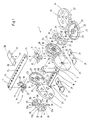
- a chain link 1 consists of two chain links 2 and 3 which are arranged at a distance from one another and parallel to one another and which are connected to one another by cross members 4 and 5.
- the cross-member 4 has a flattened cross-section over its entire length with rounded narrow sides and can be inserted into cut recesses 6 provided with undercuts in the narrow sides of the link plates 2 and 3 and connected to the link plates 2, 3 in a positive and non-positive manner by rotating them about their longitudinal axis.
- the crossmember 5 also has a flattened cross section along its entire length with rounded narrow sides and can be inserted in swivel joints 7 arranged pivotably on the narrow sides of the link plates 2 and 3.
- the swivel joints 7 consist of a pin 8 arranged in one of the link plates 2, 3 and a holder 9 which is pivotably mounted thereon and has a substantially U-shaped recess 10.
- a pin 11 is arranged in this recess 10, in which the crossmember 5 is non-positively and positively connected to the holder 9 by rotation about its longitudinal axis.
- the holder 9 also has on its underside a spring clip 12 with which the holder 9 is inserted onto the pin 8 extending in a recess 13 and in the longitudinal direction of the link plate 2, 3.
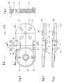
- the crossbeams 4 and 5 have a flattened cross-section with rounded narrow sides over their entire length.
- a groove 14 extending in the longitudinal direction of the crossmember 4, 5 is arranged in one side of the crossmembers 4 and 5.
- the cross members 4 and 5 have a multiplicity of bores 15.
- the pins 11 engage in the two outer bores 15 of the cross member 5 when the cross member 5 is screwed into the holder 9, so that the cross member 5 is held immovably transversely to the longitudinal direction of the chain link 1.
- the cross members 4 and 5 can optionally be attached to the link plates 2, 3 in such a way that the grooves 14 are arranged inwards or outwards.
- a separating web 16 is arranged, which is provided at the upper and lower ends with U-shaped holders 17, in which pins 18 are fastened for engagement in the bores 15 of the crossbeams 4, 5.
- the length of the pins 18 corresponds to the depth of the groove 14. In this way, the separating web 16 can be displaced in the longitudinal direction of the cross members 4, 5 when the cross members 4, 5 are fastened with inwardly directed grooves 14. If the grooves 14 of the crossbeams 4, 5 are turned outwards, the pins 18 of the separating web 16 engage in the bores 15 of the crossbeams 4, 5, so that the dividing web 16 cannot be displaced in the longitudinal direction of the crossbeams 4, 5. It is also possible to use a plurality of separating webs 16 between the cross members 4, 5 of a chain link 1.
- skids 19 are releasably attached, which slide on each other when the upper run of an energy chain is supported on the lower run.
- the length of the skids 19 is dimensioned such that the distances between the skids 19 of adjacent link plates 2, 2a are bridged.
- the skids are directly on the lower narrow side of the link plates 2, 3 and indirectly attached to the upper narrow sides of the link plates 2, 3, namely to the holder 9 of the swivel joint 7.
- Each skid 19 is plate-shaped and has on its surface facing away from the narrow sides of the link plates 2, 3 two bevels 20 arranged in the longitudinal direction. On the underside of the skids 19, four locking elements 21 are arranged, which in corresponding recesses 22 on the link plates 2, 3 and are insertable on the brackets 9.
- the mutual swivel angle of adjacent chain links is limited by stop cams 23 and 24 and a stop insert 25.
- the stop cams 24 of the link plate 2 are arranged in a recess 26 of the link plate 2 and aligned in the longitudinal direction of the link plate 2.
- the stop cams 23 at one end of the link plate 2a are arranged in corresponding recesses 26, 27 at 90 ° in comparison to the stop cams 24 at the other end of the same link plate 2a. Accordingly, the connecting line between the stop cams 23 is perpendicular to the longitudinal axis of the chain link 2a, while the other two stop cams 24 lie on the longitudinal axis of the link plate 2a.
- the link plates 2, 3 have an edge 28 encompassing the recess 26, the outer diameter of which is slightly smaller than the inner diameter of the circular recess 27 into which the edge 28 engages.
- the stop inserts 25 have a central bore 32 through which corresponding pins 33 arranged in the recesses 26, 27 engage.
- the link plates 2, 2a of adjacent chain links are connected to one another by means of connecting elements 34, the stop inserts 25 being arranged in the recess 26 or 27 of the link plates 2, 2a in such a way that the slots 29 encompass the stop cam 24, which extends in the radial direction Has recess 26 extending slot 35.
- the stop insert 25 is held non-rotatably in the link plate 2.
- the stop cams 23 are guided in the chain link 2a in the diametrically opposite recesses 30 of the stop insert 25.
- the mutual swivel angle between the chain link 1 and an adjacent chain link shown only by the chain link 2a is limited by the stop surfaces 31a and 31b. Due to the right-angled arrangement of the abutment surfaces 31a to the slots 29 and the formation of the recess 30, the adjacent chain links can only be pivoted in one direction by an angle corresponding to the angle of the recess 30 from an extended position. In order to change the pivoting direction of the chain links relative to one another, it is only necessary to insert the stop inserts 25 into the recesses 26, 27 rotated by 180 ° about one of their axes X or Y.
- the plastic stop inserts 25 have molded-in markings 36, which can be recognized through corresponding openings 37 in the link plates 2, 3, 2a.
- two pins 39 are arranged on opposite surfaces 38 of the V-shaped recesses 13.
- Brackets 40 are inserted into the V-shaped recesses 13 so as to be pivotable, the brackets 40 each having two undercut recesses 41 that fit onto the pins 39.
- the holder 40 is V-shaped on its side facing the energy guide channel, so that it completely fills the V-shaped recess 13.
- the holder 40 is U-shaped on its side facing the outside of the link plate 2, 2a, 3, so that a gap is arranged between the holder 40 and the V-shaped recess 13.
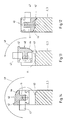
- the holder 40 has an attachment 42 which engages in a corresponding step 43 in the recess 13. This step serves as a stop surface.
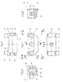
- the holder 40 is shown in detail in FIGS. 7 to 9. It can be seen that part of the underside 44 of the holder 40 facing the chain link 2, 3 is designed as a circular arc section. This circular arc section lies at the end of the holder 40 opposite the attachment 42.
- the recess 41 with an undercut 45 can be seen in FIG. 11.
- the undercuts 45 in the recesses 41 hold the bracket 40 on the pin 39, so that accidental opening of the chain link 1 is avoided.
- An easy opening of the chain link is achieved in that the holder 40 consists of a permanently elastic plastic.
- the elasticity of the holder 40 required when opening and closing the chain link 1 is improved in that slots 46 run parallel to the recesses 41. These slots 46 allow the undercut 45 to escape when the holder 40 is plugged on and when it is pulled off or off the pin 39.
- the holder 40 has an undercut U-shaped recess 10 into which the cross member 5 can be screwed.
- the pin 11 is arranged, which engages in the corresponding bore 15 in the cross member.
- extensions 47 extending in the longitudinal direction of the crossmember are arranged on both sides of the recess 10.
- FIG. 12 shows the link plate 2, 3 with the holder 40 inserted. In this position of the holder 40 shown, the shoulder 42 engages in the step 43.
- the chain link 1 is closed with the cross member 5, not shown in FIG. 13, the pivoting direction of the holder 40 is shown by an arrow 48 at an angle of 90 °.
- an arrow 49 in FIG. 14 shows the pivoting direction of the holder 40, which is now pivoted by 180 ° with respect to the position shown in FIG. 12.
Abstract
Description
Die Erfindung betrifft eine Energieführungskette zum Führen von Energieleitern, insbesondere Kabel oder Schläuche von einem festen Anschluß zu einem beweglichen Verbraucher, bestehend aus einer Vielzahl von Kettengliedern, die aus zwei im Abstand voneinander und parallel zueinander angeordneten Kettenlaschen und zwei die Kettenlaschen untereinander verbindenden Traversen bestehen, denen zumindest eine Traverse um eine Gelenkachse schwenkbeweglich an einer Kettenlasche befestigt ist.The invention relates to an energy guide chain for guiding energy conductors, in particular cables or hoses from a fixed connection to a movable consumer, consisting of a plurality of chain links which consist of two chain links arranged at a distance from one another and parallel to one another and two crossbars connecting the chain links to one another, which at least one cross member is pivotally attached to a link plate about a hinge axis.
Eine gattungsgemäße Energieführungskette ist beispielsweise aus der DE-PS 33 18 365 bekannt. Diese vorbekannte Energieführungskette besteht aus einem einteilig und formstabil ausgebildeten, U-förmigen Aufnahmeteil, dessen Schenkel Außenlaschen mit Anschlägen zur Begrenzung des gegenseitigen Schwenkwinkels bilden. Die Außenlaschen sind auf einer Seite mit einer einteilig angeformten Traverse verbunden, während eine weitere Traverse aus einem getrennten Schließbügel besteht, der die freien Enden der Außenlaschen miteinander verbindet. Dieser Schließbügel ist mit einem lösbaren Scharnier an einer Außenlasche angelenkt und an der anderen Außenlasche mit einem elastischen Haken verriegelbar. Das Scharnier besteht aus einer in die freie Kante einer Außenlasche freiliegend eingeformten Gelenkachse mit senkrecht zu den Außenlaschen abgeflachtem Kreisquerschnitt und abgerundeten Schmalseiten und aus einer in das Ende des Schließbügels eingeformten, mit Hinterschneidungen versehenen, angeschnittenen, teilkreisförmigen Ausnehmung. Diese Ausgestaltung ermöglicht, daß der Schließbügel nach dem Aufstecken auf die Gelenkachse und Verschwenken in Richtung auf die gegenüberliegende Außenlasche kraft- und formschlüssig mit der Gelenkachse verspannt ist.A generic energy chain is known for example from DE-PS 33 18 365. This known energy chain consists of a one-piece and dimensionally stable, U-shaped receiving part, the legs of which form outer plates with stops to limit the mutual pivoting angle. The outer straps are connected on one side with a cross-piece that is integrally formed, while another cross-piece consists of a separate striker that connects the free ends of the outer straps to one another. This striker is articulated with a detachable hinge on an outer plate and lockable with an elastic hook on the other outer plate. The hinge consists of an articulated axis exposed in the free edge of an outer plate with a circular cross section flattened perpendicular to the outer plates and rounded narrow sides, and of an undercut formed into the end of the striker provided, cut, part-circular recess. This configuration enables the striker to be non-positively and positively clamped to the hinge axis after it has been slipped onto the hinge axis and pivoted in the direction of the opposite outer link plate.
Diese vorbekannte Energieführungskette hat sich zur Führung von Energieleitungen bewährt. Insbesondere ist die Energieführungskette durch Verschwenken des Schließbügels leicht zu öffnen, so daß der Energieführungskanal von einer Seite gut zugänglich ist.This previously known energy chain has proven itself for the management of power lines. In particular, the energy chain can be easily opened by pivoting the striker so that the energy channel is easily accessible from one side.
Ferner ist aus der DE-PS 37 14 056 eine gattungsgemäße Energieführungskette bekannt, die aus einer Anzahl gelenkig miteinander verbindbaren Kettengliedern besteht, welche als Spritzgußteile aus elastischem Kunststoff mit jeweils zwei Seitenlaschen und zwei Querstegen ausgebildet sind. Von diesen Querstegen ist zumindest der obere Quersteg an seinen Stirnseiten mit Rastkörpern versehen, die lösbar in korrespondierenden Rastkörperaufnahmen der Seitenlaschen steckbar sind. Bei dieser vorbekannten Energieführungskette ist zumindest ein Teil eines Drehgelenks einstückig an einem Quersteg angeordnet, so daß der Innenraum der einzelnen Kettenglieder nur durch Verschwenken dieses Quersteges um den Drehpunkt zugänglich ist. Demnach ist ein Öffnen der Kettenglieder nur dann möglich, wenn ausreichende Platzverhältnisse zum Verschwenken des Quersteges gegeben sind.Furthermore, from DE-PS 37 14 056 a generic energy chain is known, which consists of a number of articulated chain links, which are designed as injection molded parts made of elastic plastic, each with two side plates and two crossbars. Of these crossbars, at least the upper crossbar is provided on its end faces with latching bodies which can be detachably inserted into corresponding latching body receptacles in the side straps. In this known energy chain, at least part of a swivel joint is arranged in one piece on a crossbar, so that the interior of the individual chain links is accessible only by pivoting this crossbar around the pivot point. Accordingly, the chain links can only be opened if there is sufficient space to pivot the crossbar.
Schließlich ist aus der DE-PS 37 09 740 eine Energieführungskette mit im Querschnitt U-förmigen Gliedern bekannt, die zwei Seitenwangen und einen diese Seitenwangen verbindenden Steg aufweisen. Ferner weist diese vorbekannte Energieführungskette einen schwenkbar an beiden Kettenlaschen angelenkten Arm auf. Dieser Arm hat an seinen beiden freien Enden paarweise nach außen gerichtete Lagerzapfen, die in als Lageraugen dienende Bohrungen eingreifen können, welche in den Kettenlaschen in Längsrichtung angeordnet sind. Der Arm hat ferner von seinen beiden Enden ausgehende Trennschlitze, durch die Schenkel gebildet werden, an deren freien Enden die Lagerzapfen angeordnet sind. Diese Trennschlitze begrenzen mittlere Teile, welche in bezug auf die Mittelachse des Armes kürzer sind als die Schenkel, so daß ein Freiraum an den Enden der mittleren Teile entsteht. Die jeweils inneren Enden der Schenkel bzw. der mittleren Teile enden, durch die Trennschlitze bedingt, auf gleicher Höhe und gehen in einen mittleren, die Gesamtbreite des Armes einnehmenden Bereich über. Um den Arm zu lösen, ist es notwendig, zuerst einen der mittleren Teile aus seiner Normallage relativ zur Mittelebene des Armes zu biegen, wonach die beiden diesen mittleren Teil flankierenden Schenkel relativ aufeinander zu bewegbar sind und aus den korrespondierenden Bohrungen herausdrückbar sind. Es ist also bei dieser vorbekannten Energieführungskette nachteilig, daß das Öffnen der einzelnen Kettenglieder sehr umständlich und nur unter Zuhilfenahme von Werkzeugen möglich ist.Finally, from DE-PS 37 09 740 an energy chain with U-shaped links in cross section is known, which have two side walls and a web connecting these side walls. Furthermore, this known energy chain has an arm pivotably articulated on both link plates. At its two free ends, this arm has bearing journals which point outwards in pairs and which serve as bearing eyes Can engage holes, which are arranged in the link plates in the longitudinal direction. The arm also has separating slots extending from its two ends, through which legs are formed, at the free ends of which the bearing pins are arranged. These separating slots delimit middle parts, which are shorter than the legs with respect to the central axis of the arm, so that a free space is created at the ends of the middle parts. The respective inner ends of the legs or of the middle parts, due to the separating slots, end at the same height and merge into a central area that takes up the entire width of the arm. In order to release the arm, it is necessary to first bend one of the middle parts out of its normal position relative to the middle plane of the arm, after which the two legs flanking this middle part can be moved relative to one another and can be pressed out of the corresponding bores. It is disadvantageous with this known energy chain that the opening of the individual chain links is very cumbersome and only possible with the help of tools.
Ausgehend von diesem vorbekannten Stand der Technik liegt der Erfindung die Aufgabe zugrunde, eine gattungsgemäße Energieführungskette zu schaffen, die zumindest an ihrer Oberseite beidseitig, d.h. an beiden Kettenlaschen zu öffnen ist und einen ungehinderten Zugang zum Energieführungskanal zuläßt, ohne daß die Halterungen von den Kettenlaschen demontiert werden müssen.Based on this known prior art, the invention has for its object to provide a generic energy chain that can be opened at least on both sides, ie on both link plates and allows unhindered access to the energy supply channel, without having to remove the brackets from the link plates Need to become.
Die erfindungsgemäße Lösung dieser Aufgabe sieht vor, daß an beiden Kettenlaschen angeordnete Drehgelenke aus einem in Längsrichtung der Kettenlaschen angeordneten und die Gelenkachse bildenden Zapfen und aus einer lösbar auf den Zapfen ausgesteckten Halterung bestehen, daß die Halterung eine mit Hinterschneidungen versehene U-förmige Ausnehmung haben und daß die Traverse an beiden Halterungen befestigt ist, wobei die Traverse in beide Halterungen eindrehbar ist.The solution to this problem according to the invention provides that swivel joints arranged on both link plates consist of a pin arranged in the longitudinal direction of the link plates and forming the hinge axis and of a holder which is detachably inserted on the pin, that the holder have an undercut U-shaped recess and that the Traverse is attached to both brackets, the crossbar can be screwed into both brackets.
Die Kettenglieder einer nach dieser technischen Lehre ausgebildeten Energieführungskette haben den Vorteil, daß sie in einfacher Weise durch Lösen einer die Traverse haltenden Halterung von dem die Gelenkachse bildenden Zapfen und gemeinsames Verschwenken der Traverse mit der Halterung um den Zapfen der zweiten Kettenlasche geöffnet werden können. Eine derartige Öffnungsweise ist dann geboten, wenn ausreichende Raumverhältnisse vorliegen, die ein Verschwenken der Traverse um den in der Kettenlasche angeordneten Zapfen erlauben. Die Kettenglieder einer Energieführungskette werden zur Wartung, zur Ergänzung oder zur Entnahme von Energieleitern geöffnet. Hierzu stellt die erfindungsgemäß ausgebildete Energieführungskette zwei Möglichkeiten zur Verfügung. Zum einen kann die Energieführungskette in der zuvor beschriebenen Art und Weise durch verschwenken der Traverse geöffnet werden. Zum anderen ist es jedoch auch möglich, die Energieführungskette dadurch zu öffnen, daß die Traverse aus den Halterungen herausgedreht wird, ohne daß die Halterungen von den die Gelenkachse bildenden Zapfen gelöst werden müssen. Diese zweite Art der Öffnung der Energieführungskette ist auch bei beschränkten Raumverhältnissen möglich, die ein Verschwenken der Traverse um die Gelenkachse nicht zulassen. Ferner ist es auf diese Art ohne Probleme möglich, die Traversen der erfindungsgemäßen Energieführungskette auszutauschen, ohne daß auch die als Teil der Drehgelenke ausgebildeten Halterungen ausgetauscht werden müssen. Hieraus folgt insbesondere der Vorteil, daß der Austausch der Traversen für den Anwender der erfindungsgemäßen Energieführungskette mit geringen Kosten verbunden ist. Schließlich wird durch die erfindungsgemäße Ausbildung der Energieführungskette der Vorteil erzielt, daß die Energieführungskette in Form eines Baukastensystems mit verschiedenen Traversen angeboten werden kann. Ein nachträgliches Umrüsten der Energieführungskette mit unterschiedlichen Traversen ist ohne Austausch bzw. Veränderungen der kostenintensiv herzustellenden Drehgelenke, welche aus in den Kettenlaschen integrierten Zapfen und aus auf diese Zapfen aufgesteckten Halterungen bestehen, möglich.The chain links of an energy guiding chain designed according to this technical teaching have the advantage that they can be opened in a simple manner by loosening a holder holding the crossbar from the pin forming the hinge axis and pivoting the crossbar together with the holder around the pin of the second link plate. This type of opening is required if there is sufficient space available to allow the crossbeam to pivot about the pin arranged in the link plate. The chain links of an energy chain are opened for maintenance, to supplement or to remove energy conductors. The energy supply chain designed according to the invention provides two options for this. On the one hand, the energy supply chain can be opened in the manner described above by pivoting the crossbar. On the other hand, however, it is also possible to open the energy chain by unscrewing the cross member from the brackets without having to loosen the brackets from the pins that form the hinge axis. This second type of opening of the energy supply chain is also possible with limited space, which does not allow the crossbeam to pivot about the joint axis. Furthermore, it is possible in this way without problems to replace the crossbeams of the energy chain according to the invention, without the brackets formed as part of the swivel joints also having to be replaced. This results in particular in the advantage that the exchange of the trusses is associated with low costs for the user of the energy chain according to the invention. Finally, the design of the energy supply chain according to the invention has the advantage that the energy supply chain can be offered in the form of a modular system with different traverses. A Subsequent retrofitting of the energy chain with different traverses is possible without replacing or changing the costly to produce swivel joints, which consist of pins integrated in the link plates and brackets attached to these pins.
Bei einer vorteilhaften Ausgestaltung der erfindungsgemäßen Energieführungskette sind die Zapfen in V-förmigen Ausnehmungen der Kettenlaschen angeordnet, so daß die Kettenlaschen durch die Integration der Zapfen keine über die Außenkontur der Energieführungskette hervorstehenden Teile aufweisen. Die Halterungen sind V-förmig ausgebildet und haben an ihrer Unterseite eine Federklammer, mit der sie auf die Zapfen aufsteckbar sind. Diese Ausgestaltung hat den Vorteil, daß die Halterungen die V-förmigen Ausnehmungen der Kettenlaschen vollständig ausfüllen, so daß keine Verschmutzung in den geschlossenen Energieführungskanal eintreten können. Insbesondere wird der Eintritt von Metallspänen oder dgl. verhindert. Ferner ist es bei dieser erfindungsgemäßen Weiterbildung vorteilhaft, daß die Halterungen in einfacher Weise mittels der Federklammern auf die Zapfen gesteckt oder von diesen abgezogen werden können. Hierdurch wird eine sehr einfache Handhabung erzielt, die auch ein vollständiges Entfernen der Halterungen mit den daran befestigten Traversen ermöglicht. Die Halterungen und die Federklammern sind vorzugsweise aus einem Kunststoff gefertigt, der eine ausreichende Elastizität aufweist, so daß die Federklammern auch nach mehrmaligem Öffnen der Energieführungskette noch ausreichend fest auf die Zapfen aufsteckbar sind und ein ungewolltes Öffnen der einzelnen Kettenglieder verhindert.In an advantageous embodiment of the energy chain according to the invention, the pins are arranged in V-shaped recesses in the link plates, so that the link plates have no parts projecting beyond the outer contour of the energy guide chain due to the integration of the pins. The brackets are V-shaped and have a spring clip on the underside with which they can be attached to the pin. This configuration has the advantage that the brackets completely fill the V-shaped recesses in the link plates, so that no contamination can enter the closed energy supply duct. In particular, the entry of metal chips or the like is prevented. Furthermore, it is advantageous in this further development according to the invention that the holders can be simply plugged onto or removed from the pins by means of the spring clips. In this way, very simple handling is achieved, which also enables the holders with the cross members attached to them to be removed completely. The brackets and the spring clips are preferably made of a plastic that has sufficient elasticity so that the spring clips can still be firmly attached to the pins even after the energy chain has been opened several times and prevents the individual chain links from opening unintentionally.
Die Halterungen sind um einen Winkel von mehr als 90° um die Zapfen zur Außenseite der Kettenlaschen schwenkbar. Durch diese Ausgestaltung ist die Traverse so weit schwenkbar, daß der Energieführungskanal weit geöffnet werden kann.The brackets can be pivoted through an angle of more than 90 ° around the pins to the outside of the link plates. With this configuration, the traverse can be pivoted so far that the energy supply channel can be opened wide.
Bei einer zweiten Ausführungsform sind an gegenüberliegenden Flächen von Ausnehmungen der Kettenlaschen zwei Zapfen angeordnet, wobei die Halterungen zwei auf die Zapfen passende, hinterschnittene Ausnehmungen aufweisen. Diese Ausgestaltung ermöglicht die Verwendung verschiedener Halterungen, die je nach Anwendungsfall V-förmig oder U-förmig ausgebildet sind. Ein weiterer Vorteil dieser Ausgestaltung ist, daß der Schwenkbereich jeder Halterung um die zwei Zapfen groß ist. Schließlich ist diese Ausführungsform auch bei kleineren Energieführungsketten verwendbar.In a second embodiment, two pins are arranged on opposite surfaces of recesses in the link plates, the holders having two undercut recesses that fit onto the pins. This configuration enables the use of different brackets which are V-shaped or U-shaped depending on the application. Another advantage of this embodiment is that the pivoting range of each bracket around the two pins is large. Finally, this embodiment can also be used with smaller energy chains.
Zur Erleichterung des Zusammenbaus der Energieführungskette ist vorgesehen, daß die Halterungen einen Ansatz haben, der in eine korrespondierende Stufe in der Ausnehmung der Kettenlasche eingreift. Beim Zusammenbau wird die Halterung in die Ausnehmung eingesetzt und derart verschwenkt, daß der Ansatz in die korrespondierende Stufe der Ausnehmung in der Kettenlasche eingreift. In dieser Stellung kann dann die Traverse an den sich gegenüberliegenden Halterungen befestigt werden.To facilitate the assembly of the energy chain, it is provided that the brackets have an approach which engages in a corresponding step in the recess of the link plate. When assembling the holder is inserted into the recess and pivoted such that the approach engages in the corresponding step of the recess in the link plate. In this position, the traverse can then be attached to the opposite brackets.
Eine leichte und reibungsfreie Verschwenkbarkeit der Halterungen wird dadurch erzielt, daß die der Kettenlasche zugewandten Unterseiten der Halterungen als Kreisbogenabschnitt ausgebildet sind.An easy and frictionless pivoting of the brackets is achieved in that the undersides of the brackets facing the chain link are designed as a circular arc section.
Die Halterungen einer weiteren Ausführungsform sind um einen Winkel zwischen 90° und 240°, vorzugsweise 180° um den Zapfen schwenkbar.The brackets of a further embodiment can be pivoted about an angle between 90 ° and 240 °, preferably 180 °, about the pin.
Weitere Einzelheiten und Vorteile ergeben sich aus der nachfolgenden Beschreibung der Zeichnung, in denen zwei Ausführungsbeispiele der Erfindung dargestellt sind. In den Zeichnungen zeigt:
- Fig. 1
- eine Energieführungskette mit einer ersten Ausführungsform des Drehgelenkes in einem perspektivischen Sprengbild;
- Fig. 2
- eine Energieführungskette mit einer zweiten Ausführungsform des Drehgelenkes in einem perspektivischen Sprengbild;
- Fig. 3
- eine Kettenlasche mit dem Drehgelenk gemäß Fig. 2 in einer Ansicht;
- Fig. 4
- die Kettenlasche gemäß Fig. 3 in einer entlang der Linie IV-IV geschnittenen Seitenansicht;
- Fig. 5
- die Kettenlasche gemäß den
Figuren 3 und 4 in einer Draufsicht entlang der Linie V-V; - Fig. 6
- die Kettenlasche gemäß den
Figuren 3 bis 5 in einer Draufsicht entlang der Linie VI-VI; - Fig. 7
- eine Halterung in Ansicht;
- Fig. 8
- die Halterung gemäß Fig. 7 in einer Draufsicht entlang der Linie VIII-VIII;
- Fig. 9
- die Halterung
gemäß den Figuren 7 und 8 in einer Draufsicht entlang der Linie IX-IX; - Fig. 10
- die Halterung
gemäß den Figuren 7bis 9 in einer geschnittenen Seitenansicht entlang der Linie X-X; - Fig. 11
- die Halterung
gemäß den Figuren 7bis 10 in einer Seitenansicht entlang der Linie XI-XI; - Fig. 12
- eine Kettenlasche mit der Halterung gemäß
den Figuren 7bis 11 in einer geschnittenen Seitenansicht; - Fig. 13
- die Kettenlasche gemäß Fig. 12 mit der um 90° verschwenkten Halterung und
- Fig. 14
- die Kettenlasche gemäß Fig. 12 mit der um 180° verschwenkten Halterung.
- Fig. 1
- an energy chain with a first embodiment of the swivel in a perspective exploded view;
- Fig. 2
- an energy chain with a second embodiment of the swivel in a perspective exploded view;
- Fig. 3
- a chain link with the swivel joint according to Figure 2 in a view.
- Fig. 4
- 3 in a side view cut along the line IV-IV;
- Fig. 5
- the chain link according to Figures 3 and 4 in a plan view along the line VV;
- Fig. 6
- the chain link according to Figures 3 to 5 in a plan view along the line VI-VI;
- Fig. 7
- a bracket in view;
- Fig. 8
- 7 in a plan view along the line VIII-VIII;
- Fig. 9
- the holder according to Figures 7 and 8 in a plan view along the line IX-IX;
- Fig. 10
- the holder according to Figures 7 to 9 in a sectional side view along the line XX;
- Fig. 11
- the holder according to Figures 7 to 10 in a side view along the line XI-XI;
- Fig. 12
- a chain link with the bracket according to Figures 7 to 11 in a sectional side view;
- Fig. 13
- 12 with the bracket pivoted by 90 ° and
- Fig. 14
- 12 with the bracket pivoted through 180 °.
Ein Kettenglied 1 besteht aus zwei im Abstand voneinander und parallel zueinander angeordneten Kettenlaschen 2 und 3, die mit Traversen 4 und 5 untereinander verbunden sind. Die Traverse 4 hat auf ihrer Gesamtlänge einen abgeflachten Querschnitt mit abgerundeten Schmalseiten und kann in mit Hinterschneidungen versehene angeschnittene Ausnehmungen 6 in den Schmalseiten der Kettenlaschen 2 und 3 eingelegt und durch Verdrehen um ihre Längsachse kraft- und formschlüssig mit den Kettenlaschen 2, 3 verbunden werden. Die Traverse 5 hat ebenfalls auf ihrer gesamten Länge einen abgeflachten Querschnitt mit abgerundeten Schmalseiten und kann in schwenkbar an den Schmalseiten der Kettenlaschen 2 und 3 angeordneten Drehgelenken 7 eingelegt werden.A chain link 1 consists of two
Die Drehgelenke 7 bestehen aus einem, in einer der Kettenlaschen 2, 3 angeordnetem Zapfen 8 und einer darauf schwenkbar aufgesteckten Halterung 9, welche eine im wesentlichen U-förmige Ausnehmung 10 hat. In dieser Ausnehmung 10, in der die Traverse 5 durch Verdrehen um ihre Längsachse kraft- und formschlüssig mit der Halterung 9 verbunden wird, ist ein Stift 11 angeordnet. Die Halterung 9 hat ferner an ihrer Unterseite eine Federklammer 12, mit der die Halterung 9 auf den in einer Ausnehmung 13 und in Längsrichtung der Kettenlasche 2, 3 verlaufenden Zapfen 8 gesteckt ist.The swivel joints 7 consist of a pin 8 arranged in one of the
Die Traversen 4 und 5 haben auf ihrer gesamten Länge einen abgeflachten Querschnitt mit abgerundeten Schmalseiten. In jeweils einer Seite der Traversen 4 und 5 ist eine in Längsrichtung der Traverse 4, 5 verlaufende Nut 14 angeordnet. Ferner weisen die Traversen 4 und 5 eine Vielzahl von Bohrungen 15 auf. In die beiden äußeren Bohrungen 15 der Traverse 5 greifen bei in die Halterung 9 eingedrehter Traverse 5 die Stifte 11 ein, so daß die Traverse 5 quer zur Längsrichtung des Kettengliedes 1 unverschiebbar gehalten ist. Die Traversen 4 und 5 können wahlweise derart an den Kettenlaschen 2, 3 befestigt werden, daß die Nuten 14 nach innen oder nach außen gerichtet angeordnet sind.The
Zwischen den Traversen 4, 5 ist ein Trennsteg 16 angeordnet, der am oberen und unteren Ende mit U-förmigen Halterungen 17 versehen ist, in welchen Stifte 18 für den Eingriff in die Bohrungen 15 der Traversen 4, 5 befestigt sind. Die Länge der Stifte 18 entspricht der Tiefe der Nut 14. Auf diese Weise ist der Trennsteg 16 in Längsrichtung der Traversen 4, 5 verschiebbar, wenn die Traversen 4, 5 mit nach innen gerichteten Nuten 14 befestigt sind. Sind die Nuten 14 der Traversen 4, 5 nach außen gedreht, greifen die Stifte 18 des Trennstegs 16 in die Bohrungen 15 der Traversen 4, 5, so daß der Trennsteg 16 nicht in Längsrichtung der Traversen 4, 5 verschiebbar ist. Es ist auch möglich, mehrere Trennstege 16 zwischen den Traversen 4, 5 eines Kettengliedes 1 einzusetzen.Between the
An den oberen und unteren Schmalseiten der Kettenlaschen 2, 3 sind Gleitkufen 19 lösbar befestigt, die aufeinander gleiten, wenn das obere Trum einer Energieführungskette sich auf dem unteren Trum abstützt. Dabei ist die Länge der Gleitkufen 19 so bemessen, daß die Abstände zwischen den Gleitkufen 19 benachbarter Kettenlaschen 2, 2a überbrückt werden. Die Gleitkufen sind an der unteren Schmalseite der Kettenlaschen 2, 3 unmittelbar und an den oberen Schmalseiten der Kettenlaschen 2, 3 mittelbar befestigt, nämlich an der Halterung 9 des Drehgelenks 7.On the upper and lower narrow sides of the
Jede Gleitkufe 19 ist plattenförmig ausgebildet und hat an ihrer den Schmalseiten der Kettenlaschen 2, 3 abgewandten Oberfläche zwei in Längsrichtung angeordnete Abschrägungen 20. An der Unterseite der Gleitkufen 19 sind vier Rastelemente 21 angeordnet, die in entsprechende Ausnehmungen 22 an den Kettenlaschen 2, 3 bzw. an den Halterungen 9 einschiebbar sind.Each skid 19 is plate-shaped and has on its surface facing away from the narrow sides of the
Der gegenseitige Schwenkwinkel benachbarter Kettenglieder wird durch Anschlagnocken 23 und 24 und einen Anschlageinsatz 25 begrenzt. Die Anschlagnocken 24 der Kettenlasche 2 sind in einer Ausnehmung 26 der Kettenlasche 2 angeordnet und in Längsrichtung der Kettenlasche 2 ausgerichtet. Die Anschlagnocken 23 an einem Ende der Kettenlasche 2a sind im Vergleich zu den Anschlagnocken 24 am anderen Ende der gleichen Kettenlasche 2a um 90° versetzt in entsprechenden Ausnehmungen 26, 27 angeordnet. Demzufolge steht die Verbindungslinie zwischen den Anschlagnocken 23 rechtwinklig zu der Längsachse des Kettengliedes 2a, während die beiden anderen Anschlagnocken 24 auf der Längsachse der Kettenlasche 2a liegen. Die Kettenlaschen 2, 3 haben einen die Ausnehmung 26 umgreifenden Rand 28, dessen Außendurchmesser geringfügig kleiner als der Innendurchmesser der kreisförmigen Ausnehmung 27 ist, in welche der Rand 28 eingreift.The mutual swivel angle of adjacent chain links is limited by
Der zwischen den benachbarten Kettenlaschen 2 und 2a in die Ausnehmungen 26, 27 eingesetzte Anschlageinsatz 25 ist im wesentlichen zylindrisch ausgebildet. Der Anschlageinsatz 25 hat zwei diametral gegenüberliegende Schlitze 29 und zwei Ausnehmungen 30. Die Schlitze 29 haben eine den Anschlagnocken 23 bzw. 24 entsprechende Breite, wogegen sich die Ausnehmungen 30 über einen den Schwenkwinkel benachbarter Kettenglieder bestimmenden Kreisbogenabschnitt erstrecken. Die Ausnehmungen 30 haben jeweils eine Anschlagfläche 31a und eine Anschlagfläche 31b, wobei auch die Anschlagflächen 31a und 31b jeweils diametral gegenüberliegend an dem Anschlageinsatz 25 angeordnet sind. In dem dargestellten Ausführungsbeispiel sind die Anschlagflächen 31a um 90° im mathematisch positiven Drehsinn versetzt zu den Schlitzen 29 angeordnet. Der Winkel zwischen den Anschlagflächen 31a und 31b beträgt in dem dargestellten Ausführungsbeispiel ungefähr 60°.The
Die Anschlageinsätze 25 haben eine zentrale Bohrung 32 durch die entsprechende, in den Ausnehmungen 26, 27 angeordnete Zapfen 33 greifen. Die Kettenlaschen 2, 2a benachbarter Kettenglieder werden mittels Verbindungselementen 34 miteinander verbunden, wobei die Anschlageinsätze 25 derart in der Ausnehmung 26 bzw. 27 der Kettenlaschen 2, 2a angeordnet sind, daß die Schlitze 29, den Anschlagnocken 24 umgreifen, der einen in radialer Richtung der Ausnehmung 26 verlaufenden Schlitz 35 aufweist. Hierdurch ist der Anschlageinsatz 25 unverdrehbar in der Kettenlasche 2 gehalten. Bei dieser Anordnung sind die Anschlagnocken 23 in der Kettenlasche 2a in den diametral gegenüberliegenden Ausnehmungen 30 des Anschlageinsatzes 25 geführt. Durch die Anschlagflächen 31a und 31b wird der gegenseitige Schwenkwinkel zwischen dem Kettenglied 1 und einem nur durch die Kettenlasche 2a dargestellten benachbarten Kettenglied begrenzt. Durch die rechtwinklige Anordnung der Anschlagflächen 31a zu den Schlitzen 29 und der Ausbildung der Ausnehmung 30 können die benachbarten Kettenglieder aus einer gestreckten Lage nur in eine Richtung um einen dem Winkel der Ausnehmung 30 entsprechenden Winkel verschwenkt werden. Um die Verschwenkrichtung der Kettenglieder zueinander zu verändern, ist es lediglich notwendig, die Anschlageinsätze 25 um 180° um eine ihrer Achsen X oder Y verdreht in die Ausnehmungen 26, 27 einzulegen.The stop inserts 25 have a
Zur Anzeige der Schwenkrichtung und des Schwenkwinkels haben die aus Kunststoff bestehenden Anschlageinsätze 25 eingeformte Kennzeichnungen 36, welche durch entsprechende Öffnungen 37 in den Kettenlaschen 2, 3, 2a erkennbar sind.To indicate the swivel direction and the swivel angle, the plastic stop inserts 25 have molded-in
Bei dem in der Fig. 2 dargestellten Ausführungsbeispiel eines Kettengliedes 1 sind an gegenüberliegenden Flächen 38 der V-förmigen Ausnehmungen 13 zwei Zapfen 39 angeordnet. In die V-förmigen Ausnehmungen 13 sind Halterungen 40 schwenkbeweglich eingesetzt, wobei die Halterungen 40 jeweils zwei auf die Zapfen 39 passende, hinterschnittene Ausnehmungen 41 aufweisen.In the embodiment of a chain link 1 shown in FIG. 2, two
Die Halterung 40 ist an ihrer dem Energieführungskanal zugewandten Seite V-förmig ausgebildet, so daß sie die V-förmige Ausnehmung 13 vollständig ausfüllt. Die Halterung 40 ist an ihrer dem Äußeren der Kettenlasche 2, 2a, 3 zugewandten Seite U-förmig ausgebildet, so daß zwischen der Halterung 40 und der V-förmigen Ausnehmung 13 ein Spalt angeordnet ist. Wie insbesondere aus den Figuren 3 bis 5 zu erkennen ist, hat die Halterung 40 einen Ansatz 42, der in eine korrespondierende Stufe 43 in der Ausnehmung 13 eingreift. Diese Stufe dient als Anschlagfläche. Beim Zusammenbau der Kettenglieder wird die Halterung 40 derart eingesetzt, daß der Ansatz 42 in der Stufe 43 anliegt, so daß die Halterung 40 eine definierte Position zum Einsatz der Traverse 5 einnimmt.The
In den Figuren 7 bis 9 ist die Halterung 40 detailliert dargestellt. Es ist zu erkennen, daß ein Teil der der Kettenlasche 2, 3 zugewandten Unterseite 44 der Halterung 40 als Kreisbogenabschnitt ausgebildet ist. Dieser Kreisbogenabschnitt liegt an dem dem Ansatz 42 gegenüberliegenden Ende der Halterung 40. In der Fig. 11 ist die Ausnehmung 41 mit einer Hinterschneidung 45 erkennbar. Die Hinterschneidungen 45 in den Ausnehmungen 41 halten die Halterung 40 auf den Zapfen 39, so daß ein unbeabsichtigtes Öffnen des Kettengliedes 1 vermieden wird. Ein leichtes Öffnen des Kettengliedes wird dadurch erzielt, daß die Halterung 40 aus einem dauerelastischen Kunststoff besteht. Die beim Öffnen und Schließen des Kettengliedes 1 erforderliche Elastizität der Halterung 40 wird dadurch verbessert, daß parallel zu den Ausnehmungen 41 Schlitze 46 verlaufen. Diese Schlitze 46 ermöglichen ein Ausweichen der Hinterschneidung 45 beim Aufstecken und beim Abziehen der Halterung 40 auf bzw. von den Zapfen 39.The
Wie insbesondere aus der Fig. 7 zu erkennen ist, hat die Halterung 40 eine mit Hinterschneidungen versehene U-förmige Ausnehmung 10 in die die Traverse 5 eindrehbar ist. In diese Ausnehmung 10 ist der Stift 11 angeordnet, welcher in die korrespondierende Bohrung 15 in der Traverse greift. Zur Führung der Traverse 5 sind an beiden Seiten der Ausnehmung 10 sich in Längsrichtung der Traverse erstreckende Ansätze 47 angeordnet.As can be seen in particular from FIG. 7, the
In der Fig. 12 ist die Kettenlasche 2, 3 mit der eingesetzten Halterung 40 dargestellt. In dieser dargestellten Stellung der Halterung 40 greift der Ansatz 42 in die Stufe 43. Das Kettenglied 1 ist mit der in der Fig. 12 nicht dargestellten Traverse 5 verschlossen. In der Fig. 13 ist mit einem Pfeil 48 die Schwenkrichtung der Halterung 40 um einen Winkel von 90° dargestellt. Schließlich zeigt in der Fig. 14 ein Pfeil 49 die Schwenkrichtung der nunmehr um 180° gegenüber der in Fig. 12 dargestellten Stellung verschwenkten Halterung 40.
Claims (10)
- A power guide chain for guiding power conductors, particularly cables or pipes, from a fixed terminal to a movable consumer, comprising a plurality of chain links (1) which comprise two link plates (2, 3) arranged parallel to and spaced from each other and two cross-pieces (4, 5) which join together the link plates, of which cross-pieces at least one (5) is fixed to a link plate (2, 3) for pivotal movement about a pivot axis,
characterised in that
hinges (7) arranged on both link plates (2, 3) comprise a pin (8) arranged in the longitudinal direction of the link plates (2, 3) and forming the pivot axis, and a mounting means (9) which is detachably attached to the pin (8),
the mounting means (9) have a U-shaped recess (10) provided with undercut portions and
the cross-piece (5) is fixed to both mounting means (9), wherein the cross-piece (5) is able to be twisted into both mounting means (9). - A power guide chain according to Claim 1, characterised in that the pins (8) are arranged in V-shaped recesses (13) in the chain links.
- A power guide chain according to Claim 1, characterised in that the mounting means (9) are V-shaped and have a spring clip (12) on their underside, by means of which they are able to be attached to the pins (8).
- A power guide chain according to Claim 1, characterised in that the mounting means (9) are pivotable through an angle greater than 90° about the pins (8) towards the outside of the link plates (2, 3).
- A power guide chain according to Claim 1, characterised in that two pins (39) are arranged on the oppositely disposed faces (38) of V-shaped recesses (13) of the link plates (2, 3) and that the mounting means (40) have undercut recesses (41) which fit the pins (39).
- A power guide chain according to Claim 5, characterised in that the mounting means (40) are U-shaped.
- A power guide chain according to Claim 6, characterised in that the mounting means (40) have a projection (42) which engages into a corresponding step (43) in the recess (13).
- A power guide chain according to Claim 5, characterised in that the undersides (44) of the mounting means (40), facing the link plate (2, 3), are designed with an arcuate section.
- A power guide chain according to Claim 1, characterised in that a pin (11) is arranged in the recesses (10), the pin engaging into a corresponding bore (15) in the cross-piece (5).
- A power guide chain according to Claim 5, characterised in that the mounting means (40) are pivotable through an angle of between 90° and 240°, preferably 180°, about the pins (8).
Applications Claiming Priority (2)
| Application Number | Priority Date | Filing Date | Title |
|---|---|---|---|
| DE4105653A DE4105653A1 (en) | 1991-02-22 | 1991-02-22 | POWER SUPPLY CHAIN |
| DE4105653 | 1991-02-22 |
Publications (2)
| Publication Number | Publication Date |
|---|---|
| EP0499809A1 EP0499809A1 (en) | 1992-08-26 |
| EP0499809B1 true EP0499809B1 (en) | 1994-12-07 |
Family
ID=6425707
Family Applications (1)
| Application Number | Title | Priority Date | Filing Date |
|---|---|---|---|
| EP92100962A Expired - Lifetime EP0499809B1 (en) | 1991-02-22 | 1992-01-22 | Supporting chain for energy carriers |
Country Status (7)
| Country | Link |
|---|---|
| US (1) | US5157913A (en) |
| EP (1) | EP0499809B1 (en) |
| JP (1) | JP3010539B2 (en) |
| KR (1) | KR950007522B1 (en) |
| AT (1) | ATE115246T1 (en) |
| DE (2) | DE4105653A1 (en) |
| ES (1) | ES2066496T3 (en) |
Cited By (1)
| Publication number | Priority date | Publication date | Assignee | Title |
|---|---|---|---|---|
| DE19820651B4 (en) * | 1998-05-08 | 2007-04-12 | Kabelschlepp Gmbh | Cable guide assembly with a zugentlastenden attachment of at least one guided in the wiring guide line |
Families Citing this family (25)
| Publication number | Priority date | Publication date | Assignee | Title |
|---|---|---|---|---|
| US5240209A (en) * | 1992-11-17 | 1993-08-31 | Telect, Inc. | Telecommunication multiple cable carrier |
| DE4313075C2 (en) * | 1993-04-21 | 1996-07-25 | Igus Gmbh | Energy chain |
| DE4413303C1 (en) * | 1994-04-18 | 1995-05-24 | Kabelschlepp Gmbh | Traverse for energy supply chain |
| DE19523105A1 (en) * | 1995-06-26 | 1997-01-02 | Murrplastik Gmbh | Locking bracket for chain links in an energy chain |
| DE19645403A1 (en) * | 1996-11-04 | 1998-05-07 | Kabelschlepp Gmbh | Chain link and energy chain with lockable crossbar |
| DE29619833U1 (en) * | 1996-11-14 | 1998-03-19 | Kabelschlepp Gmbh | Fastening arrangement with a chain link and a fastening unit for lines |
| DE19648967A1 (en) * | 1996-11-26 | 1998-06-04 | Kabelschlepp Gmbh | Kit for a chain link that can be adapted to several applications |
| DE19701706C1 (en) * | 1997-01-21 | 1998-09-03 | Igus Gmbh | Energy supply chain |
| DE19839575A1 (en) * | 1998-08-31 | 2000-03-09 | Kabelschlepp Gmbh | Energy guiding chain for guiding cables with spatially movable chain links |
| DE19957021A1 (en) * | 1999-11-26 | 2001-05-31 | Kabelschlepp Gmbh | Energy supply unit has chain links linked together, pivoting towards central axis, bearer arrangements on at least some links, linkage axes of adjacent links mutually offset by 90 degrees |
| US6848369B1 (en) | 2000-05-02 | 2005-02-01 | Haworth, Inc. | Workstation and power and telecommunication arrangement therefor |
| US6448498B1 (en) | 2000-05-02 | 2002-09-10 | Haworth, Inc. | Flexible raceway arrangement for cabling |
| DE10339168A1 (en) | 2003-08-21 | 2005-04-28 | Kabelschlepp Gmbh | Chain link for an energy chain and energy chain |
| DE10346653A1 (en) | 2003-10-08 | 2005-06-09 | Kabelschlepp Gmbh | Chain link, chain link and energy guiding chain, as well as intermediate piece for an energy guiding chain, with torsion-coupled locking means for connecting crosspiece and link plate |
| DE102004022512A1 (en) * | 2004-05-05 | 2005-12-01 | Kabelschlepp Gmbh | Chain link for an energy supply chain and energy supply chain with extended usage cross-section |
| DE102005013430A1 (en) * | 2005-03-21 | 2006-09-28 | Murrplastik Systemtechnik Gmbh | Chain link for an energy chain |
| JP4137117B2 (en) * | 2005-12-27 | 2008-08-20 | 株式会社椿本チエイン | Cable protection guide device |
| FR2917912B1 (en) * | 2007-06-20 | 2010-04-16 | Cqfd Composites | CABLE ROUTING DEVICE FOR PARTICULAR PARTICIPATION IN THE ROUTING AND DISTRIBUTION OF ELECTRIC CABLES |
| US20120126067A1 (en) * | 2007-06-20 | 2012-05-24 | Frank Chauzu | Cable routing device |
| JP4751862B2 (en) * | 2007-08-08 | 2011-08-17 | 株式会社椿本チエイン | Cable protection guide device |
| DE102008046700A1 (en) * | 2008-09-10 | 2010-03-11 | Murrplastik Systemtechnik Gmbh | Chain link for an energy chain |
| JP5047197B2 (en) * | 2009-01-07 | 2012-10-10 | 株式会社椿本チエイン | Cable protection guide device |
| JP5350445B2 (en) * | 2011-08-03 | 2013-11-27 | 株式会社椿本チエイン | Cable protection guide device |
| DE102016000864A1 (en) * | 2016-01-28 | 2017-08-03 | Murrplastik Systemtechnik Gmbh | Power supply chain |
| DE202019100877U1 (en) * | 2019-02-15 | 2020-03-17 | Igus Gmbh | End fastening part for an energy chain |
Family Cites Families (10)
| Publication number | Priority date | Publication date | Assignee | Title |
|---|---|---|---|---|
| DE3318365A1 (en) * | 1983-05-20 | 1984-11-22 | Kabelschlepp Gmbh, 5900 Siegen | POWER SUPPLY CHAIN |
| US4590961A (en) * | 1985-08-16 | 1986-05-27 | Cooper Industries, Inc. | Modular rolling conductor support |
| DE8528258U1 (en) * | 1985-10-04 | 1985-11-14 | Kabelschlepp Gmbh, 5900 Siegen | Energy chain |
| IT209828Z2 (en) * | 1987-01-02 | 1988-11-04 | Mauri Giovanni | CURVILINEAR DEVELOPMENT CABLE CHAIN.! |
| DE3709740A1 (en) * | 1987-03-25 | 1988-10-06 | Ernst Klein | Self-supporting power-supply chain which can be bent on one side |
| US4833876A (en) * | 1987-04-09 | 1989-05-30 | Tsubakimoto Chain Co. | Carrier for cables and the like |
| DE3714056C1 (en) * | 1987-04-28 | 1988-08-25 | Murr Plastik Gmbh | Energy management chain |
| DE8910217U1 (en) * | 1989-08-26 | 1989-10-05 | Kabelschlepp Gmbh, 5900 Siegen, De | |
| DE9102122U1 (en) * | 1991-02-22 | 1991-05-16 | Kabelschlepp Gmbh, 5900 Siegen, De | |
| DE9102121U1 (en) * | 1991-02-22 | 1991-05-16 | Kabelschlepp Gmbh, 5900 Siegen, De |
-
1991
- 1991-02-22 DE DE4105653A patent/DE4105653A1/en not_active Withdrawn
-
1992
- 1992-01-22 EP EP92100962A patent/EP0499809B1/en not_active Expired - Lifetime
- 1992-01-22 ES ES92100962T patent/ES2066496T3/en not_active Expired - Lifetime
- 1992-01-22 DE DE59200874T patent/DE59200874D1/en not_active Expired - Fee Related
- 1992-01-22 AT AT92100962T patent/ATE115246T1/en not_active IP Right Cessation
- 1992-02-21 JP JP8259892A patent/JP3010539B2/en not_active Expired - Fee Related
- 1992-02-21 US US07/839,579 patent/US5157913A/en not_active Expired - Fee Related
- 1992-02-21 KR KR1019920002643A patent/KR950007522B1/en not_active IP Right Cessation
Cited By (1)
| Publication number | Priority date | Publication date | Assignee | Title |
|---|---|---|---|---|
| DE19820651B4 (en) * | 1998-05-08 | 2007-04-12 | Kabelschlepp Gmbh | Cable guide assembly with a zugentlastenden attachment of at least one guided in the wiring guide line |
Also Published As
| Publication number | Publication date |
|---|---|
| DE59200874D1 (en) | 1995-01-19 |
| ES2066496T3 (en) | 1995-03-01 |
| KR950007522B1 (en) | 1995-07-11 |
| EP0499809A1 (en) | 1992-08-26 |
| KR920016745A (en) | 1992-09-25 |
| DE4105653A1 (en) | 1992-09-03 |
| JPH0599279A (en) | 1993-04-20 |
| JP3010539B2 (en) | 2000-02-21 |
| US5157913A (en) | 1992-10-27 |
| ATE115246T1 (en) | 1994-12-15 |
Similar Documents
| Publication | Publication Date | Title |
|---|---|---|
| EP0499809B1 (en) | Supporting chain for energy carriers | |
| EP0499791B1 (en) | Supporting chain for energy carriers | |
| EP0499784B1 (en) | Supporting chain for energy carriers | |
| EP0415050B1 (en) | Supporting chain for energy carriers | |
| EP0192853B1 (en) | Energy conveying chain | |
| EP1175571B1 (en) | Cable carrier chain | |
| EP0956465B1 (en) | Chain link with insertable separating pins | |
| EP0126862A1 (en) | Supporting chain for energy carriers | |
| DE19512088A1 (en) | Energy chain | |
| DE2624429B2 (en) | Clamping means | |
| DD256902A5 (en) | cable carrier | |
| WO2010029090A1 (en) | Chain link for an energy guiding chain | |
| WO2013124370A2 (en) | Cable guide | |
| DE3516448C1 (en) | Energy-guidance chain | |
| DE3408912C1 (en) | Energy-carrying chain | |
| EP0308958B1 (en) | Chain for energy carriers | |
| DE102005061775A1 (en) | Chain link with a locking device | |
| DE2925045C2 (en) | Chain conveyor | |
| EP1705401A2 (en) | Chain link for a supporting chain for energy carriers | |
| DE19547215A1 (en) | Shelf for links of "energy guidance chain" | |
| DE19502681A1 (en) | Strain relief and fastener | |
| DE3909797C1 (en) | Energy supply chain for receiving cables and/or lines | |
| EP0557690B1 (en) | Apparatus for attaching pivotable devices | |
| DE3814995C1 (en) | Self-supporting energy-supply chain which can bend on one side | |
| DE4102774C2 (en) | Codable electrical connector |
Legal Events
| Date | Code | Title | Description |
|---|---|---|---|
| PUAI | Public reference made under article 153(3) epc to a published international application that has entered the european phase |
Free format text: ORIGINAL CODE: 0009012 |
|
| AK | Designated contracting states |
Kind code of ref document: A1 Designated state(s): AT CH DE ES FR GB IT LI NL SE |
|
| 17P | Request for examination filed |
Effective date: 19920721 |
|
| 17Q | First examination report despatched |
Effective date: 19940222 |
|
| GRAA | (expected) grant |
Free format text: ORIGINAL CODE: 0009210 |
|
| AK | Designated contracting states |
Kind code of ref document: B1 Designated state(s): AT CH DE ES FR GB IT LI NL SE |
|
| PG25 | Lapsed in a contracting state [announced via postgrant information from national office to epo] |
Ref country code: NL Effective date: 19941207 |
|
| REF | Corresponds to: |
Ref document number: 115246 Country of ref document: AT Date of ref document: 19941215 Kind code of ref document: T |
|
| REF | Corresponds to: |
Ref document number: 59200874 Country of ref document: DE Date of ref document: 19950119 |
|
| PG25 | Lapsed in a contracting state [announced via postgrant information from national office to epo] |
Ref country code: AT Effective date: 19950122 |
|
| PG25 | Lapsed in a contracting state [announced via postgrant information from national office to epo] |
Ref country code: LI Effective date: 19950131 Ref country code: CH Effective date: 19950131 |
|
| GBT | Gb: translation of ep patent filed (gb section 77(6)(a)/1977) |
Effective date: 19950112 |
|
| ITF | It: translation for a ep patent filed |
Owner name: STUDIO JAUMANN |
|
| REG | Reference to a national code |
Ref country code: ES Ref legal event code: FG2A Ref document number: 2066496 Country of ref document: ES Kind code of ref document: T3 |
|
| PG25 | Lapsed in a contracting state [announced via postgrant information from national office to epo] |
Ref country code: SE Effective date: 19950307 |
|
| ET | Fr: translation filed | ||
| NLV1 | Nl: lapsed or annulled due to failure to fulfill the requirements of art. 29p and 29m of the patents act | ||
| REG | Reference to a national code |
Ref country code: CH Ref legal event code: PL |
|
| PLBE | No opposition filed within time limit |
Free format text: ORIGINAL CODE: 0009261 |
|
| STAA | Information on the status of an ep patent application or granted ep patent |
Free format text: STATUS: NO OPPOSITION FILED WITHIN TIME LIMIT |
|
| 26N | No opposition filed | ||
| PGFP | Annual fee paid to national office [announced via postgrant information from national office to epo] |
Ref country code: ES Payment date: 19990121 Year of fee payment: 8 |
|
| PG25 | Lapsed in a contracting state [announced via postgrant information from national office to epo] |
Ref country code: ES Free format text: LAPSE BECAUSE OF NON-PAYMENT OF DUE FEES Effective date: 20000124 |
|
| REG | Reference to a national code |
Ref country code: ES Ref legal event code: FD2A Effective date: 20010910 |
|
| REG | Reference to a national code |
Ref country code: GB Ref legal event code: IF02 |
|
| PGFP | Annual fee paid to national office [announced via postgrant information from national office to epo] |
Ref country code: GB Payment date: 20030106 Year of fee payment: 12 |
|
| PGFP | Annual fee paid to national office [announced via postgrant information from national office to epo] |
Ref country code: FR Payment date: 20030116 Year of fee payment: 12 |
|
| PGFP | Annual fee paid to national office [announced via postgrant information from national office to epo] |
Ref country code: DE Payment date: 20030205 Year of fee payment: 12 |
|
| PG25 | Lapsed in a contracting state [announced via postgrant information from national office to epo] |
Ref country code: GB Free format text: LAPSE BECAUSE OF NON-PAYMENT OF DUE FEES Effective date: 20040122 |
|
| PG25 | Lapsed in a contracting state [announced via postgrant information from national office to epo] |
Ref country code: DE Free format text: LAPSE BECAUSE OF NON-PAYMENT OF DUE FEES Effective date: 20040803 |
|
| GBPC | Gb: european patent ceased through non-payment of renewal fee |
Effective date: 20040122 |
|
| PG25 | Lapsed in a contracting state [announced via postgrant information from national office to epo] |
Ref country code: FR Free format text: LAPSE BECAUSE OF NON-PAYMENT OF DUE FEES Effective date: 20040930 |
|
| REG | Reference to a national code |
Ref country code: FR Ref legal event code: ST |
|
| PG25 | Lapsed in a contracting state [announced via postgrant information from national office to epo] |
Ref country code: IT Free format text: LAPSE BECAUSE OF NON-PAYMENT OF DUE FEES Effective date: 20050122 |