EP1611927A1 - Snowglide board - Google Patents
Snowglide board Download PDFInfo
- Publication number
- EP1611927A1 EP1611927A1 EP05013199A EP05013199A EP1611927A1 EP 1611927 A1 EP1611927 A1 EP 1611927A1 EP 05013199 A EP05013199 A EP 05013199A EP 05013199 A EP05013199 A EP 05013199A EP 1611927 A1 EP1611927 A1 EP 1611927A1
- Authority
- EP
- European Patent Office
- Prior art keywords
- binding
- connecting pieces
- board according
- snow
- sliding board
- Prior art date
- Legal status (The legal status is an assumption and is not a legal conclusion. Google has not performed a legal analysis and makes no representation as to the accuracy of the status listed.)
- Granted
Links
Images


Classifications
-
- A—HUMAN NECESSITIES
- A63—SPORTS; GAMES; AMUSEMENTS
- A63C—SKATES; SKIS; ROLLER SKATES; DESIGN OR LAYOUT OF COURTS, RINKS OR THE LIKE
- A63C5/00—Skis or snowboards
- A63C5/003—Structure, covering or decoration of the upper ski surface
-
- A—HUMAN NECESSITIES
- A63—SPORTS; GAMES; AMUSEMENTS
- A63C—SKATES; SKIS; ROLLER SKATES; DESIGN OR LAYOUT OF COURTS, RINKS OR THE LIKE
- A63C5/00—Skis or snowboards
- A63C5/12—Making thereof; Selection of particular materials
- A63C5/128—A part for the binding being integrated within the board structure, e.g. plate, rail, insert
-
- A—HUMAN NECESSITIES
- A63—SPORTS; GAMES; AMUSEMENTS
- A63C—SKATES; SKIS; ROLLER SKATES; DESIGN OR LAYOUT OF COURTS, RINKS OR THE LIKE
- A63C9/00—Ski bindings
- A63C9/003—Non-swivel sole plate fixed on the ski
Definitions
- the invention relates to a snow gliding board, in particular ski, with at least one binding which is held on a SchneegleitbrettShoberseite by undercuts on Schneegleitbrett redesign engaging behind locking portions, wherein for introducing the locking portions in the undercuts insertion openings are provided, each of which transition into an undercut and preferably to the top of the snowboard are open.
- a snow gliding board in the form of a ski in which the binding is fastened to the upper side of the ski body with a bayonet-type lock (EP 0 383 104 B1).
- this locking is realized in that in both longitudinal sides of the ski body or in the local cheeks each one is introduced on the longitudinal side groove and the ski body in the region of this groove is engaged behind the angled ends of cross-sectionally C-shaped binding plates form fit ,
- recesses are additionally provided in the side cheeks through which the grooves are open to the upper side of the ski body, so that each binding plate by placing on the ski body and by subsequent longitudinal displacement on Ski emotions bayonet lockable lockable.
- the known construction has certain disadvantages, namely, inter alia, because the binding plates carrying binding plates inevitably protrude beyond the longitudinal sides of the ski body, also by the grooves in the side cheeks results in a weakening of the ski body and finally, because of the relatively low height of the side cheeks and the material commonly used for side cheeks, the strength of the anchoring of the binding to the ski body is limited.
- the object of the invention is to show a snow sliding, which, while maintaining the basic advantages of a bayonet-type fastening of the binding or binding elements u. a. the driving characteristics of the snowboard not impairing construction allows.
- a snow sliding board, in particular ski with at least one binding, which is held on a SchneegleitbrettShoberseite by undercuts on Schneegleitbrett redesign engaging behind locking portions, wherein for introducing the locking portions in the undercuts insertion openings are provided, which each pass into an undercut and preferably are open at the top of the Schneegleitbrettes, designed so that the undercuts are formed by anchored to the GleitbrettShangeoberseite connectors.
- the ski body 2 consists, for example, of the inner core 3 with a torsion box 4 surrounding this core, from which the ski body underside 2.1 forming tread surface 5 with the lateral steel edges 6, from the upper belt 7 above the core 3 and the lower belt 8 between Torsionskasten and tread 5 , from the side walls 9 forming the longitudinal sides of the ski and from a decorative and closing film 10 forming the upper side and partly also the longitudinal sides of the ski body 2.
- the core 3, the torsion box 4 and e.g. the upper belt 7 is also shaped in such a way that the ski body 2 on the ski body upper side 2.2 forms two projections 11, each extending in the longitudinal direction of the body, parallel to one another and spaced from each other, e.g. extend over the entire or almost the entire length of the ski or over a large part of the ski length.
- inner sides 11.1 of the projections 11 are in local recesses 12, which are provided in the central region of the ski body 2 and in the binding area and open to the respective other projection and the top of the ski 1, connecting pieces 13 and 14th used, and that at each projection in a direction from the rear end 2.3 of the ski body 2 to the blade area 2.2 of this ski body out first the connector 13 and then in Ski stresseslnature and spaced therefrom the further connector 14.
- the connectors 13 and 14 are in the illustrated embodiment essentially strip-like moldings 15 and 16 made of metal or plastic.
- moldings are in each case formed with a groove 17 which is open on a connecting piece longitudinal side 13.1 or 14.1 and is closed at the two ends of the respective connecting piece 13 and 14, and in a suitable manner, for example by screwing and / or by integrally formed pins and / or by gluing or the like in the recesses 12 are fixed such that the two connecting pieces 13 are perpendicular to the longitudinal extent of the ski with the open side of their grooves 17 in pairs directly opposite, as well as the two connectors 14th
- each segmented ie with perpendicular to their longitudinal extension extending groove-like cuts 18 such that each connecting piece 13 and 14 and the corresponding molded body 15 and 16 a total of four segments 15.1 - 15.4 and 16.1 - 16.4 forms.
- These are merely connected via material sections 15.5 and 16.5, which are located at the lower body of the lower body of the lower side of the respective recess 12 when the connecting pieces are mounted.
- each shaped body 15 and 16 each have the same length. Furthermore, each shaped body is divided by the cuts 18 into four segments of equal length.
- the connecting pieces 13 are each provided with an opening 19 which extends in the illustrated embodiment over the entire length of the respective segment and from the opening edge of the groove 17 to the bottom of this groove is enough.
- About the recesses 19 are provided on the underside of a binding element, for example, on the underside of a binding plate 20 provided locking portions 21 in each case a groove 17 of the connecting piece 13 by placing from above for what the length of the locking element 21 in the longitudinal direction of the binding plate 20 and the longitudinal direction of the Skis equal to or slightly smaller than the corresponding length of the recesses 19.
- the binding plate 20 By moving the binding plate 20 in the longitudinal direction by the length of a segment 15.1 - 15.4, the binding plate 20 is then anchored with its locking elements 21 to the two connectors 13 and thus on the ski body top 2.2 , In the illustrated embodiment, the binding plate 20 has on its underside two pairs of strip-like locking elements 21.
- the distance between the locking elements 21 on each longitudinal side of the binding plate 20 from each other is then also equal to the distance of the recesses 19 on the connecting pieces 13.
- the locking portions 21 are formed by a corresponding profiling of the binding plates 20.
- the rear end of the binding plate 20 is thus at each connector 13 twice, that is anchored by double attack.
- the binding plate 20 lies with its two longitudinal edges on the upper side of the projections 11 and on the upper side of the connecting pieces 13 and 14, so that for optimal power transmission between binding and ski reaches a far outward support of the binding plate 20 on the ski body 2 is.
- the rear binding element 22 is provided adjustable in the longitudinal direction of the body of the ski, as indicated by the double arrow A.
- the connecting pieces 14 and the corresponding molded parts 16 have on their upper side at the first segment 16.1 in the axial direction "ski body end 2.3 - blade 2.4" first segment 16.1 corresponding recess 23.
- the others, respectively in the direction of the ski front or in the direction of the blade area 2.4 subsequent segments 16.2 - 16.4 do not have the recess 23.
- the front binding member 24 (binding front jaws) is adjustably fixed in the longitudinal direction of the binding plate 20 (double arrow B).
- the binding element 24 is designed on its underside corresponding to the binding plate 20, with one locking section 21 on each longitudinal side.
- the binding element 20 connected to the binding plate 20 is then inserted through the recesses 23 by placing in the groove 17 of the front connecting pieces 14 and there lockable during axial displacement of the binding plate 20. Since the connecting pieces 14 more, d. H. in the illustrated embodiment, a total of three adjoining in the longitudinal direction connector segments 16.2 - 16.4 without the recess 23, is after the locking of the binding element 24 and thus also the front end of the binding plate 20 at the connecting pieces 14 and the ski body 2, a longitudinal adjustment (double arrow B ) of the binding element 24 relative to the binding plate 20 while maintaining the lock on the ski body 2 possible.
- the formation is in this case preferably such that the insertion of the locking portions 21 on the binding plate 20 and the front binding element 22 in the associated recesses 19 and 23 is possible when the front binding element 24 in one of the two end positions of its adjustment (double arrow B ) is located relative to the binding plate 20, in the illustrated embodiment in that end position in which the binding element 22 of the base plate 20 is closest.
- this lock secured by suitable means, for example by fixing the binding plate 20 on the ski body 2 by means of a pin or the like.
Abstract
Description
Die Erfindung bezieht sich auf ein Schneegleitbrett, insbesondere Ski, mit wenigstens einer Bindung, die an einer Schneegleitbrettkörperoberseite durch Hinterschneidungen am Schneegleitbrettkörper hintergreifende Verriegelungsabschnitte gehalten ist, wobei zum Einführen der Verriegelungsabschnitte in die Hinterschneidungen Einführöffnungen vorgesehen sind, die jeweils in eine Hinterschneidung übergehen und vorzugsweise an der Oberseite des Schneegleitbrettes offen sind.The invention relates to a snow gliding board, in particular ski, with at least one binding which is held on a Schneegleitbrettkörperoberseite by undercuts on Schneegleitbrettkörper engaging behind locking portions, wherein for introducing the locking portions in the undercuts insertion openings are provided, each of which transition into an undercut and preferably to the top of the snowboard are open.
Bekannt ist ein Schneegleitbrett in Form eines Skis, bei dem die Bindung mit einer bajonettartigen Verriegelung an der Oberseite des Skikörpers befestigt ist (EP 0 383 104 B1). Im Detail ist diese Verriegelung dadurch realisiert, dass in beiden Längsseiten des Skikörpers bzw. in den dortigen Wangen jeweils eine an der Längsseite offene Nut eingebracht ist und der Skikörper im Bereich dieser Nut von den abgewinkelten Enden von im Querschnitt C-förmigen Bindungsplatten formschlüssig hintergriffen wird. Um ein Einführen der abgewinkelten Enden des jeweiligen C-Profils in die Nuten zu ermöglichen, sind in den Seitenwangen zusätzlich Ausnehmungen vorgesehen, über die die Nuten zur Skikörperoberseite hin seitlich offen sind, so dass jede Bindungsplatte durch Aufsetzen auf den Skikörper und durch anschließendes Längsverschieben am Skikörper bajonettverschlussartig verriegelbar ist.A snow gliding board in the form of a ski is known, in which the binding is fastened to the upper side of the ski body with a bayonet-type lock (EP 0 383 104 B1). In detail, this locking is realized in that in both longitudinal sides of the ski body or in the local cheeks each one is introduced on the longitudinal side groove and the ski body in the region of this groove is engaged behind the angled ends of cross-sectionally C-shaped binding plates form fit , In order to allow insertion of the angled ends of the respective C-profile in the grooves, recesses are additionally provided in the side cheeks through which the grooves are open to the upper side of the ski body, so that each binding plate by placing on the ski body and by subsequent longitudinal displacement on Skikörper bayonet lockable lockable.
Obwohl bei diesem bekannten Ski eine problemlose Befestigung und/oder ein problemloses Austauschen der Bindung möglich ist, weist die bekannte Konstruktion doch gewisse Nachteile auf, und zwar u.a. deswegen, weil die die Bindungselemente tragende Bindungsplatten zwangsläufig über die Längsseiten des Skikörpers vorstehen, sich außerdem durch die Nuten in den Seitenwangen eine Schwächung des Skikörpers ergibt und schließlich wegen der relativ geringen Höhe der Seitenwangen und des üblicherweise für Seitenwangen verwendeten Materials die Festigkeit der Verankerung der Bindung am Skikörper begrenzt ist.Although in this known ski a problem-free attachment and / or a problem-free exchange of the binding is possible, the known construction has certain disadvantages, namely, inter alia, because the binding plates carrying binding plates inevitably protrude beyond the longitudinal sides of the ski body, also by the grooves in the side cheeks results in a weakening of the ski body and finally, because of the relatively low height of the side cheeks and the material commonly used for side cheeks, the strength of the anchoring of the binding to the ski body is limited.
Aufgabe der Erfindung ist es, ein Schneegleitbrett aufzuzeigen, welche unter Beibehaltung der grundsätzlichen Vorteile einer bajonettverschlussartigen Befestigung der Bindung oder Bindungselemente eine u. a. die Fahreigenschaften des Schneegleitbrettes nicht beeinträchtigende Konstruktion ermöglicht.The object of the invention is to show a snow sliding, which, while maintaining the basic advantages of a bayonet-type fastening of the binding or binding elements u. a. the driving characteristics of the snowboard not impairing construction allows.
Zur Lösung dieser Aufgabe ist ein ein Schneegleitbrett, insbesondere Ski, mit wenigstens einer Bindung, die an einer Schneegleitbrettkörperoberseite durch Hinterschneidungen am Schneegleitbrettkörper hintergreifende Verriegelungsabschnitte gehalten ist, wobei zum Einführen der Verriegelungsabschnitte in die Hinterschneidungen Einführöffnungen vorgesehen sind, die jeweils in eine Hinterschneidung übergehen und vorzugsweise an der Oberseite des Schneegleitbrettes offen sind, so ausgeführt, dass die Hinterschneidungen von an der Gleitbrettkörperoberseite verankerten Verbindungsstücken gebildet sind.To solve this problem, a snow sliding board, in particular ski, with at least one binding, which is held on a Schneegleitbrettkörperoberseite by undercuts on Schneegleitbrettkörper engaging behind locking portions, wherein for introducing the locking portions in the undercuts insertion openings are provided, which each pass into an undercut and preferably are open at the top of the Schneegleitbrettes, designed so that the undercuts are formed by anchored to the Gleitbrettkörperoberseite connectors.
Weiterbildungen der Erfindung sind Gegenstand der Unteransprüche. Die Erfindung wird im Folgenden anhand der Figuren an einem Ausführungsbeispiel näher erläutert.Further developments of the invention are the subject of the dependent claims. The invention will be explained in more detail below with reference to the figures of an embodiment.
Es zeigen:
- Fig. 1
- in vereinfachter Darstellung und in Seitenansicht ein Schneegleitbrett gemäß der Erfindung in Form eines Skis;
- Fig. 2
- in vergrößerter Teildarstellung eine Draufsicht auf den Ski der
Figur 1; - Fig. 3 bis 5
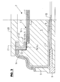
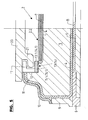
- Schnitte entsprechend den Linien I - I, II - II bzw. III - III der
Figur 1.
- Fig. 1
- in a simplified representation and in side view of a snow sliding board according to the invention in the form of a ski;
- Fig. 2
- in an enlarged partial view a plan view of the ski of Figure 1;
- Fig. 3 to 5
- Sections corresponding to the lines I - I, II - II and III - III of Figure 1.
In den Figuren ist 1 ein Ski mit einem Skikörper 2, der unter Verwendung der üblichen Skibaumaterialien und im wesentlichen in der üblichen Weise ausgebildet ist. Der Skikörper 2 besteht demnach beispielsweise aus dem inneren Kern 3 mit einem diesen Kern umgebenden Torsionskasten 4, aus der die Skikörperunterseite 2.1 bildenden Laufflächenbelag 5 mit den seitlichen Stahlkanten 6, aus dem Obergurt 7 oberhalb des Kernes 3 und dem Untergurt 8 zwischen Torsionskasten und Laufflächenbelag 5, aus den die Längsseiten des Skis bildenden Seitenwangen 9 und aus einer die Oberseite und teilweise auch die Längsseiten des Skikörpers 2 bildenden Dekor- und Abschlussfolie 10.In the figures, 1 is a ski with a
Bei der dargestellten Ausführungsform sind der Kern 3, der Torsionskasten 4 und z.B. auch der Obergurt 7 derart geformt, dass der Skikörper 2 an der Skikörperoberseite 2.2 zwei sich jeweils in Skikörperlängsrichtung erstreckende, parallel zueinander und voneinander beabstandete Vorsprünge 11 bildet, die sich z.B. über die gesamte oder nahezu die gesamte Länge des Skis oder über einen großteil der Skilänge erstrecken. An den einander zugewandten, innen liegenden Seiten 11.1 der Vorsprünge 11 sind in dortigen Ausnehmungen 12, die im mittleren Bereich des Skikörpers 2 bzw. im Bindungsbereich vorgesehen und jeweils zu dem jeweils andren Vorsprung sowie zur Oberseite des Skis 1 offen sind, Verbindungsstücke 13 und 14 eingesetzt, und zwar an jedem Vorsprung in einer Richtung vom rückwärtigen Ende 2.3 des Skikörpers 2 zum Schaufelbereich 2.2 dieses Skikörpers hin zunächst das Verbindungsstück 13 und dann in Skikörperlängsrichtung und von diesem beabstandet das weitere Verbindungsstück 14. Die Verbindungsstücke 13 und 14 sind bei der dargestellten Ausführungsform im wesentlichen leistenartige Formkörper 15 bzw. 16 aus Metall oder Kunststoff. Diese Formkörper sind jeweils mit einer an einer Verbindungsstücklängsseite 13.1 bzw. 14.1 offenen, an den beiden Enden des jeweiligen Verbindungsstückes 13 bzw. 14 jedoch geschlossenen Nut 17 ausgebildet und in geeigneter Weise, beispielsweise durch Verschrauben und/oder durch angeformte Zapfen und/oder durch Verkleben oder dergleichen in den Ausnehmungen 12 derart befestigt sind, dass sich die beiden Verbindungsstücke 13 senkrecht zur Skilängserstreckung mit der offenen Seite ihrer Nuten 17 paarweise unmittelbar gegenüber liegen, ebenso auch die beiden Verbindungsstücke 14.In the illustrated embodiment, the
Um durch die Verbindungsstücke 13 und 14, die mit ihrer Oberseite bündig mit der Oberseite des jeweiligen Vorsprungs liegen, also nicht über die Oberseite des Skikörpers oder der Vorsprünge vorstehen, die Flexibilität des Skikörpers 2 nicht oder nur geringfügig zu beeinträchtigen, sind diese jeweils segmentiert, d. h. mit senkrecht zu ihrer Längserstreckung verlaufenden nutenartigen Einschnitten 18 derart versehen, dass jedes Verbindungsstück 13 und 14 bzw. der entsprechende Formkörper 15 bzw. 16 insgesamt vier Segmente 15.1 - 15.4 bzw. 16.1 - 16.4 bildet. Diese sind lediglich über Materialabschnitte 15.5 bzw. 16.5 verbunden sind, welche bei montierten Verbindungsstücken sich an der der Skikörperunterseite 2.1 zugewandten unteren Begrenzung der jeweiligen Ausnehmung 12 befinden.To protrude through the connecting
Bei der dargestellten Ausführungsform besitzen die Verbindungsstücke 13 und 14 bzw. deren Formkörper 15 und 16 jeweils dieselbe Länge. Weiterhin ist jeder Formkörper durch die Einschnitte 18 in vier Segmente gleicher Länge unterteilt.In the illustrated embodiment, the connecting
An der Oberseite des Verbindungsstückes 13 bzw. an der Oberseite der Segmente 15.1 und 15.3 sind die Verbindungsstücke 13 jeweils mit einer Öffnung 19 versehen, die sich bei der dargestellten Ausführungsform über die gesamte Länge des betreffenden Segmentes erstreckt und von dem Öffnungsrand der Nut 17 bis an den Boden dieser Nut reicht. Über die Ausnehmungen 19 sind an der Unterseite eines Bindungselementes, beispielsweise an der Unterseite einer Bindungsplatte 20 vorgesehene Verriegelungsabschnitte 21 in jeweils eine Nut 17 des Verbindungsstückes 13 durch Aufsetzen von oben her einführbar wofür die Länge des Verriegelungselementes 21 in Längsrichtung der Bindungsplatte 20 bzw. Längsrichtung des Skis gleich oder geringfügig kleiner ist als die entsprechende Länge der Ausnehmungen 19. Durch Verschieben der Bindungsplatte 20 in Skilängsrichtung um die Länge eines Segmentes 15.1 - 15.4 ist die Bindungsplatte 20 dann mit ihren Verriegelungselementen 21 an den beiden Verbindungsstücken 13 und damit an der Skikörperoberseite 2.2 verankerbar. Bei der dargestellten Ausführungsform weist die Bindungsplatte 20 an ihrer Unterseite zwei Paare von leistenartigen Verriegelungselementen 21 auf.At the top of the connecting
Der Abstand, den die Verriegelungselemente 21 an jeder Längsseite der Bindungsplatte 20 voneinander aufweisen, ist dann ebenfalls gleich dem Abstand der Ausnehmungen 19 an den Verbindungsstücken 13. Bei der dargestellten Ausführungsform sind die Verriegelungsabschnitte 21 durch eine entsprechende Profilierung der Bindungsplatten 20 gebildet. Das rückwärtige Ende der Bindungsplatte 20 ist somit an jedem Verbindungsstück 13 zweifach, d. h. durch zweifachen Übergriff verankert. Im befestigten Zustand liegt die Bindungsplatte 20 mit ihren beiden Längsrändern auf der Oberseite der Vorsprünge 11 und auf der Oberseite der Verbindungsstücke 13 und 14 auf, so dass für eine optimale Kraftübertragung zwischen Bindung und Ski eine weit außen liegende Abstützung der Bindungsplatte 20 am Skikörper 2 erreicht ist.The distance between the
Im Bereich des rückwärtigen Endes der Bindungsplatte 20 ist das rückwärtige Bindungselement 22 in Skikörperlängsrichtung einstellbar vorgesehen, wie dies mit dem Doppelpfeil A angedeutet ist.In the region of the rear end of the
Die Verbindungsstücke 14 bzw. die entsprechenden Formteile 16 besitzen an ihrer Oberseite an dem in der Achsrichtung "Skikörperende 2.3 - Schaufel 2.4" ersten Segment 16.1 jeweils eine der Ausnehmung 19 entsprechende Ausnehmung 23. Die übrigen, jeweils in Richtung Skivorderseite bzw. in Richtung zum Schaufelbereich 2.4 anschließenden Segmente 16.2 - 16.4 besitzen die Ausnehmung 23 nicht. Mit dem vorderen Ende der Bindungsplatte 20 ist das vordere Bindungselement 24 (Bindungsvorderbacken) in Längsrichtung der Bindungsplatte 20 einstellbar befestigt (Doppelpfeil B). Das Bindungselement 24 ist an seiner Unterseite entsprechend der Bindungsplatte 20 ausgeführt, und zwar mit jeweils einem Verriegelungsabschnitt 21 an jeder Längsseite. Mit diesen Verbindungsabschnitten 21 ist dann das mit der Bindungsplatte 20 verbundene Bindungselement 24 über die Ausnehmungen 23 durch Aufsetzen in die Nut 17 der vorderen Verbindungsstücke 14 einführbar und dort beim axialen Verschieben der Bindungsplatte 20 verriegelbar. Da die Verbindungsstücke 14 mehrere, d. h. bei der dargestellten Ausführungsform insgesamt drei in Verbindungsstücklängsrichtung aneinander anschließende Segmente 16.2 - 16.4 ohne die Ausnehmung 23 aufweist, ist nach der Verriegelung des Bindungselementes 24 und damit auch des vorderen Endes der Bindungsplatte 20 an den Verbindungsstücken 14 bzw. am Skikörper 2 eine Längsverstellung (Doppelpfeil B) des Bindungselementes 24 relativ zur Bindungsplatte 20 unter Beibehaltung der Verriegelung am Skikörper 2 möglich. Die Ausbildung ist hierbei vorzugsweise so getroffen, dass das Einsetzen der Verriegelungsabschnitte 21 an der Bindungsplatte 20 und am vorderen Bindungselement 22 in die zugehörigen Ausnehmungen 19 bzw. 23 möglich ist, wenn sich das vordere Bindungselement 24 in einer der beiden Endstellungen seiner Verstellung (Doppelpfeil B) relativ zur Bindungsplatte 20 befindet, und zwar bei der dargestellten Ausführungsform in derjenigen Endstellung, in der das Bindungselement 22 der Basisplatte 20 am nächsten liegt.The connecting
Nach dem Einsetzen der Verriegelungsabschnitte 21 der Bindungsplatte 20 und des Bindungselementes 24 durch die Ausnehmungen 19 bzw. 23 in die Nut 17 der Verbindungsstücke 13 und 14 und nach dem Verriegeln durch Längsverschieben wird diese Verriegelung durch geeignete Mittel, beispielsweise durch ein Fixieren der Bindungsplatte 20 am Skikörper 2 mittels eines Stiftes oder dergleichen gesichert.After inserting the
Die Erfindung wurde voranstehend an einem Ausführungsbeispi'el beschrieben. Es versteht sich, dass Änderungen sowie Abwandlungen möglich sind, ohne dass dadurch der der Erfindung zu Grunde liegende Erfindungsgedanke verlassen wird.The invention has been described above with reference to an embodiment. It is understood that changes and modifications are possible without thereby departing from the inventive idea underlying the invention.
- 11
- Skiski
- 22
- Skikörperski body
- 2.12.1
- SkikörperunterseiteSkikörperunterseite
- 2.22.2
- SkikörperoberseiteSkikörperoberseite
- 2.32.3
- rückwärtiges Skikörperenderear ski body end
- 2.42.4
- Schaufelbereichblade area
- 33
- Kerncore
- 44
- Torsionskastentorsion
- 55
- LaufflächenbelagRunning surface
- 66
- Stahlkantesteel edge
- 77
- Obergurtupper chord
- 88th
- Untergurtlower chord
- 99
- SeitenwangenSidewall
- 1010
- Oberflächenfoliesurface sheet
- 1111
- Vorsprunghead Start
- 1212
- Ausnehmungrecess
- 13, 1413, 14
- Verbindungs- oder VerriegelungselementConnecting or locking element
- 15, 1615, 16
- Formkörpermoldings
- 15.1, 15.415.1, 15.4
- Segmentsegment
- 16.1 - 16.416.1 - 16.4
- Segmentsegment
- 15.5 - 16.515.5 - 16.5
- Materialabschnittmaterial section
- 1717
- Verriegelungsnutlocking
- 1818
- nutenförmiger Einschnittgroove-shaped incision
- 1919
- Ausnehmungrecess
- 2020
- Bindungsplattebinding plate
- 2121
- Verriegelungsabschnittlocking section
- 2222
- rückwärtiges Bindungselement (Bindungsbacken)rearward binding element (binding jaws)
- 2323
- Ausnehmungrecess
- 2424
- vorderes Bindungselement (Bindungsbacken)front binding element (binding jaws)
- A, BA, B
- Verstellmöglichkeitadjustment
Claims (10)
dass die Verbindungsstücke (13, 14) in einer Achsrichtung senkrecht zu ihrer Längserstreckung einander paarweise gegenüberliegend vorgesehen sind, und/oder
dass die Verriegelungsabschnitte (21) an der Bindung oder den Bindungselementen (20, 24) jeweils paarweise vorgesehen sind.Snow gliding board according to one of the preceding claims, characterized
in that the connecting pieces (13, 14) are provided in pairs opposite one another in an axial direction perpendicular to their longitudinal extent, and / or
in that the locking sections (21) are provided in pairs on the binding or the binding elements (20, 24).
dass die Verbindungsstücke (13, 14) Abstützflächen für die Bindung oder deren Elemente (20, 22, 24) bildet,
und/oder
dass sich die Bindung oder die Bindungselemente (20, 24) auf der Oberseite der Verbindungsstücke (13, 14) oder der diese Verbindungsstücke aufweisenden Vorsprünge (11) abstützt.Snow gliding board according to one of the preceding claims, characterized
in that the connecting pieces (13, 14) form supporting surfaces for the binding or their elements (20, 22, 24),
and or
in that the binding or the binding elements (20, 24) are supported on the upper side of the connecting pieces (13, 14) or on the projections (11) having these connecting pieces.
dass die Verbindungsstücke (13, 14) aus Metall und/oder Kunststoff gefertigt sind, und/oder
dass die Verbindungsstücke (13, 14) durch Befestigungselemente, beispielsweise Schrauben und/oder angeformte Dübel, und/oder durch Kleben am Schneegleitbrettkörper (2) gehalten sind.Snow gliding board according to one of the preceding claims, characterized
that the connecting pieces (13, 14) are made of metal and / or plastic, and or
in that the connecting pieces (13, 14) are held on the snow sliding board body (2) by fastening elements, for example screws and / or molded dowels, and / or by gluing.
Applications Claiming Priority (1)
| Application Number | Priority Date | Filing Date | Title |
|---|---|---|---|
| DE102004032386A DE102004032386A1 (en) | 2004-07-02 | 2004-07-02 | gliding over snow |
Publications (2)
| Publication Number | Publication Date |
|---|---|
| EP1611927A1 true EP1611927A1 (en) | 2006-01-04 |
| EP1611927B1 EP1611927B1 (en) | 2008-11-12 |
Family
ID=34937542
Family Applications (1)
| Application Number | Title | Priority Date | Filing Date |
|---|---|---|---|
| EP05013199A Not-in-force EP1611927B1 (en) | 2004-07-02 | 2005-06-18 | Snowglide board |
Country Status (4)
| Country | Link |
|---|---|
| US (1) | US7290784B2 (en) |
| EP (1) | EP1611927B1 (en) |
| AT (1) | ATE413907T1 (en) |
| DE (2) | DE102004032386A1 (en) |
Cited By (2)
| Publication number | Priority date | Publication date | Assignee | Title |
|---|---|---|---|---|
| EP1872836A2 (en) | 2006-06-30 | 2008-01-02 | Marker Völkl International GmbH | Snow glide board, in particular a ski, with interruption in the rails |
| EP2067506A1 (en) | 2007-12-07 | 2009-06-10 | Marker Völkl International GmbH | Snow glide board, in particular a ski, with fixing of the sliding element through pegs |
Families Citing this family (6)
| Publication number | Priority date | Publication date | Assignee | Title |
|---|---|---|---|---|
| WO2007067928A2 (en) * | 2005-12-06 | 2007-06-14 | K-2 Corporation | Ski binding system |
| FR2901486A1 (en) * | 2006-05-24 | 2007-11-30 | Salomon Sa | ASSEMBLY COMPRISING A SLIDING BOARD AND A DEVICE FOR RETAINING A FOOTWEAR ARTICLE ON THE BOARD |
| AT504840B1 (en) * | 2007-02-02 | 2009-07-15 | Atomic Austria Gmbh | SCHI OR SNOWBOARD IN THE SHAPE OF A BRETTY SLIDER |
| DE102008034293A1 (en) * | 2008-07-22 | 2010-01-28 | Marker Völkl (International) GmbH | Ski, especially downhill skiing |
| AT508022B1 (en) * | 2009-07-06 | 2010-10-15 | Atomic Austria Gmbh | BRETTY SLIDING DEVICE IN THE SHAPE OF A SCISSOR OR SNOWBOARD |
| US9305120B2 (en) | 2011-04-29 | 2016-04-05 | Bryan Marc Failing | Sports board configuration |
Citations (3)
| Publication number | Priority date | Publication date | Assignee | Title |
|---|---|---|---|---|
| EP0383104A2 (en) * | 1989-02-15 | 1990-08-22 | HTM Sport- und Freizeitgeräte Aktiengesellschaft | Ski |
| US5056809A (en) * | 1988-08-17 | 1991-10-15 | Salomon S.A. | Safety ski binding |
| WO2002049728A1 (en) * | 2000-12-19 | 2002-06-27 | Elan, D.D. | Ski or similar skating requisite with incorporated assembly for adjustable attaching a ski binding |
Family Cites Families (14)
| Publication number | Priority date | Publication date | Assignee | Title |
|---|---|---|---|---|
| US4008901A (en) * | 1975-06-11 | 1977-02-22 | Conn J L | Triple skate attachments |
| US5035443A (en) * | 1990-03-27 | 1991-07-30 | Kincheloe Chris V | Releasable snowboard binding |
| FR2684888B1 (en) * | 1991-12-13 | 1994-02-04 | Salomon Sa | INTERFACE PLATE FOR THE SLIDE OF A MOBILE ELEMENT, ESPECIALLY AN ALPINE FIXING ELEMENT. |
| US5520405A (en) * | 1994-08-10 | 1996-05-28 | Bourke; Lyle J. | Snowboard binding and boot including complementary opening and binding member |
| US5505478A (en) * | 1994-08-17 | 1996-04-09 | Napoliello; Michael | Releasable mounting for a snowboard binding |
| FR2734490B1 (en) * | 1995-05-22 | 1997-07-04 | Rossignol Sa | SNOW SLIDING BOARD COMPRISING A PLATFORM FOR RECEIVING AND RAISING SHOE MOUNTS |
| FR2734489B1 (en) * | 1995-05-22 | 1997-07-04 | Rossignol Sa | "HALF-SHELL" SNOWBOARD ON SNOW, PROVIDED WITH HULL SUPPORT EDGES |
| JP2000511079A (en) * | 1996-05-17 | 2000-08-29 | ブリガム ヤング ユニバーシティー | Improved binding assembly for snowboarding |
| FR2752528B1 (en) * | 1996-08-21 | 1998-11-27 | Porte Pierre Alain | DEVICE FOR FIXING THE FOOT ON A SPORTS MACHINE, OF THE SNOW SURFBOARD, SKATEBOARD OR SKATE TYPE, COMPOSED OF A BOOT AND A BASE ATTACHED TO THE SPORTS MACHINE |
| FR2786403B1 (en) * | 1998-11-27 | 2001-02-16 | Salomon Sa | SKI EQUIPPED WITH AN INTERFACE DEVICE PROVIDED FOR SUPPORTING SHOE RETAINING ELEMENTS |
| US20020113413A1 (en) * | 2001-02-16 | 2002-08-22 | Clifford Sosin | Transferable ski binding |
| US6557866B2 (en) * | 2001-03-09 | 2003-05-06 | Dennis Jones | Snowboard binding |
| AT414100B (en) * | 2002-10-28 | 2006-09-15 | Tyrolia Technology Gmbh | IN THE CONSTRUCTION OF A SLIDING BOARD, IN PARTICULAR A SKIS, INTEGRATED GUIDANCE AND SLIDING BOARD, IN PARTICULAR SKI |
| DE10254471A1 (en) * | 2002-11-21 | 2004-06-03 | Madsus A/S | Ski with binding assembly aid, process for producing such a ski and corresponding assembly aid |
-
2004
- 2004-07-02 DE DE102004032386A patent/DE102004032386A1/en not_active Withdrawn
-
2005
- 2005-06-18 EP EP05013199A patent/EP1611927B1/en not_active Not-in-force
- 2005-06-18 DE DE502005005935T patent/DE502005005935D1/en active Active
- 2005-06-18 AT AT05013199T patent/ATE413907T1/en active
- 2005-07-01 US US11/171,203 patent/US7290784B2/en not_active Expired - Fee Related
Patent Citations (3)
| Publication number | Priority date | Publication date | Assignee | Title |
|---|---|---|---|---|
| US5056809A (en) * | 1988-08-17 | 1991-10-15 | Salomon S.A. | Safety ski binding |
| EP0383104A2 (en) * | 1989-02-15 | 1990-08-22 | HTM Sport- und Freizeitgeräte Aktiengesellschaft | Ski |
| WO2002049728A1 (en) * | 2000-12-19 | 2002-06-27 | Elan, D.D. | Ski or similar skating requisite with incorporated assembly for adjustable attaching a ski binding |
Cited By (5)
| Publication number | Priority date | Publication date | Assignee | Title |
|---|---|---|---|---|
| EP1872836A2 (en) | 2006-06-30 | 2008-01-02 | Marker Völkl International GmbH | Snow glide board, in particular a ski, with interruption in the rails |
| EP1872836A3 (en) * | 2006-06-30 | 2008-11-19 | Marker Völkl International GmbH | Snow glide board, in particular a ski, with interruption in the rails |
| EP2368607A1 (en) | 2006-06-30 | 2011-09-28 | Marker Völkl International GmbH | Snow glide board, in particular a ski, with binding rails associated with a dampening system |
| EP2067506A1 (en) | 2007-12-07 | 2009-06-10 | Marker Völkl International GmbH | Snow glide board, in particular a ski, with fixing of the sliding element through pegs |
| US8770614B2 (en) | 2007-12-07 | 2014-07-08 | Marker Volkl (International) Gmbh | Snow glide board, in particular ski |
Also Published As
| Publication number | Publication date |
|---|---|
| EP1611927B1 (en) | 2008-11-12 |
| US7290784B2 (en) | 2007-11-06 |
| DE502005005935D1 (en) | 2008-12-24 |
| ATE413907T1 (en) | 2008-11-15 |
| DE102004032386A1 (en) | 2006-01-26 |
| US20060001237A1 (en) | 2006-01-05 |
Similar Documents
| Publication | Publication Date | Title |
|---|---|---|
| EP1611927B1 (en) | Snowglide board | |
| EP1161972B1 (en) | Glider, especially ski as well as a profile system for such a glider | |
| EP0956465B1 (en) | Chain link with insertable separating pins | |
| EP1492598B1 (en) | Ski binding, in particular for cross-country skiing | |
| EP1297869B1 (en) | Snow glider, especially a ski | |
| DE19633536C2 (en) | Snowboard | |
| DE60208249T2 (en) | Support plate for a snowboard | |
| DE4414065C1 (en) | Fastener for securing two toothed belt ends together | |
| DE4030214C2 (en) | Lateral guide device of a cross-country ski boot | |
| EP1563879B1 (en) | Gliding board, in particular ski | |
| DE3434804A1 (en) | Tread element for moving pavement or escalator | |
| EP1872836B1 (en) | Snow glide board, in particular a ski, with interruption in the rails | |
| EP1366785A1 (en) | Ski, method for mounting a skibinding on a ski and method for producing the same | |
| DE3530263A1 (en) | STEP ELEMENT FOR MOVING PLANE OR STAIR | |
| EP2067506B1 (en) | Snow glide board, in particular a ski, with fixing of the sliding element through pegs | |
| DE4402662A1 (en) | Binding plate arrangement for ski | |
| DE19707689C1 (en) | Cable bridging section with at least one cable-channel | |
| DE4402669A1 (en) | Ski with dampening sections for absorption of vibration energy | |
| CH672431A5 (en) | ||
| EP1163937A2 (en) | Elevating-plate | |
| DE10062884A1 (en) | Gliding board, especially skis | |
| DE10237765B4 (en) | Binding plate for a snow sliding board, especially skis and snow sliding board with such a binding plate | |
| EP2210650B1 (en) | Multi-section attachment board for attaching a ski binding to a ski | |
| WO2000072926A1 (en) | Snowboard | |
| CH670080A5 (en) | Tread element for moving pavement or escalator |
Legal Events
| Date | Code | Title | Description |
|---|---|---|---|
| PUAI | Public reference made under article 153(3) epc to a published international application that has entered the european phase |
Free format text: ORIGINAL CODE: 0009012 |
|
| AK | Designated contracting states |
Kind code of ref document: A1 Designated state(s): AT BE BG CH CY CZ DE DK EE ES FI FR GB GR HU IE IS IT LI LT LU MC NL PL PT RO SE SI SK TR |
|
| AX | Request for extension of the european patent |
Extension state: AL BA HR LV MK YU |
|
| RAP1 | Party data changed (applicant data changed or rights of an application transferred) |
Owner name: MARKER VOELKL INTERNATIONAL GMBH |
|
| 17P | Request for examination filed |
Effective date: 20060302 |
|
| AKX | Designation fees paid |
Designated state(s): AT CH DE FR IT LI |
|
| GRAP | Despatch of communication of intention to grant a patent |
Free format text: ORIGINAL CODE: EPIDOSNIGR1 |
|
| GRAS | Grant fee paid |
Free format text: ORIGINAL CODE: EPIDOSNIGR3 |
|
| GRAA | (expected) grant |
Free format text: ORIGINAL CODE: 0009210 |
|
| AK | Designated contracting states |
Kind code of ref document: B1 Designated state(s): AT CH DE FR IT LI |
|
| REG | Reference to a national code |
Ref country code: CH Ref legal event code: EP |
|
| REF | Corresponds to: |
Ref document number: 502005005935 Country of ref document: DE Date of ref document: 20081224 Kind code of ref document: P |
|
| REG | Reference to a national code |
Ref country code: CH Ref legal event code: NV Representative=s name: LUCHS & PARTNER PATENTANWAELTE |
|
| PLBE | No opposition filed within time limit |
Free format text: ORIGINAL CODE: 0009261 |
|
| STAA | Information on the status of an ep patent application or granted ep patent |
Free format text: STATUS: NO OPPOSITION FILED WITHIN TIME LIMIT |
|
| 26N | No opposition filed |
Effective date: 20090813 |
|
| REG | Reference to a national code |
Ref country code: DE Ref legal event code: R082 Ref document number: 502005005935 Country of ref document: DE Representative=s name: SCHWABE SANDMAIR MARX, DE Ref country code: DE Ref legal event code: R082 Ref document number: 502005005935 Country of ref document: DE Representative=s name: SCHWABE SANDMAIR MARX PATENTANWAELTE RECHTSANW, DE |
|
| REG | Reference to a national code |
Ref country code: FR Ref legal event code: PLFP Year of fee payment: 12 |
|
| REG | Reference to a national code |
Ref country code: FR Ref legal event code: PLFP Year of fee payment: 13 |
|
| REG | Reference to a national code |
Ref country code: FR Ref legal event code: PLFP Year of fee payment: 14 |
|
| PGFP | Annual fee paid to national office [announced via postgrant information from national office to epo] |
Ref country code: CH Payment date: 20180622 Year of fee payment: 14 |
|
| PGFP | Annual fee paid to national office [announced via postgrant information from national office to epo] |
Ref country code: AT Payment date: 20180619 Year of fee payment: 14 Ref country code: FR Payment date: 20180622 Year of fee payment: 14 |
|
| PGFP | Annual fee paid to national office [announced via postgrant information from national office to epo] |
Ref country code: IT Payment date: 20180629 Year of fee payment: 14 Ref country code: DE Payment date: 20180625 Year of fee payment: 14 |
|
| REG | Reference to a national code |
Ref country code: DE Ref legal event code: R119 Ref document number: 502005005935 Country of ref document: DE |
|
| REG | Reference to a national code |
Ref country code: CH Ref legal event code: PL |
|
| REG | Reference to a national code |
Ref country code: AT Ref legal event code: MM01 Ref document number: 413907 Country of ref document: AT Kind code of ref document: T Effective date: 20190618 |
|
| PG25 | Lapsed in a contracting state [announced via postgrant information from national office to epo] |
Ref country code: AT Free format text: LAPSE BECAUSE OF NON-PAYMENT OF DUE FEES Effective date: 20190618 Ref country code: DE Free format text: LAPSE BECAUSE OF NON-PAYMENT OF DUE FEES Effective date: 20200101 Ref country code: IT Free format text: LAPSE BECAUSE OF NON-PAYMENT OF DUE FEES Effective date: 20190618 |
|
| PG25 | Lapsed in a contracting state [announced via postgrant information from national office to epo] |
Ref country code: LI Free format text: LAPSE BECAUSE OF NON-PAYMENT OF DUE FEES Effective date: 20190630 Ref country code: CH Free format text: LAPSE BECAUSE OF NON-PAYMENT OF DUE FEES Effective date: 20190630 |
|
| PG25 | Lapsed in a contracting state [announced via postgrant information from national office to epo] |
Ref country code: FR Free format text: LAPSE BECAUSE OF NON-PAYMENT OF DUE FEES Effective date: 20190630 |