EP1069362A2 - Jonction rotative pour milieux alternés - Google Patents
Jonction rotative pour milieux alternés Download PDFInfo
- Publication number
- EP1069362A2 EP1069362A2 EP00113749A EP00113749A EP1069362A2 EP 1069362 A2 EP1069362 A2 EP 1069362A2 EP 00113749 A EP00113749 A EP 00113749A EP 00113749 A EP00113749 A EP 00113749A EP 1069362 A2 EP1069362 A2 EP 1069362A2
- Authority
- EP
- European Patent Office
- Prior art keywords
- machine part
- sealing surfaces
- seal
- rotary union
- lubricating medium
- Prior art date
- Legal status (The legal status is an assumption and is not a legal conclusion. Google has not performed a legal analysis and makes no representation as to the accuracy of the status listed.)
- Granted
Links
- 238000007789 sealing Methods 0.000 claims abstract description 84
- 230000001050 lubricating effect Effects 0.000 claims abstract description 60
- 238000005096 rolling process Methods 0.000 description 3
- 239000000919 ceramic Substances 0.000 description 1
- 229910010293 ceramic material Inorganic materials 0.000 description 1
- 239000002826 coolant Substances 0.000 description 1
- 239000000314 lubricant Substances 0.000 description 1
- 238000004519 manufacturing process Methods 0.000 description 1
- 239000000463 material Substances 0.000 description 1
- 239000002569 water oil cream Substances 0.000 description 1
Images

Classifications
-
- F—MECHANICAL ENGINEERING; LIGHTING; HEATING; WEAPONS; BLASTING
- F16—ENGINEERING ELEMENTS AND UNITS; GENERAL MEASURES FOR PRODUCING AND MAINTAINING EFFECTIVE FUNCTIONING OF MACHINES OR INSTALLATIONS; THERMAL INSULATION IN GENERAL
- F16C—SHAFTS; FLEXIBLE SHAFTS; ELEMENTS OR CRANKSHAFT MECHANISMS; ROTARY BODIES OTHER THAN GEARING ELEMENTS; BEARINGS
- F16C33/00—Parts of bearings; Special methods for making bearings or parts thereof
- F16C33/72—Sealings
- F16C33/76—Sealings of ball or roller bearings
-
- F—MECHANICAL ENGINEERING; LIGHTING; HEATING; WEAPONS; BLASTING
- F16—ENGINEERING ELEMENTS AND UNITS; GENERAL MEASURES FOR PRODUCING AND MAINTAINING EFFECTIVE FUNCTIONING OF MACHINES OR INSTALLATIONS; THERMAL INSULATION IN GENERAL
- F16L—PIPES; JOINTS OR FITTINGS FOR PIPES; SUPPORTS FOR PIPES, CABLES OR PROTECTIVE TUBING; MEANS FOR THERMAL INSULATION IN GENERAL
- F16L27/00—Adjustable joints; Joints allowing movement
- F16L27/08—Adjustable joints; Joints allowing movement allowing adjustment or movement only about the axis of one pipe
- F16L27/0804—Adjustable joints; Joints allowing movement allowing adjustment or movement only about the axis of one pipe the fluid passing axially from one joint element to another
- F16L27/0808—Adjustable joints; Joints allowing movement allowing adjustment or movement only about the axis of one pipe the fluid passing axially from one joint element to another the joint elements extending coaxially for some distance from their point of separation
- F16L27/0824—Adjustable joints; Joints allowing movement allowing adjustment or movement only about the axis of one pipe the fluid passing axially from one joint element to another the joint elements extending coaxially for some distance from their point of separation with ball or roller bearings
- F16L27/0828—Adjustable joints; Joints allowing movement allowing adjustment or movement only about the axis of one pipe the fluid passing axially from one joint element to another the joint elements extending coaxially for some distance from their point of separation with ball or roller bearings having radial bearings
-
- F—MECHANICAL ENGINEERING; LIGHTING; HEATING; WEAPONS; BLASTING
- F16—ENGINEERING ELEMENTS AND UNITS; GENERAL MEASURES FOR PRODUCING AND MAINTAINING EFFECTIVE FUNCTIONING OF MACHINES OR INSTALLATIONS; THERMAL INSULATION IN GENERAL
- F16L—PIPES; JOINTS OR FITTINGS FOR PIPES; SUPPORTS FOR PIPES, CABLES OR PROTECTIVE TUBING; MEANS FOR THERMAL INSULATION IN GENERAL
- F16L27/00—Adjustable joints; Joints allowing movement
- F16L27/08—Adjustable joints; Joints allowing movement allowing adjustment or movement only about the axis of one pipe
- F16L27/0804—Adjustable joints; Joints allowing movement allowing adjustment or movement only about the axis of one pipe the fluid passing axially from one joint element to another
- F16L27/0808—Adjustable joints; Joints allowing movement allowing adjustment or movement only about the axis of one pipe the fluid passing axially from one joint element to another the joint elements extending coaxially for some distance from their point of separation
- F16L27/0812—Adjustable joints; Joints allowing movement allowing adjustment or movement only about the axis of one pipe the fluid passing axially from one joint element to another the joint elements extending coaxially for some distance from their point of separation with slide bearings
- F16L27/082—Adjustable joints; Joints allowing movement allowing adjustment or movement only about the axis of one pipe the fluid passing axially from one joint element to another the joint elements extending coaxially for some distance from their point of separation with slide bearings having axial sealing
-
- F—MECHANICAL ENGINEERING; LIGHTING; HEATING; WEAPONS; BLASTING
- F16—ENGINEERING ELEMENTS AND UNITS; GENERAL MEASURES FOR PRODUCING AND MAINTAINING EFFECTIVE FUNCTIONING OF MACHINES OR INSTALLATIONS; THERMAL INSULATION IN GENERAL
- F16C—SHAFTS; FLEXIBLE SHAFTS; ELEMENTS OR CRANKSHAFT MECHANISMS; ROTARY BODIES OTHER THAN GEARING ELEMENTS; BEARINGS
- F16C2361/00—Apparatus or articles in engineering in general
-
- Y—GENERAL TAGGING OF NEW TECHNOLOGICAL DEVELOPMENTS; GENERAL TAGGING OF CROSS-SECTIONAL TECHNOLOGIES SPANNING OVER SEVERAL SECTIONS OF THE IPC; TECHNICAL SUBJECTS COVERED BY FORMER USPC CROSS-REFERENCE ART COLLECTIONS [XRACs] AND DIGESTS
- Y10—TECHNICAL SUBJECTS COVERED BY FORMER USPC
- Y10T—TECHNICAL SUBJECTS COVERED BY FORMER US CLASSIFICATION
- Y10T137/00—Fluid handling
- Y10T137/8593—Systems
- Y10T137/86268—With running joint between movable parts of system
Definitions
- the present invention relates to a rotating union for the alternating passage of a lubricating and a non-lubricating medium from a standing in one rotating machine part, with a first seal in the form of two sliding on each other arranged, flat, substantially circular sliding sealing surfaces, which essentially are arranged concentrically to the axis of rotation of the rotating machine part and the in Axial direction are at least so far apart that they are each other during the Do not touch the relative rotation of the rotating machine part.
- Such rotary unions also referred to as “dry run safe rotary unions” are already known. If a lubricating medium is supplied, the brought two flat sliding sealing surfaces into contact with each other, the lubricating Medium forms a lubricating film between the sealing surfaces sliding on one another, so that in this way it is ensured that even at high speeds no excessive Frictional heat is generated, which otherwise very quickly destroys the sliding sealing surfaces could lead.
- the sliding sealing surfaces must be moved apart in the axial direction if the rotating machine part rotates at a certain rotational speed without the lubricating medium is supplied.
- the dry running safety is obtained by the fact that the two flat sliding sealing surfaces are moved a little apart in the axial direction, the enlarging sealing gap must in any case be so large that it is also taken into account the possible component tolerances of the entire device on which the Rotating union is attached, does not come into contact with the sliding sealing surfaces, as long as the lubricating medium is not supplied.
- the object of the present invention to create a rotary union of the type mentioned, which despite the So-called dry-running safety, however, only minimal leakage losses even when passing through of a non-lubricating medium and even at high speeds of the rotating one Has machine part.
- This object is achieved in that in addition to the first, flat seal cylindrical seal is provided, the sealing surfaces of which with a narrow sealing gap concentrically arranged cylinder jacket surfaces are formed, the cylindrical seal in the direction of a potential leakage current between the flow passage the rotating union and the first seal is arranged.
- the cylindrical sealing surfaces can therefore be much narrower and smaller Tolerances are produced because with cylindrical surfaces with correspondingly small Very tight tolerances can be maintained.
- the axial Distance between flat sliding sealing surfaces through all related components the relative can be long, influenced, so that a much larger axial surfaces A safe distance must be maintained in order to make the rotating union safe to run dry.
- the radius the cylindrical surface is smaller than the inner diameter of the flat, ring-shaped Sliding sealing surfaces of the first seal. Because of the small radius of these cylindrical surfaces are also the relative speeds between the opposing ones Sealing surfaces smaller and even in the case of a light touch therefore only arise relatively little frictional heat.
- the outer cylinder surface of the second seal with the rotating machine part connected while the inner cylinder surface of the second Seal is connected to the standing machine part.
- the reverse configuration is also possible.
- the cylindrical sealing surfaces in such a way that the inner cylinder surface in the axial direction with the area of the first, flat Seal overlaps.
- the inner surface of the cylinder, which is located on a Sleeve is either with the standing or with the rotating machine part connected and the seal with the flat sealing surfaces includes this sleeve, one each the flat sealing surfaces are connected to the stationary or rotating machine part. that part of this sleeve which projects beyond the flat first seal in the axial direction or cylindrical wall forms the inner or outer sealing surface of the second seal.
- the flat sealing surfaces are resilient in contact with one another are biased. This means that the flat sliding sealing surfaces normally with one Touch well-defined pressure force, so that the rotating union for the supply of a lubricating medium is designed, while for the supply of non-lubricating media the sliding sealing surfaces are moved apart in the axial direction against the force of the spring have to. In many applications, this is the shorter work cycle.
- the respective sealing surfaces or these sealing surfaces are preferably direct or indirect supporting parts designed so that the flat sealing surfaces to an axial sealing gap width can be moved apart, at least ten times the radial sealing gap width between the cylinder jacket surfaces of the second seal.
- the radial sealing gap width of the cylinder jacket surfaces at most one tenth of the required minimum axial gap width of the first seal which are set for continuous operation in any case for dry running safety got to.
- the smaller radius of the cylinder surface compared to the flat sliding sealing surfaces and taking into account the axial flow path along the cylindrical sealing surfaces compared to the radial flow path between the planes Sliding sealing surfaces can be achieved by the aforementioned design that the leakage rate at Design according to the invention compared to the sole provision of the planes Seal with an enlarged sealing gap for dry running safety by at least one Factor 100 is reduced.
- a preferred embodiment of the invention has integrated in the rotating union Rolling bearings and a hollow shaft which is rotatably arranged in the rolling bearings and which with the outer cylinder surface is integrally connected.
- the cylindrical can be guided particularly precisely Sealing surfaces are achieved so that they can be manufactured with particularly tight tolerances, the radial sealing gap can therefore be made particularly narrow.
- sliding sealing surfaces With regard to the flat sliding sealing surfaces, an embodiment of the invention is preferred for which these sliding sealing surfaces are arranged on sliding sealing rings, each with the standing or rotating machine parts are firmly and tightly connectable.
- sliding sealing surfaces are often made of a special material, for example ceramics are made, this arrangement of the sliding sealing surfaces is on separate, but firm and tight with the associated parts connectable rings particularly useful.
- an embodiment of the invention is expedient, in which either the inner or the outer cylinder jacket of the second seal is flexible in the radial direction is mounted elastically.
- a radial is expedient for a gaseous or non-lubricating medium Feed opening provided on the rotary union according to the invention, while for the lubricating medium has an axial feed opening centrally at one end of the rotating union is provided, but these positions can also be easily interchanged.
- the media can be fed independently and without mutual interference in this case also provided in the preferred embodiment of the invention that the supply opening for gas or another non-lubricating medium and also the Feed opening for the lubricating medium against each other by check valves Outflow of this or the other medium secured against the feed direction are.
- the lubricating medium is axial and the non-lubricating one Medium are fed radially into a socket, which is not in the standing machine part is rotatably but axially slidably mounted and the sealing surfaces of the standing Machine part carries both the first and the second seal.
- a socket which is not in the standing machine part is rotatably but axially slidably mounted and the sealing surfaces of the standing Machine part carries both the first and the second seal.
- the axial supply of the lubricating medium on the axially movable sleeve Pressure is exerted, whereby both the check valve provided on this socket opens as well as the bush in the axial direction with its flat sliding sealing surface on the sliding sealing surface of the rotating machine part is pressed so that when the lubricating Automatically sets the desired narrow sealing gap.
- the bushing of the fixed bearing that carries the sliding sealing surfaces can be used Machine part also by a spring against the compressive force of the lubricating medium be biased so that, in the normal case, if there is no supply of the lubricating medium, the flat sliding sealing surfaces 4, 6 are moved apart and are not in contact with one another.
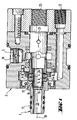
- FIG. 1 a housing 3 of a rotating union, which a standing Machine part corresponds or is connected to such. Furthermore one recognizes one rotatable machine part 1 with a hollow shaft 13 with a passage 20.
- the passage 20 is optionally with a radial feed opening 5 or an axial feed opening 25 connectable, each by check valves 19 and 21 against a backward flow and in particular are protected against backward flow of the other medium.
- the two mutually rotating machine parts 3 and 1 are above a first, radial Seal 7 and a second axial seal 17 in connection.
- the radial seal 7 is formed by two sliding disks or sliding rings 24, 26 with sliding sealing surfaces 4, 6 which lie in a radial plane of the rotating union.
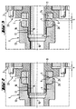
- the lubricating medium can then through the central through hole 20 in the direction flow to a point of consumption, by the pressure prevailing in the lubricating medium at the same time the check valve 19 in the supply opening for another, non-lubricating Medium kept closed.
- the lubricating medium can continue to flow through the radial sealing gap which is formed between the cylindrical surfaces 14 and 16, pass through and finally penetrates into the gap between the sliding sealing surfaces 4 and 6, in order to form a lubricating film there that also acts as a seal.
- a leakage space surrounds the mechanical seals 24, 26 so that the escaping medium is collected there and over the leak connection 12 shown only in Figure 2 can be removed.
- the exiting Leakage quantities are, however, very small due to this configuration of the seals.
- the pressure of the compressed air also causes the check valve 21 kept closed while the valve 19 is open due to this pressure.
- This compressed air can escape along the same leak path as the lubricating medium, in this case, however, the axial gap S between the sliding sealing surfaces 4 and 6 is much larger.
- the narrow radial gap between the cylinder jacket surfaces 14 and 16 provide sufficient flow resistance to compensate for the loss of compressed air would be sufficiently small and orders of magnitude less than this loss if the compressed air could escape directly through the axial gap between the surfaces 4 and 6.
- the radial sealing surface 16 is located on a hollow cylindrical extension of a sleeve 11, which is sealed and, as already mentioned, axially movable in the housing 3 of the rotating union is inserted.
- the cylinder jacket surface 14 is located at one end inside the passage 20 forming bore of the hollow shaft 13 and concentric to this bore. Otherwise, however the hollow shaft 13 may also be mounted so as to be axially movable, if appropriate between axial ones End stops in order to be able to actuate a tensioning device or the like:
- the remaining components shown serve essentially only as simple as possible Manufacture and assembly and need no further explanation here.
- an internal hexagon is designated within the bore of the hollow shaft 13 ', which Non-rotatable entrainment of an axially displaceable accommodated in the hollow shaft Tension rod causes.
- one more or less elastic storage of one of the sealing surfaces in the radial direction which makes a certain Compensation of tolerance deviation of the roundness of the surfaces 14, 16 can be achieved.
Landscapes
- Engineering & Computer Science (AREA)
- General Engineering & Computer Science (AREA)
- Mechanical Engineering (AREA)
- Joints Allowing Movement (AREA)
- Auxiliary Devices For Machine Tools (AREA)
Applications Claiming Priority (2)
| Application Number | Priority Date | Filing Date | Title |
|---|---|---|---|
| DE19932355A DE19932355B4 (de) | 1999-07-10 | 1999-07-10 | Drehdurchführung für wechselnde Medien |
| DE19932355 | 1999-07-10 |
Publications (3)
| Publication Number | Publication Date |
|---|---|
| EP1069362A2 true EP1069362A2 (fr) | 2001-01-17 |
| EP1069362A3 EP1069362A3 (fr) | 2003-10-01 |
| EP1069362B1 EP1069362B1 (fr) | 2006-02-08 |
Family
ID=7914384
Family Applications (1)
| Application Number | Title | Priority Date | Filing Date |
|---|---|---|---|
| EP00113749A Expired - Lifetime EP1069362B1 (fr) | 1999-07-10 | 2000-06-29 | Jonction rotative pour milieux alternés |
Country Status (7)
| Country | Link |
|---|---|
| US (1) | US6406065B1 (fr) |
| EP (1) | EP1069362B1 (fr) |
| JP (1) | JP4632489B2 (fr) |
| KR (1) | KR100769376B1 (fr) |
| CZ (1) | CZ296638B6 (fr) |
| DE (2) | DE19932355B4 (fr) |
| TW (1) | TW464742B (fr) |
Cited By (4)
| Publication number | Priority date | Publication date | Assignee | Title |
|---|---|---|---|---|
| EP2813740A3 (fr) * | 2013-06-11 | 2015-03-25 | Christian Maier GmbH & Co. KG Maschinenfabrik | Dispositif de transport de fluides |
| CN109127920A (zh) * | 2018-11-09 | 2019-01-04 | 重庆交通大学 | 气膜润滑导向装置及模具 |
| US11141577B2 (en) * | 2018-09-25 | 2021-10-12 | Megadyne Medical Products, Inc. | Fluid system connector |
| WO2023138727A1 (fr) * | 2022-01-18 | 2023-07-27 | Smets-Technology Gmbh | Traversée électrique rotative pour une boîte de vitesses |
Families Citing this family (29)
| Publication number | Priority date | Publication date | Assignee | Title |
|---|---|---|---|---|
| DE10135533B4 (de) * | 2001-07-20 | 2007-04-12 | Mosmatic Ag | Drehgelenk für Hochdruckvorrichtungen für die Verbindung eines nicht drehenden Teiles mit einem drehenden Teil |
| US6598502B1 (en) * | 2002-01-28 | 2003-07-29 | Titan Technologies International, Inc. | Multi-swivel connector for a fluid operated tool |
| NO316470B1 (no) * | 2002-05-08 | 2009-11-16 | Advanced Prod & Loading As | Anordning for sammenkopling av rørledninger som fører fluid under trykk |
| DE10225272B4 (de) | 2002-06-07 | 2005-05-04 | Ott-Jakob Gmbh & Co Spanntechnik Kg | Drehdurchführung |
| US7229102B2 (en) * | 2002-12-20 | 2007-06-12 | Deublin Company | Fluid coolant union |
| DE20305185U1 (de) | 2003-03-31 | 2003-05-28 | Deckel Maho Pfronten GmbH, 87459 Pfronten | Spindeleinheit für Werkzeugmaschinen |
| US7083200B2 (en) * | 2003-08-28 | 2006-08-01 | Focal Technologies Corporation | Fluid rotary union |
| DE10349968A1 (de) * | 2003-10-24 | 2005-05-25 | GAT Gesellschaft für Antriebstechnik mbH | Radiale Drehdurchführung |
| DE102004003459B4 (de) * | 2004-01-22 | 2009-07-02 | GAT Gesellschaft für Antriebstechnik mbH | Gleitringfixierung |
| FR2880669B1 (fr) * | 2005-01-07 | 2007-04-06 | Univ Limoges | Dispositif formant joint tournant pour conduits utilises en chimie analytique |
| JP5335180B2 (ja) * | 2005-05-17 | 2013-11-06 | デューブリン カンパニー | マルチ媒体回転ユニオン |
| DE102005038459A1 (de) * | 2005-08-13 | 2007-02-22 | Ott-Jakob Gmbh & Co. Spanntechnik Kg | Drehdurchführung mit Leckagesensor |
| DE102005052067A1 (de) * | 2005-10-28 | 2007-05-03 | Georg Springmann Industrie- Und Bergbautechnik Gmbh | Vorrichtung zum Ankuppeln einer Kühlmittelzuführung an eine Walze |
| AU2006326839B2 (en) | 2005-12-21 | 2012-05-24 | Taimi R & D Inc. | Self-lubricating swivelling coupling |
| US8307849B2 (en) * | 2008-06-03 | 2012-11-13 | Jergens, Inc. | Rotary coupler and method of using same |
| JP5221278B2 (ja) * | 2008-10-22 | 2013-06-26 | リックス株式会社 | ロータリジョイント |
| DE102009008425A1 (de) * | 2009-02-11 | 2010-09-16 | Mosmatic Ag | Drehdurchführung mit axialem Dichtring |
| US8453675B2 (en) * | 2009-12-01 | 2013-06-04 | Deublin Company | Rotary union with selectively controlled seal |
| WO2012129138A2 (fr) * | 2011-03-18 | 2012-09-27 | Cool Clean Technologies, Inc. | Procédé et appareil pour le contrôle thermique dans un procédé d'usinage |
| CA2822554A1 (fr) * | 2012-08-03 | 2014-02-03 | Deublin Company | Passage rotatif a actionneur de fermeture hermetique commande en pression |
| JP5998082B2 (ja) * | 2013-03-14 | 2016-09-28 | エヌティーツール株式会社 | 回転継手 |
| US9970577B2 (en) | 2013-09-27 | 2018-05-15 | The Procter & Gamble Company | Rotary union |
| JP6169993B2 (ja) * | 2014-03-11 | 2017-07-26 | 日本ピラー工業株式会社 | 清浄流体用ロータリジョイント |
| DE102016112470A1 (de) | 2016-07-07 | 2018-01-11 | GAT Gesellschaft für Antriebstechnik mbH | Pulverdrehdurchführung mit Spülkammer |
| US11278996B2 (en) | 2018-08-31 | 2022-03-22 | Deublin Company, LLC | Rotary seal |
| US11602815B2 (en) * | 2019-01-31 | 2023-03-14 | Fusion Coolant Systems, Inc. | Machining systems utilizing supercritical fluids |
| CN115218051B (zh) * | 2022-08-11 | 2024-02-02 | 温州金业气动科技有限公司 | 一种高速旋转接头 |
| WO2024214129A1 (fr) * | 2023-04-10 | 2024-10-17 | Dmg森精機株式会社 | Table |
| TWI897497B (zh) * | 2024-06-27 | 2025-09-11 | 富世達股份有限公司 | 液流接頭結構 |
Family Cites Families (29)
| Publication number | Priority date | Publication date | Assignee | Title |
|---|---|---|---|---|
| US2626166A (en) * | 1950-03-21 | 1953-01-20 | Fawick Airflex Company Inc | Plural-passage rotary fluid seal |
| US2727760A (en) * | 1950-10-07 | 1955-12-20 | Fawick Corp | High-speed rotary fluid seal |
| US3694008A (en) * | 1970-10-27 | 1972-09-26 | Bowen Tools Inc | Rotating joint |
| US3804424A (en) | 1972-04-24 | 1974-04-16 | Crane Packing Co | Gap seal with thermal and pressure distortion compensation |
| US3889983A (en) * | 1974-04-15 | 1975-06-17 | Duff Norton Co | Rotary fluid joint |
| JPS605168Y2 (ja) * | 1979-05-14 | 1985-02-16 | 日新製鋼株式会社 | オイルミストシ−ル |
| JPS6017306Y2 (ja) * | 1980-04-03 | 1985-05-28 | 東芝機械株式会社 | 溶融樹脂通路管の回転継手 |
| AT378037B (de) * | 1982-09-09 | 1985-06-10 | Voest Alpine Ag | Vorrichtung fuer die zufuehrung einer unter druck stehenden fluessigkeit zu einem rotierenden maschinenteil |
| US4669760A (en) * | 1986-02-05 | 1987-06-02 | Flow Industries, Inc. | Swivel fitting arrangement for use in a pressurized fluid line |
| US4848400A (en) * | 1988-02-19 | 1989-07-18 | Fsi International, Inc. | Rotary fluid coupling |
| DE3817799C1 (en) * | 1988-05-26 | 1989-11-30 | A. Ott Gmbh, 8960 Kempten, De | Rotary transmission leadthrough for fluids, in particular for machine-tool spindles |
| US4976282A (en) * | 1989-04-12 | 1990-12-11 | Deublin Company | Coolant union with fluid actuated seal assembly |
| JP2871082B2 (ja) * | 1990-11-29 | 1999-03-17 | ブラザー工業株式会社 | 流体供給継手 |
| DE4103376C1 (fr) * | 1991-02-05 | 1992-08-06 | Ott Maschinentechnik Gmbh, 8960 Kempten, De | |
| JPH051792A (ja) * | 1991-06-20 | 1993-01-08 | Honda Motor Co Ltd | ロータリジヨイント |
| US5226677A (en) * | 1991-08-09 | 1993-07-13 | The Johnson Corporation | Rotary joint with extended life seal |
| DE4210009C2 (de) * | 1992-03-27 | 1994-05-11 | Heidelberger Druckmasch Ag | Drehdurchführung |
| JPH05296376A (ja) * | 1992-04-20 | 1993-11-09 | Brother Ind Ltd | 流体供給用回転継手 |
| JP2906007B2 (ja) * | 1993-02-12 | 1999-06-14 | 株式会社牧野フライス製作所 | ロータリジョイント |
| JPH0826152A (ja) | 1994-07-19 | 1996-01-30 | Mitsubishi Agricult Mach Co Ltd | 作業車両用クローラガイドの仮止め機構 |
| JPH0826151A (ja) | 1994-07-19 | 1996-01-30 | Mitsubishi Heavy Ind Ltd | 車体屈折式ダンプトラックの運転席 |
| US5538292A (en) * | 1995-01-17 | 1996-07-23 | Midwest Brake Bond Company | Rotary union |
| US5669636A (en) * | 1995-08-01 | 1997-09-23 | Deublin Company | Floating seal assembly for a bearingless coolant union having air rotation capability |
| US5651567A (en) * | 1995-12-27 | 1997-07-29 | Kaleniecki; James F. | Multi-passage bearingless fluid coupler |
| JP3801677B2 (ja) * | 1996-01-19 | 2006-07-26 | リックス株式会社 | ロータリジョイント |
| JP3801676B2 (ja) * | 1996-01-19 | 2006-07-26 | リックス株式会社 | ロータリジョイント |
| US6109659C1 (en) * | 1998-06-12 | 2002-02-26 | Power Transmission Tech | Hydrostatic rotary union |
| US6203072B1 (en) * | 1999-08-30 | 2001-03-20 | The Johnson Corporation | Corrugating joint and syphon system |
| US6164316A (en) * | 1999-12-23 | 2000-12-26 | Deublin Company | High temperature rotating union |
-
1999
- 1999-07-10 DE DE19932355A patent/DE19932355B4/de not_active Expired - Fee Related
-
2000
- 2000-06-29 DE DE50012182T patent/DE50012182D1/de not_active Expired - Lifetime
- 2000-06-29 EP EP00113749A patent/EP1069362B1/fr not_active Expired - Lifetime
- 2000-07-04 CZ CZ20002534A patent/CZ296638B6/cs not_active IP Right Cessation
- 2000-07-05 KR KR1020000038312A patent/KR100769376B1/ko not_active Expired - Fee Related
- 2000-07-07 TW TW089113481A patent/TW464742B/zh not_active IP Right Cessation
- 2000-07-07 US US09/612,037 patent/US6406065B1/en not_active Expired - Fee Related
- 2000-07-10 JP JP2000207979A patent/JP4632489B2/ja not_active Expired - Fee Related
Cited By (4)
| Publication number | Priority date | Publication date | Assignee | Title |
|---|---|---|---|---|
| EP2813740A3 (fr) * | 2013-06-11 | 2015-03-25 | Christian Maier GmbH & Co. KG Maschinenfabrik | Dispositif de transport de fluides |
| US11141577B2 (en) * | 2018-09-25 | 2021-10-12 | Megadyne Medical Products, Inc. | Fluid system connector |
| CN109127920A (zh) * | 2018-11-09 | 2019-01-04 | 重庆交通大学 | 气膜润滑导向装置及模具 |
| WO2023138727A1 (fr) * | 2022-01-18 | 2023-07-27 | Smets-Technology Gmbh | Traversée électrique rotative pour une boîte de vitesses |
Also Published As
| Publication number | Publication date |
|---|---|
| CZ20002534A3 (cs) | 2001-02-14 |
| JP2001050451A (ja) | 2001-02-23 |
| US6406065B1 (en) | 2002-06-18 |
| DE50012182D1 (de) | 2006-04-20 |
| CZ296638B6 (cs) | 2006-05-17 |
| KR100769376B1 (ko) | 2007-10-22 |
| KR20010049718A (ko) | 2001-06-15 |
| JP4632489B2 (ja) | 2011-02-16 |
| EP1069362A3 (fr) | 2003-10-01 |
| DE19932355A1 (de) | 2001-01-25 |
| EP1069362B1 (fr) | 2006-02-08 |
| TW464742B (en) | 2001-11-21 |
| DE19932355B4 (de) | 2010-07-15 |
Similar Documents
| Publication | Publication Date | Title |
|---|---|---|
| EP1069362B1 (fr) | Jonction rotative pour milieux alternés | |
| DE69411227T2 (de) | Labyrinth-Gasdichtung | |
| DE3877762T2 (de) | Gleitring-dichtung mit zentriermitteln. | |
| DE3876985T2 (de) | Schraubenrotormaschine. | |
| DE19525343C2 (de) | Vorrichtung zum Überführen von Fluid zwischen relativ zueinander drehbaren Maschinenteilen | |
| DE3840487C2 (de) | Wellendichtungsanordnung | |
| EP2063156B1 (fr) | Arrangement d'étanchéité double | |
| DE102011050662B4 (de) | Walzwerkzeug | |
| DE3537740A1 (de) | Lagersystem | |
| DE69310494T2 (de) | Hochgeschwindigkeitsdrehverbindung | |
| EP1526316B1 (fr) | Passage radial tournant | |
| DE1944942A1 (de) | Schraubenverdichter und Verfahren zu seiner Verwendung | |
| EP0955123B1 (fr) | Dispositif pour le transfert d un fluide | |
| DE60300051T2 (de) | Wellendichtung | |
| EP0274090A2 (fr) | Dispositif d'étanchéité | |
| DE102004031350B4 (de) | Zwei-Wege-Drehdurchführung | |
| DE2710236C3 (de) | Schraubenpumpe | |
| DE2403173B2 (de) | Doppelgleitringdichtung | |
| EP2281135A1 (fr) | Passage tournant de grande capacité | |
| DE4019987C2 (de) | Drehdurchführung | |
| DE10017669A1 (de) | Gasgeschmierte Gleitringdichtung | |
| DE102010005537A1 (de) | Axial verspanntes Wälzlager | |
| EP1059475B1 (fr) | Garniture mécanique d'étanchéité | |
| DE102023211787B4 (de) | Elektromechanischer Aktuator mit Gleitkolben für verbesserte hydrodynamische Lagerung | |
| DE3008491A1 (de) | Gleitringdichtung |
Legal Events
| Date | Code | Title | Description |
|---|---|---|---|
| PUAI | Public reference made under article 153(3) epc to a published international application that has entered the european phase |
Free format text: ORIGINAL CODE: 0009012 |
|
| AK | Designated contracting states |
Kind code of ref document: A2 Designated state(s): AT BE CH CY DE DK ES FI FR GB GR IE IT LI LU MC NL PT SE |
|
| AX | Request for extension of the european patent |
Free format text: AL;LT;LV;MK;RO;SI |
|
| PUAL | Search report despatched |
Free format text: ORIGINAL CODE: 0009013 |
|
| AK | Designated contracting states |
Kind code of ref document: A3 Designated state(s): AT BE CH CY DE DK ES FI FR GB GR IE IT LI LU MC NL PT SE |
|
| AX | Request for extension of the european patent |
Extension state: AL LT LV MK RO SI |
|
| 17P | Request for examination filed |
Effective date: 20031216 |
|
| AKX | Designation fees paid |
Designated state(s): CH DE FR GB IT LI |
|
| GRAP | Despatch of communication of intention to grant a patent |
Free format text: ORIGINAL CODE: EPIDOSNIGR1 |
|
| GRAS | Grant fee paid |
Free format text: ORIGINAL CODE: EPIDOSNIGR3 |
|
| GRAA | (expected) grant |
Free format text: ORIGINAL CODE: 0009210 |
|
| AK | Designated contracting states |
Kind code of ref document: B1 Designated state(s): CH DE FR GB IT LI |
|
| REG | Reference to a national code |
Ref country code: GB Ref legal event code: FG4D Free format text: NOT ENGLISH |
|
| REG | Reference to a national code |
Ref country code: CH Ref legal event code: NV Representative=s name: AMMANN PATENTANWAELTE AG BERN Ref country code: CH Ref legal event code: EP |
|
| GBT | Gb: translation of ep patent filed (gb section 77(6)(a)/1977) |
Effective date: 20060208 |
|
| REF | Corresponds to: |
Ref document number: 50012182 Country of ref document: DE Date of ref document: 20060420 Kind code of ref document: P |
|
| PGFP | Annual fee paid to national office [announced via postgrant information from national office to epo] |
Ref country code: IT Payment date: 20060630 Year of fee payment: 7 |
|
| ET | Fr: translation filed | ||
| PLBE | No opposition filed within time limit |
Free format text: ORIGINAL CODE: 0009261 |
|
| STAA | Information on the status of an ep patent application or granted ep patent |
Free format text: STATUS: NO OPPOSITION FILED WITHIN TIME LIMIT |
|
| 26N | No opposition filed |
Effective date: 20061109 |
|
| PG25 | Lapsed in a contracting state [announced via postgrant information from national office to epo] |
Ref country code: IT Free format text: LAPSE BECAUSE OF NON-PAYMENT OF DUE FEES Effective date: 20070629 |
|
| REG | Reference to a national code |
Ref country code: FR Ref legal event code: ST Effective date: 20100226 |
|
| PG25 | Lapsed in a contracting state [announced via postgrant information from national office to epo] |
Ref country code: FR Free format text: LAPSE BECAUSE OF NON-PAYMENT OF DUE FEES Effective date: 20090630 |
|
| PGFP | Annual fee paid to national office [announced via postgrant information from national office to epo] |
Ref country code: FR Payment date: 20080424 Year of fee payment: 9 |
|
| PGFP | Annual fee paid to national office [announced via postgrant information from national office to epo] |
Ref country code: CH Payment date: 20120622 Year of fee payment: 13 |
|
| PGFP | Annual fee paid to national office [announced via postgrant information from national office to epo] |
Ref country code: GB Payment date: 20120622 Year of fee payment: 13 |
|
| PGFP | Annual fee paid to national office [announced via postgrant information from national office to epo] |
Ref country code: DE Payment date: 20130816 Year of fee payment: 14 |
|
| REG | Reference to a national code |
Ref country code: CH Ref legal event code: PL |
|
| GBPC | Gb: european patent ceased through non-payment of renewal fee |
Effective date: 20130629 |
|
| PG25 | Lapsed in a contracting state [announced via postgrant information from national office to epo] |
Ref country code: CH Free format text: LAPSE BECAUSE OF NON-PAYMENT OF DUE FEES Effective date: 20130630 Ref country code: GB Free format text: LAPSE BECAUSE OF NON-PAYMENT OF DUE FEES Effective date: 20130629 Ref country code: LI Free format text: LAPSE BECAUSE OF NON-PAYMENT OF DUE FEES Effective date: 20130630 |
|
| REG | Reference to a national code |
Ref country code: DE Ref legal event code: R119 Ref document number: 50012182 Country of ref document: DE |
|
| REG | Reference to a national code |
Ref country code: DE Ref legal event code: R119 Ref document number: 50012182 Country of ref document: DE Effective date: 20150101 |
|
| PG25 | Lapsed in a contracting state [announced via postgrant information from national office to epo] |
Ref country code: DE Free format text: LAPSE BECAUSE OF NON-PAYMENT OF DUE FEES Effective date: 20150101 |