EP1069362A2 - Rotatable connection for alternate mediums - Google Patents
Rotatable connection for alternate mediums Download PDFInfo
- Publication number
- EP1069362A2 EP1069362A2 EP00113749A EP00113749A EP1069362A2 EP 1069362 A2 EP1069362 A2 EP 1069362A2 EP 00113749 A EP00113749 A EP 00113749A EP 00113749 A EP00113749 A EP 00113749A EP 1069362 A2 EP1069362 A2 EP 1069362A2
- Authority
- EP
- European Patent Office
- Prior art keywords
- machine part
- sealing surfaces
- seal
- rotary union
- lubricating medium
- Prior art date
- Legal status (The legal status is an assumption and is not a legal conclusion. Google has not performed a legal analysis and makes no representation as to the accuracy of the status listed.)
- Granted
Links
- 238000007789 sealing Methods 0.000 claims abstract description 84
- 230000001050 lubricating effect Effects 0.000 claims abstract description 60
- 238000005096 rolling process Methods 0.000 description 3
- 239000000919 ceramic Substances 0.000 description 1
- 229910010293 ceramic material Inorganic materials 0.000 description 1
- 239000002826 coolant Substances 0.000 description 1
- 239000000314 lubricant Substances 0.000 description 1
- 238000004519 manufacturing process Methods 0.000 description 1
- 239000000463 material Substances 0.000 description 1
- 239000002569 water oil cream Substances 0.000 description 1
Images

Classifications
-
- F—MECHANICAL ENGINEERING; LIGHTING; HEATING; WEAPONS; BLASTING
- F16—ENGINEERING ELEMENTS AND UNITS; GENERAL MEASURES FOR PRODUCING AND MAINTAINING EFFECTIVE FUNCTIONING OF MACHINES OR INSTALLATIONS; THERMAL INSULATION IN GENERAL
- F16C—SHAFTS; FLEXIBLE SHAFTS; ELEMENTS OR CRANKSHAFT MECHANISMS; ROTARY BODIES OTHER THAN GEARING ELEMENTS; BEARINGS
- F16C33/00—Parts of bearings; Special methods for making bearings or parts thereof
- F16C33/72—Sealings
- F16C33/76—Sealings of ball or roller bearings
-
- F—MECHANICAL ENGINEERING; LIGHTING; HEATING; WEAPONS; BLASTING
- F16—ENGINEERING ELEMENTS AND UNITS; GENERAL MEASURES FOR PRODUCING AND MAINTAINING EFFECTIVE FUNCTIONING OF MACHINES OR INSTALLATIONS; THERMAL INSULATION IN GENERAL
- F16L—PIPES; JOINTS OR FITTINGS FOR PIPES; SUPPORTS FOR PIPES, CABLES OR PROTECTIVE TUBING; MEANS FOR THERMAL INSULATION IN GENERAL
- F16L27/00—Adjustable joints; Joints allowing movement
- F16L27/08—Adjustable joints; Joints allowing movement allowing adjustment or movement only about the axis of one pipe
- F16L27/0804—Adjustable joints; Joints allowing movement allowing adjustment or movement only about the axis of one pipe the fluid passing axially from one joint element to another
- F16L27/0808—Adjustable joints; Joints allowing movement allowing adjustment or movement only about the axis of one pipe the fluid passing axially from one joint element to another the joint elements extending coaxially for some distance from their point of separation
- F16L27/0824—Adjustable joints; Joints allowing movement allowing adjustment or movement only about the axis of one pipe the fluid passing axially from one joint element to another the joint elements extending coaxially for some distance from their point of separation with ball or roller bearings
- F16L27/0828—Adjustable joints; Joints allowing movement allowing adjustment or movement only about the axis of one pipe the fluid passing axially from one joint element to another the joint elements extending coaxially for some distance from their point of separation with ball or roller bearings having radial bearings
-
- F—MECHANICAL ENGINEERING; LIGHTING; HEATING; WEAPONS; BLASTING
- F16—ENGINEERING ELEMENTS AND UNITS; GENERAL MEASURES FOR PRODUCING AND MAINTAINING EFFECTIVE FUNCTIONING OF MACHINES OR INSTALLATIONS; THERMAL INSULATION IN GENERAL
- F16L—PIPES; JOINTS OR FITTINGS FOR PIPES; SUPPORTS FOR PIPES, CABLES OR PROTECTIVE TUBING; MEANS FOR THERMAL INSULATION IN GENERAL
- F16L27/00—Adjustable joints; Joints allowing movement
- F16L27/08—Adjustable joints; Joints allowing movement allowing adjustment or movement only about the axis of one pipe
- F16L27/0804—Adjustable joints; Joints allowing movement allowing adjustment or movement only about the axis of one pipe the fluid passing axially from one joint element to another
- F16L27/0808—Adjustable joints; Joints allowing movement allowing adjustment or movement only about the axis of one pipe the fluid passing axially from one joint element to another the joint elements extending coaxially for some distance from their point of separation
- F16L27/0812—Adjustable joints; Joints allowing movement allowing adjustment or movement only about the axis of one pipe the fluid passing axially from one joint element to another the joint elements extending coaxially for some distance from their point of separation with slide bearings
- F16L27/082—Adjustable joints; Joints allowing movement allowing adjustment or movement only about the axis of one pipe the fluid passing axially from one joint element to another the joint elements extending coaxially for some distance from their point of separation with slide bearings having axial sealing
-
- F—MECHANICAL ENGINEERING; LIGHTING; HEATING; WEAPONS; BLASTING
- F16—ENGINEERING ELEMENTS AND UNITS; GENERAL MEASURES FOR PRODUCING AND MAINTAINING EFFECTIVE FUNCTIONING OF MACHINES OR INSTALLATIONS; THERMAL INSULATION IN GENERAL
- F16C—SHAFTS; FLEXIBLE SHAFTS; ELEMENTS OR CRANKSHAFT MECHANISMS; ROTARY BODIES OTHER THAN GEARING ELEMENTS; BEARINGS
- F16C2361/00—Apparatus or articles in engineering in general
-
- Y—GENERAL TAGGING OF NEW TECHNOLOGICAL DEVELOPMENTS; GENERAL TAGGING OF CROSS-SECTIONAL TECHNOLOGIES SPANNING OVER SEVERAL SECTIONS OF THE IPC; TECHNICAL SUBJECTS COVERED BY FORMER USPC CROSS-REFERENCE ART COLLECTIONS [XRACs] AND DIGESTS
- Y10—TECHNICAL SUBJECTS COVERED BY FORMER USPC
- Y10T—TECHNICAL SUBJECTS COVERED BY FORMER US CLASSIFICATION
- Y10T137/00—Fluid handling
- Y10T137/8593—Systems
- Y10T137/86268—With running joint between movable parts of system
Definitions
- the present invention relates to a rotating union for the alternating passage of a lubricating and a non-lubricating medium from a standing in one rotating machine part, with a first seal in the form of two sliding on each other arranged, flat, substantially circular sliding sealing surfaces, which essentially are arranged concentrically to the axis of rotation of the rotating machine part and the in Axial direction are at least so far apart that they are each other during the Do not touch the relative rotation of the rotating machine part.
- Such rotary unions also referred to as “dry run safe rotary unions” are already known. If a lubricating medium is supplied, the brought two flat sliding sealing surfaces into contact with each other, the lubricating Medium forms a lubricating film between the sealing surfaces sliding on one another, so that in this way it is ensured that even at high speeds no excessive Frictional heat is generated, which otherwise very quickly destroys the sliding sealing surfaces could lead.
- the sliding sealing surfaces must be moved apart in the axial direction if the rotating machine part rotates at a certain rotational speed without the lubricating medium is supplied.
- the dry running safety is obtained by the fact that the two flat sliding sealing surfaces are moved a little apart in the axial direction, the enlarging sealing gap must in any case be so large that it is also taken into account the possible component tolerances of the entire device on which the Rotating union is attached, does not come into contact with the sliding sealing surfaces, as long as the lubricating medium is not supplied.
- the object of the present invention to create a rotary union of the type mentioned, which despite the So-called dry-running safety, however, only minimal leakage losses even when passing through of a non-lubricating medium and even at high speeds of the rotating one Has machine part.
- This object is achieved in that in addition to the first, flat seal cylindrical seal is provided, the sealing surfaces of which with a narrow sealing gap concentrically arranged cylinder jacket surfaces are formed, the cylindrical seal in the direction of a potential leakage current between the flow passage the rotating union and the first seal is arranged.
- the cylindrical sealing surfaces can therefore be much narrower and smaller Tolerances are produced because with cylindrical surfaces with correspondingly small Very tight tolerances can be maintained.
- the axial Distance between flat sliding sealing surfaces through all related components the relative can be long, influenced, so that a much larger axial surfaces A safe distance must be maintained in order to make the rotating union safe to run dry.
- the radius the cylindrical surface is smaller than the inner diameter of the flat, ring-shaped Sliding sealing surfaces of the first seal. Because of the small radius of these cylindrical surfaces are also the relative speeds between the opposing ones Sealing surfaces smaller and even in the case of a light touch therefore only arise relatively little frictional heat.
- the outer cylinder surface of the second seal with the rotating machine part connected while the inner cylinder surface of the second Seal is connected to the standing machine part.
- the reverse configuration is also possible.
- the cylindrical sealing surfaces in such a way that the inner cylinder surface in the axial direction with the area of the first, flat Seal overlaps.
- the inner surface of the cylinder, which is located on a Sleeve is either with the standing or with the rotating machine part connected and the seal with the flat sealing surfaces includes this sleeve, one each the flat sealing surfaces are connected to the stationary or rotating machine part. that part of this sleeve which projects beyond the flat first seal in the axial direction or cylindrical wall forms the inner or outer sealing surface of the second seal.
- the flat sealing surfaces are resilient in contact with one another are biased. This means that the flat sliding sealing surfaces normally with one Touch well-defined pressure force, so that the rotating union for the supply of a lubricating medium is designed, while for the supply of non-lubricating media the sliding sealing surfaces are moved apart in the axial direction against the force of the spring have to. In many applications, this is the shorter work cycle.
- the respective sealing surfaces or these sealing surfaces are preferably direct or indirect supporting parts designed so that the flat sealing surfaces to an axial sealing gap width can be moved apart, at least ten times the radial sealing gap width between the cylinder jacket surfaces of the second seal.
- the radial sealing gap width of the cylinder jacket surfaces at most one tenth of the required minimum axial gap width of the first seal which are set for continuous operation in any case for dry running safety got to.
- the smaller radius of the cylinder surface compared to the flat sliding sealing surfaces and taking into account the axial flow path along the cylindrical sealing surfaces compared to the radial flow path between the planes Sliding sealing surfaces can be achieved by the aforementioned design that the leakage rate at Design according to the invention compared to the sole provision of the planes Seal with an enlarged sealing gap for dry running safety by at least one Factor 100 is reduced.
- a preferred embodiment of the invention has integrated in the rotating union Rolling bearings and a hollow shaft which is rotatably arranged in the rolling bearings and which with the outer cylinder surface is integrally connected.
- the cylindrical can be guided particularly precisely Sealing surfaces are achieved so that they can be manufactured with particularly tight tolerances, the radial sealing gap can therefore be made particularly narrow.
- sliding sealing surfaces With regard to the flat sliding sealing surfaces, an embodiment of the invention is preferred for which these sliding sealing surfaces are arranged on sliding sealing rings, each with the standing or rotating machine parts are firmly and tightly connectable.
- sliding sealing surfaces are often made of a special material, for example ceramics are made, this arrangement of the sliding sealing surfaces is on separate, but firm and tight with the associated parts connectable rings particularly useful.
- an embodiment of the invention is expedient, in which either the inner or the outer cylinder jacket of the second seal is flexible in the radial direction is mounted elastically.
- a radial is expedient for a gaseous or non-lubricating medium Feed opening provided on the rotary union according to the invention, while for the lubricating medium has an axial feed opening centrally at one end of the rotating union is provided, but these positions can also be easily interchanged.
- the media can be fed independently and without mutual interference in this case also provided in the preferred embodiment of the invention that the supply opening for gas or another non-lubricating medium and also the Feed opening for the lubricating medium against each other by check valves Outflow of this or the other medium secured against the feed direction are.
- the lubricating medium is axial and the non-lubricating one Medium are fed radially into a socket, which is not in the standing machine part is rotatably but axially slidably mounted and the sealing surfaces of the standing Machine part carries both the first and the second seal.
- a socket which is not in the standing machine part is rotatably but axially slidably mounted and the sealing surfaces of the standing Machine part carries both the first and the second seal.
- the axial supply of the lubricating medium on the axially movable sleeve Pressure is exerted, whereby both the check valve provided on this socket opens as well as the bush in the axial direction with its flat sliding sealing surface on the sliding sealing surface of the rotating machine part is pressed so that when the lubricating Automatically sets the desired narrow sealing gap.
- the bushing of the fixed bearing that carries the sliding sealing surfaces can be used Machine part also by a spring against the compressive force of the lubricating medium be biased so that, in the normal case, if there is no supply of the lubricating medium, the flat sliding sealing surfaces 4, 6 are moved apart and are not in contact with one another.
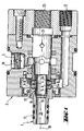
- FIG. 1 a housing 3 of a rotating union, which a standing Machine part corresponds or is connected to such. Furthermore one recognizes one rotatable machine part 1 with a hollow shaft 13 with a passage 20.
- the passage 20 is optionally with a radial feed opening 5 or an axial feed opening 25 connectable, each by check valves 19 and 21 against a backward flow and in particular are protected against backward flow of the other medium.
- the two mutually rotating machine parts 3 and 1 are above a first, radial Seal 7 and a second axial seal 17 in connection.
- the radial seal 7 is formed by two sliding disks or sliding rings 24, 26 with sliding sealing surfaces 4, 6 which lie in a radial plane of the rotating union.
- the lubricating medium can then through the central through hole 20 in the direction flow to a point of consumption, by the pressure prevailing in the lubricating medium at the same time the check valve 19 in the supply opening for another, non-lubricating Medium kept closed.
- the lubricating medium can continue to flow through the radial sealing gap which is formed between the cylindrical surfaces 14 and 16, pass through and finally penetrates into the gap between the sliding sealing surfaces 4 and 6, in order to form a lubricating film there that also acts as a seal.
- a leakage space surrounds the mechanical seals 24, 26 so that the escaping medium is collected there and over the leak connection 12 shown only in Figure 2 can be removed.
- the exiting Leakage quantities are, however, very small due to this configuration of the seals.
- the pressure of the compressed air also causes the check valve 21 kept closed while the valve 19 is open due to this pressure.
- This compressed air can escape along the same leak path as the lubricating medium, in this case, however, the axial gap S between the sliding sealing surfaces 4 and 6 is much larger.
- the narrow radial gap between the cylinder jacket surfaces 14 and 16 provide sufficient flow resistance to compensate for the loss of compressed air would be sufficiently small and orders of magnitude less than this loss if the compressed air could escape directly through the axial gap between the surfaces 4 and 6.
- the radial sealing surface 16 is located on a hollow cylindrical extension of a sleeve 11, which is sealed and, as already mentioned, axially movable in the housing 3 of the rotating union is inserted.
- the cylinder jacket surface 14 is located at one end inside the passage 20 forming bore of the hollow shaft 13 and concentric to this bore. Otherwise, however the hollow shaft 13 may also be mounted so as to be axially movable, if appropriate between axial ones End stops in order to be able to actuate a tensioning device or the like:
- the remaining components shown serve essentially only as simple as possible Manufacture and assembly and need no further explanation here.
- an internal hexagon is designated within the bore of the hollow shaft 13 ', which Non-rotatable entrainment of an axially displaceable accommodated in the hollow shaft Tension rod causes.
- one more or less elastic storage of one of the sealing surfaces in the radial direction which makes a certain Compensation of tolerance deviation of the roundness of the surfaces 14, 16 can be achieved.
Landscapes
- Engineering & Computer Science (AREA)
- General Engineering & Computer Science (AREA)
- Mechanical Engineering (AREA)
- Joints Allowing Movement (AREA)
- Auxiliary Devices For Machine Tools (AREA)
Abstract
Die vorliegende Erfindung betrifft eine Drehdurchführung für die wechselnde Hindurchführung
eines schmierenden und eines nicht-schmierenden Mediums von einem stehenden (3) in ein
drehendes Maschinenteil (1), mit einer ersten Dichtung (7) in Form zweier aufeinander gleitend
angeordneter, ebener, im wesentlichen kreisringförmiger Gleitdichtflächen (4, 6), die im
wesentlichen konzentrisch zu der Drehachse (10) des drehenden Maschinenteils (1)
angeordnet sind und die in axialer Richtung soweit auseinander bewegbar sind, daß sie
während der Drehung des drehenden Maschinenteils (1) nicht mehr miteinander in Kontakt
kommen. Um eine Drehdurchführung der eingangs genannten Art zu schaffen, die trotz der
sogenannten Trockenlaufsicherheit dennoch nur geringe Leckverluste auch bei der Hindurchführung
eines nicht-schmierenden Mediums und selbst bei hohen Drehzahlen des drehenden
Maschinenteils aufweist, wird erfindungsgemäß vorgeschlagen, daß eine zusätzliche
zylindrische Dichtung (17) vorgesehen ist, deren Dichtflächen von mit einem schmalen
Dichtspalt konzentrisch zueinander angeordneten Zylindermantelflächen (14, 16) gebildet
werden, wobei die zylindrische Dichtung (17) in Leckstromrichtung zwischen dem Strömungsdurchgang
(20) der Drehdurchführung und der ersten Dichtung (7) angeordnet ist.
Description
Die vorliegende Erfindung betrifft eine Drehdurchführung für die wechselnde Hindurchführung eines schmierenden und eines nicht-schmierenden Mediums von einem stehenden in ein drehendes Maschinenteil, mit einer ersten Dichtung in Form zweier aufeinander gleitend angeordneter, ebener, im wesentlichen kreisringförmiger Gleitdichtflächen, die im wesentlichen konzentrisch zu der Drehachse des drehenden Maschinenteils angeordnet sind und die in axialer Richtung mindestens so weit auseinander bewegbar sind, daß sie einander während der Relativdrehung des drehenden Maschinenteils nicht berühren.The present invention relates to a rotating union for the alternating passage of a lubricating and a non-lubricating medium from a standing in one rotating machine part, with a first seal in the form of two sliding on each other arranged, flat, substantially circular sliding sealing surfaces, which essentially are arranged concentrically to the axis of rotation of the rotating machine part and the in Axial direction are at least so far apart that they are each other during the Do not touch the relative rotation of the rotating machine part.
Solche Drehdurchführungen, die auch als "trockenlaufsichere Drehdurchführungen" bezeichnet werden, sind bereits bekannt. Wenn ein schmierendes Medium zugeführt wird, werden die beiden ebenen Gleitdichtflächen in Kontakt miteinander gebracht, wobei das schmierende Medium zwischen den aufeinander gleitenden Dichtflächen einen Schmierfilm bildet, so daß auf diese Weise sichergestellt wird, daß auch bei hohen Drehzahlen keine übermäßige Reibungswärme entsteht, die ansonsten sehr schnell zur Zerstörung der Gleitdichtflächen führen könnte. Such rotary unions, also referred to as "dry run safe rotary unions" are already known. If a lubricating medium is supplied, the brought two flat sliding sealing surfaces into contact with each other, the lubricating Medium forms a lubricating film between the sealing surfaces sliding on one another, so that in this way it is ensured that even at high speeds no excessive Frictional heat is generated, which otherwise very quickly destroys the sliding sealing surfaces could lead.
Allerdings müssen die Gleitdichtflächen in axialer Richtung auseinander bewegt werden, wenn sich das drehende Maschinenteil mit einer gewissen Rotationsgeschwindigkeit dreht, ohne daß das schmierende Medium zugeführt wird. In diesem Fall kann sich nämlich kein Schmierfilm zwischen den Gleitdichtflächen ausbilden und bei trocken aufeinander gleitenden Dichtflächen, die zumeist aus einem keramischen Material hergestellt sind, werden diese sehr schnell heiß und können dadurch zerstört werden, selbst wenn die Rotationsgeschwindigkeit des drehenden Maschinenteils vergleichsweise klein ist und weit unterhalb der Höchstdrehzahl liegt, für die die Dichtung für den Fall der Zuführung des schmierenden Mediums ausgelegt ist.However, the sliding sealing surfaces must be moved apart in the axial direction if the rotating machine part rotates at a certain rotational speed without the lubricating medium is supplied. In this case there is no lubricating film between the sliding sealing surfaces and with dry sliding surfaces, which are mostly made of a ceramic material, they get hot very quickly and can be destroyed even if the rotation speed of the rotating machine part is comparatively small and far below the maximum speed lies for which the seal is designed for the case of supply of the lubricating medium.
Die Trockenlaufsicherheit erhält man also dadurch, daß die beiden ebenen Gleitdichtflächen in axialer Richtung ein Stück weit auseinander bewegt werden, wobei der sich dabei vergrößernde Dichtspalt auf jeden Fall so groß sein muß, daß es auch unter Berücksichtigung der möglicherweise auftretenden Bauteiltoleranzen der gesamten Vorrichtung, an welcher die Drehdurchführung angebracht ist, nicht zu einer Berührung der Gleitdichtflächen kommt, solange das schmierende Medium nicht zugeführt wird.The dry running safety is obtained by the fact that the two flat sliding sealing surfaces are moved a little apart in the axial direction, the enlarging sealing gap must in any case be so large that it is also taken into account the possible component tolerances of the entire device on which the Rotating union is attached, does not come into contact with the sliding sealing surfaces, as long as the lubricating medium is not supplied.
Dabei gibt es eine Reihe von Anwendungsfällen, bei welchen während der Drehung des drehenden Maschinenteils auch ein anderes Medium zugeführt werden soll, welches keine Schmiereigenschaften hat. Beispielsweise kann an einer Werkzeugmaschine während einer ersten Arbeitsphase eine Wasser-Ölemulsion als Kühl- und Schmiermittel durch eine hohle Spindel zugeführt werden, deren eines Ende mit dem drehenden Teil der Drehdurchführung verbunden ist bzw. dieses drehende Teil darstellt, und während einer anderen Arbeitsphase kann zum Beispiel Druckluft zum Ausblasen eines Bohrlochs oder zum Freiblasen des Arbeitsbereichs eines Werkzeuges zugeführt werden, während sich das Werkzeug weiterhin dreht.There are a number of applications in which during the rotation of the another rotating medium should be fed to another medium, which none Has lubricating properties. For example, on a machine tool during a first phase of work a water-oil emulsion as a coolant and lubricant through a hollow Spindle are fed, one end of which with the rotating part of the rotating union connected or represents this rotating part, and during another work phase can, for example, compressed air to blow out a borehole or to blow out the Work area of a tool can be fed while the tool continues turns.
Der während der Zuführung dieses nicht-schmierenden Mediums bewußt vergrößerte Dichtspalt zur Schonung der Gleitdichtflächen hat dann allerdings den Nachteil, daß in ganz erheblichem Maße Druckluft durch diesen Dichtspalt entweichen kann, was nicht nur zu einem Druckabfall und damit zu einer geringeren Effektivität der an einen Arbeitsort zugeführten Druckluft führt, sondern zusätzlich auch einen erheblichen Enegieverlust bedeutet.The one that was deliberately enlarged during the feeding of this non-lubricating medium Sealing gap to protect the sliding sealing surfaces then has the disadvantage that in whole Significant amounts of compressed air can escape through this sealing gap, which is not only one Pressure drop and thus to a lower effectiveness of the supplied to a work place Compressed air leads, but also means a significant loss of energy.
Ausgehend von diesem Stand der Technik liegt der vorliegenden Erfindung die Aufgabe zugrunde, eine Drehdurchführung der eingangs genannten Art zu schaffen, die trotz der sogenannten Trockenlaufsicherheit dennoch nur geringe Leckverluste auch bei der Hindurchführung eines nicht-schmierenden Mediums und selbst bei hohen Drehzahlen des drehenden Maschinenteils aufweist.Based on this prior art, the object of the present invention to create a rotary union of the type mentioned, which despite the So-called dry-running safety, however, only minimal leakage losses even when passing through of a non-lubricating medium and even at high speeds of the rotating one Has machine part.
Diese Aufgabe wird dadurch gelöst, daß neben der ersten, ebenen Dichtung eine zusätzliche zylindrische Dichtung vorgesehen ist, deren Dichtflächen von mit einem schmalen Dichtspalt konzentrisch zueinander angeordneten Zylindermantelflächen gebildet werden, wobei die zylindrische Dichtung in Richtung eines potentiellen Leckstromes zwischen dem Strömungsdurchgang der Drehdurchführung und der ersten Dichtung angeordnet ist.This object is achieved in that in addition to the first, flat seal cylindrical seal is provided, the sealing surfaces of which with a narrow sealing gap concentrically arranged cylinder jacket surfaces are formed, the cylindrical seal in the direction of a potential leakage current between the flow passage the rotating union and the first seal is arranged.
Die vorstehend genannten Merkmale bewirken, daß das nicht-schmierende Medium, bevor es überhaupt durch den vergrößerten axialen Spalt der ebenen Dichtung hindurchtreten kann, durch die von Zylindermantelflächen gebildete Dichtung und den dazwischen ausgebildeten schmalen Dichtspalt hindurchtreten muß, der allerdings wesentlich enger und kleiner gehalten werden kann als der axiale Spalt zwischen den ebenen Gleitdichflächen im Falle der Zuführung eines nicht-schmierenden Mediums.The foregoing features cause the non-lubricating medium to rise before it can even pass through the enlarged axial gap of the flat seal, through the seal formed by cylindrical surface areas and the one formed between them must pass through a narrow sealing gap, which, however, is kept much narrower and smaller can be considered as the axial gap between the plane sliding sealing surfaces in the case of the feed a non-lubricating medium.
Die zylindrischen Dichtflächen können deshalb mit wesentlich engeren und kleineren Toleranzen hergestellt werden, weil bei zylindrischen Flächen mit entsprechend kleinen Durchmessern sehr enge Toleranzen eingehalten werden können. Dagegen wird der axiale Abstand zwischen ebenen Gleitdichtflächen durch alle damit verbundenen Bauteile, die relativ lang sein können, beeinflußt, so daß bei den axialen Flächen ein wesentlich größerer Sicherheitsabstand einzuhalten ist, um die Drehdurchführung trockenlaufsicher zu machen. Hinzu kommt daß, jedenfalls in der bevorzugten Ausführungsform der Erfindung, der Radius der Zylindermantelflächen kleiner ist als der Innendurchmesser der ebenen, ringförmigen Gleitdichtflächen der ersten Dichtung. Wegen des geringen Radius dieser Zylindermantelflächen sind auch die Relativgeschwindigkeiten zwischen den einander gegenüberliegenden Dichtflächen kleiner und selbst im Fall einer leichten Berührung entsteht daher nur relativ wenig Reibungswärme.The cylindrical sealing surfaces can therefore be much narrower and smaller Tolerances are produced because with cylindrical surfaces with correspondingly small Very tight tolerances can be maintained. In contrast, the axial Distance between flat sliding sealing surfaces through all related components, the relative can be long, influenced, so that a much larger axial surfaces A safe distance must be maintained in order to make the rotating union safe to run dry. In addition, at least in the preferred embodiment of the invention, the radius the cylindrical surface is smaller than the inner diameter of the flat, ring-shaped Sliding sealing surfaces of the first seal. Because of the small radius of these cylindrical surfaces are also the relative speeds between the opposing ones Sealing surfaces smaller and even in the case of a light touch therefore only arise relatively little frictional heat.
Auf diese Weise kann man sicherstellen, daß auch ein Medium mit sehr niedriger Viskosität, wie zum Beispiel Druckluft, mit einer nur sehr geringen Leckrate durch die Drehdurchführung hindurchgeführt werden kann, selbst wenn sich das drehende Maschinenteil mit hohen Drehzahlen von zum Beispiel 20.000 Umdrehungen/Minute relativ zu dem stehenden Maschinenteil dreht.In this way you can ensure that a medium with very low viscosity, such as compressed air, with a very low leakage rate due to the rotating union can be passed through, even if the rotating machine part with high Speeds of, for example, 20,000 revolutions / minute relative to the stationary one Machine part turns.
Wenn das schmierende Medium zugeführt wird, so dringt dieses selbstverständlich ebenfalls in den schmalen radialen Dichtspalt zwischen den zylindrischen Dichtflächen ein und von dort auch in den axialen Spalt zwischen den ebenen Gleitdichtflächen, wobei in diesem Fall jedoch die Gleitflächen aneinander gedrückt werden und damit den Dichtspalt praktisch auf die Dicke des Schmierfilmes reduzieren, der aus dem schmierenden Medium entsteht.If the lubricating medium is supplied, this of course also penetrates in and out of the narrow radial sealing gap between the cylindrical sealing surfaces also in the axial gap between the flat sliding sealing surfaces, but in this case the sliding surfaces are pressed against each other and thus the sealing gap practically to the thickness reduce the lubricating film that is created from the lubricating medium.
Zweckmäßigerweise ist die äußere Zylindermantelfläche der zweiten Dichtung mit dem drehenden Maschinenteil verbunden, während die innere Zylindermantelfläche der zweiten Dichtung mit dem stehenden Maschinenteil verbunden ist. Selbstverständlich ist im Prinzip auch die umgekehrte Ausgestaltung möglich.Advantageously, the outer cylinder surface of the second seal with the rotating machine part connected, while the inner cylinder surface of the second Seal is connected to the standing machine part. In principle, of course the reverse configuration is also possible.
In jedem Fall ist es jedoch zweckmäßig, die zylindrischen Dichtflächen derart anzuordnen, daß die innere Zylindermantelfläche in axialer Richtung mit dem Bereich der ersten, ebenen Dichtung überlappt. Mit anderen Worten, die innere Zylindermantelfläche, die sich an einer Hülse befindet, ist entweder mit dem stehenden oder mit dem drehenden Maschinenteil verbunden und die Dichtung mit den ebenen Dichtflächen umfaßt diese Hülse, wobei je eine der ebenen Dichtflächen mit dem stehenden bzw. drehenden Maschinenteil verbunden ist. der über die ebene erste Dichtung in axialer Richtung hinausragende Teil dieser Hülse bzw. zylindrischen Wand bildet die innere oder äußere Dichtfläche der zweiten Dichtung.In any case, however, it is expedient to arrange the cylindrical sealing surfaces in such a way that the inner cylinder surface in the axial direction with the area of the first, flat Seal overlaps. In other words, the inner surface of the cylinder, which is located on a Sleeve is either with the standing or with the rotating machine part connected and the seal with the flat sealing surfaces includes this sleeve, one each the flat sealing surfaces are connected to the stationary or rotating machine part. that part of this sleeve which projects beyond the flat first seal in the axial direction or cylindrical wall forms the inner or outer sealing surface of the second seal.
Zweckmäßig ist es außerdem, wenn die ebenen Dichtflächen in Anlage miteinander federnd vorgespannt sind. Dies bedeutet, daß sich die ebenen Gleitdichtflächen im Normalfall mit einer wohldefinierten Andruckkraft berühren, so daß die Drehdurchführung für die Zufuhr eines schmierenden Mediums ausgelegt ist, während für die Zuführung nicht-schmierender Medien die Gleitdichtflächen gegen die Kraft der Feder in axialer Richtung auseinander bewegt werden müssen. Dies ist bei vielen Anwendungsfällen der kürzere Arbeitstakt.It is also expedient if the flat sealing surfaces are resilient in contact with one another are biased. This means that the flat sliding sealing surfaces normally with one Touch well-defined pressure force, so that the rotating union for the supply of a lubricating medium is designed, while for the supply of non-lubricating media the sliding sealing surfaces are moved apart in the axial direction against the force of the spring have to. In many applications, this is the shorter work cycle.
Vorzugsweise sind die jeweiligen Dichtflächen bzw die diese Dichtflächen direkt oder indirekt tragenden Teile so ausgestaltet, daß die ebenen Dichtflächen zu einer axialen Dichtspaltbreite auseinander bewegt werden können, die mindestens das Zehnfache der radialen Dichtspaltbreite zwischen den Zylindermantelflächen der zweiten Dichtung beträgt.The respective sealing surfaces or these sealing surfaces are preferably direct or indirect supporting parts designed so that the flat sealing surfaces to an axial sealing gap width can be moved apart, at least ten times the radial sealing gap width between the cylinder jacket surfaces of the second seal.
Umgekehrt könnte man auch sagen, daß die radiale Dichtspaltbreite der Zylindermantelflächen höchstens ein Zehntel der erforderlichen axialen Mindestspaltbreite der ersten Dichtung beträgt, die für die Trockenlaufsicherheit jedenfalls für den Dauerbetrieb eingestellt werden muß. Unter Berücksichtigung des kleineren Radius der Zylindermantelflächen gegenüber den ebenen Gleitdichtflächen und unter Berücksichtigung des axialen Strömungsweges entlang der zylindrischen Dichtflächen im Vergleich zu dem radialen Strömungsweg zwischen den ebenen Gleitdichtflächen erreicht man durch die vorgenannte Ausgestaltung, daß die Leckrate bei der erfindungsgemäßen Ausgestaltung im Vergleich zu dem alleinigen Vorsehen der ebenen Dichtung mit einem vergrößerten Dichtspalt zur Trockenlaufsicherheit um mindestens einen Faktor 100 vermindert wird.Conversely, one could also say that the radial sealing gap width of the cylinder jacket surfaces at most one tenth of the required minimum axial gap width of the first seal which are set for continuous operation in any case for dry running safety got to. Taking into account the smaller radius of the cylinder surface compared to the flat sliding sealing surfaces and taking into account the axial flow path along the cylindrical sealing surfaces compared to the radial flow path between the planes Sliding sealing surfaces can be achieved by the aforementioned design that the leakage rate at Design according to the invention compared to the sole provision of the planes Seal with an enlarged sealing gap for dry running safety by at least one Factor 100 is reduced.
Eine bevorzugte Ausführungsform der Erfindung hat in die Drehdurchführung integrierte Wälzlager und eine Hohlwelle, die in den Wälzlagern drehbar angeordnet ist und die mit der äußere Zylindermantelfläche einstückig verbunden ist.A preferred embodiment of the invention has integrated in the rotating union Rolling bearings and a hollow shaft which is rotatably arranged in the rolling bearings and which with the outer cylinder surface is integrally connected.
Bei dieser Ausführungsform kann eine besonders exakte Führung der zylindrischen Dichtflächen erreicht werden, so daß diese mit besonders engen Toleranzen herstellbar sind, der radiale Dichtspalt also besonders schmal gemacht werden kann.In this embodiment, the cylindrical can be guided particularly precisely Sealing surfaces are achieved so that they can be manufactured with particularly tight tolerances, the radial sealing gap can therefore be made particularly narrow.
Bezüglich der ebenen Gleitdichtflächen ist eine Ausgestaltung der Erfindung bevorzugt, bei welcher diese Gleitdichtflächen an Gleitdichtringen angeordnet sind, die jeweils mit dem stehenden bzw. dem drehenden Maschinenteil fest und dicht verbindbar sind.With regard to the flat sliding sealing surfaces, an embodiment of the invention is preferred for which these sliding sealing surfaces are arranged on sliding sealing rings, each with the standing or rotating machine parts are firmly and tightly connectable.
Da die Gleitdichtflächen oftmals aus einem besonderen Material, zum Beispiel aus Keramiken hergestellt sind, ist diese Anordnung der Gleitdichtflächen an getrennten, aber fest und dicht mit den zugeordneten Teilen verbindbaren Ringen besonders zweckmäßig.Because the sliding sealing surfaces are often made of a special material, for example ceramics are made, this arrangement of the sliding sealing surfaces is on separate, but firm and tight with the associated parts connectable rings particularly useful.
Weiterhin ist eine Ausführungsform der Erfindung zweckmäßig, bei welcher entweder der innere oder der äußere Zylindermantel der zweiten Dichtung in radialer Richtung nachgiebig elastisch gelagert ist. Hierdurch können geringe Toleranzabweichungen und Unrundheiten der einander gegenüberliegenden Dichtflächen leicht ausgeglichen werden, ohne daß es zu einer übermäßigen oder nennenswerten Reibung und einem Verschleiß der zylindrischen Flächen kommt.Furthermore, an embodiment of the invention is expedient, in which either the the inner or the outer cylinder jacket of the second seal is flexible in the radial direction is mounted elastically. As a result, small tolerance deviations and out-of-roundness of the mutually opposing sealing surfaces can be easily compensated for without causing a excessive or significant friction and wear of the cylindrical surfaces is coming.
Zweckmäßigerweise ist für ein gasförmiges bzw. nicht-schmierendes Medium eine radiale Zuführöffnung an der erfindungsgemäßen Drehdurchführung vorgesehen, während für das schmierende Medium eine axiale Zufuhröffnung zentral an einem Ende der Drehdurchführung vorgesehen ist, wobei aber diese Positionen auch ohne weiteres vertauscht werden können.A radial is expedient for a gaseous or non-lubricating medium Feed opening provided on the rotary union according to the invention, while for the lubricating medium has an axial feed opening centrally at one end of the rotating union is provided, but these positions can also be easily interchanged.
Damit die Zufuhr der Medien unabhängig und ohne wechselseitige Störung erfolgen kann, ist in diesem Fall außerdem in der bevorzugten Ausführungsform der Erfindung vorgesehen, daß die Zufuhröffnung für Gas bzw. ein anderes nicht-schmierendes Medium und auch die Zufuhröffnung für das schmierende Medium jeweils durch Rückschlagventile gegen ein Ausströmen dieses oder des jeweils anderen Mediums entgegen der Zuführrichtung gesichert sind.So that the media can be fed independently and without mutual interference in this case also provided in the preferred embodiment of the invention that the supply opening for gas or another non-lubricating medium and also the Feed opening for the lubricating medium against each other by check valves Outflow of this or the other medium secured against the feed direction are.
Zweckmäßig ist es außerdem, wenn das schmierende Medium axial und das nicht-schmierende Medium radial in eine Buchse zugeführt werden, die in dem stehenden Maschinenteil nicht drehbar, aber axial verschiebbar gelagert ist und die die Dichtflächen des stehenden Maschinenteils sowohl der ersten als auch der zweiten Dichtung trägt. Bei dieser Ausführungsform wird bei der axialen Zuführung des schmierenden Mediums auf die axial bewegliche Hülse Druck ausgeübt, wodurch sowohl das an dieser Buchse vorgesehene Rückschlagventil öffnet als auch die Buchse in axialer Richtung mit ihrer ebenen Gleitdichtfläche an die Gleitdichtfläche des rotierenden Maschinenteils angedrückt wird, so daß sich bei Zufuhr des schmierenden Mittels automatisch der gewünschte, schmale Dichtspalt einstellt. Wird die Zufuhr des schmierenden Mediums gestoppt, so daß auch der Druck auf die Buchse in axialer Richtung nachläßt und wird stattdessen durch die radiale Zufuhröffnung der Buchse das nichtschmierende Medium zugeführt, so öffnet dessen Druck nicht nur das zweite Rückschlagventil, sondern beaufschlagt auch das erstgenannte Rückschlagventil axial in der entgegengesetzten Richtung zum schmierenden Medium, wodurch die Buchse axial zurückbewegt wird und die beiden ebenen Gleitdichtflächen dadurch auseinanderbewegt werden. Auf diese Weise wird die gewünschte Stellung der Dichflächen automatisch durch die jeweils wechselnde Zufuhr des schmierenden bzw. des nicht-schmierenden Mediums eingestellt.It is also expedient if the lubricating medium is axial and the non-lubricating one Medium are fed radially into a socket, which is not in the standing machine part is rotatably but axially slidably mounted and the sealing surfaces of the standing Machine part carries both the first and the second seal. In this embodiment is the axial supply of the lubricating medium on the axially movable sleeve Pressure is exerted, whereby both the check valve provided on this socket opens as well as the bush in the axial direction with its flat sliding sealing surface on the sliding sealing surface of the rotating machine part is pressed so that when the lubricating Automatically sets the desired narrow sealing gap. Will the supply of the lubricating medium stopped, so that the pressure on the bushing in the axial direction subsides and instead becomes non-lubricating through the radial feed opening of the bushing Medium is supplied, its pressure not only opens the second check valve, but also acts axially on the first-mentioned check valve in the opposite Direction to the lubricating medium, which axially moves the bush back and the both flat sliding sealing surfaces can be moved apart. That way the desired position of the sealing surfaces automatically through the changing feed of the lubricating or non-lubricating medium.
Wenn allerdings die Drehdurchführung auch ohne Zufuhr irgendeines der beiden Medien
genutzt werden soll, so kann die die Gleitdichtflächen tragende Buchse des feststehenden
Maschinenteils auch durch eine Feder entgegen der Druckkraft des schmierenden Mediums
vorgespannt sein, so daß im Normalfall, bei ausbleibender Zufuhr des schmierenden Medium,
die ebenen Gleitdichtflächen 4, 6 auseinanderbewegt und nicht in Kontakt miteinander sind.If, however, the rotating union also without feeding any of the two media
to be used, the bushing of the fixed bearing that carries the sliding sealing surfaces can be used
Machine part also by a spring against the compressive force of the lubricating medium
be biased so that, in the normal case, if there is no supply of the lubricating medium,
the flat sliding
Weitere Vorteile, Merkmale und Anwendungsmöglichkeiten der vorliegenden Erfindung werden deutlich anhand der folgenden Beschreibung einer bevorzugten Ausführungsform und der dazugehörigen Figuren. Es zeigen:
Figur 1- einen axialen Längsschnitt durch eine erfindungsgemäße Drehdurchführung und
Figur 2- einen vergrößerten Ausschnitt der die Dichtflächen tragenden Bereiche bei Zufuhr eines schmierenden Mediums,
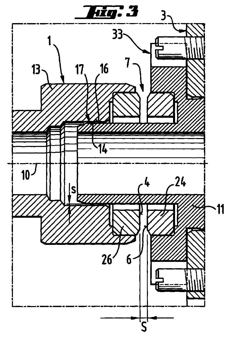
Figur 3- denselben Ausschnitt wie
Figur 2,jedoch bei Zufuhr eines nicht-schmierenden Mediums und Figur 4- einen ähnlichen Schnitt wie in
Figur 1, jedoch durch eine andere Ausführungsform mit eigenen Wälzlagern.
- Figure 1
- an axial longitudinal section through a rotary union according to the invention and
- Figure 2
- 3 shows an enlarged section of the areas bearing the sealing surfaces when a lubricating medium is supplied,
- Figure 3
- the same section as Figure 2, but with a non-lubricating medium and
- Figure 4
- a similar section as in Figure 1, but through another embodiment with its own rolling bearings.
Man erkennt in Figur 1 ein Gehäuse 3 einer Drehdurchführung, welches einem stehenden
Maschinenteil entspricht bzw. mit einem solchen verbunden ist. Weiterhin erkennt man ein
drehbares Maschinenteil 1 mit einer Hohlwelle 13 mit einem Durchgang 20. Der Durchgang
20 ist wahlweise mit einer radialen Zufuhröffnung 5 oder einer axialen Zufuhröffnung 25
verbindbar, die jeweils durch Rückschlagventile 19 bzw. 21 gegen eine rückwärtige Strömung
und insbesondere gegen rückwärtige Strömung des jeweils anderen Mediums abgesichert sind.One can see in Figure 1 a
Die beiden gegeneinander rotierenden Maschinenteile 3 bzw. 1 stehen über eine erste, radiale
Dichtung 7 und eine zweite axiale Dichtung 17 miteinander in Verbindung. Die radiale Dichtung
7 wird gebildet von zwei Gleitscheiben bzw. Gleitringen 24, 26 mit Gleitdichtflächen 4, 6, die
in einer radialen Ebene der Drehdurchführung liegen.The two mutually rotating
Mit 25 ist eine axiale Eintrittsöffnung für ein schmierendes Medium bezeichnet. In Strömungsrichtung
hinter der Eintrittsöffnung 25 befindet sich noch ein Rückschlagventil 21, welches
durch den Druck, mit welchem das schmierende Medium in die Drehdurchführung eingeführt
wird, geöffnet wird. Durch den auf das Rückschlagventil 21 und die Stirnseiten und
Abstufungen der Hülse 11 wirkenden Druck wird dabei gleichzeitig die Hülse 11 in axialer
Richtung bewegt (in den dargestellten Figuren nach links), so daß sich der Dichtspalt 7
zwischen den Dichtflächen 4 und 6 schließt, wobei, wie in Figur 2 dargestellt, der Anschlagflansch
33 der Hülse 11 gegenüber dem entsprechenden Gehäuseanschlag um einen Spalt a
auseinanderbewegt wird. Wie man sieht, ist durch Sicherungsschrauben der Flansch 33 gegen
Verdrehung an dem stehenen Gehäuse bzw. Maschinenteil 3 gesichert.25 denotes an axial inlet opening for a lubricating medium. In the direction of flow
behind the inlet opening 25 there is also a
Das schmierende Medium kann dann durch die zentrale Durchgangsbohrung 20 in Richtung
einer Verbrauchsstelle strömen, Durch den in dem schmierenden Medium herrschenden Druck
wird gleichzeitig das Rückschlagventil 19 in der Zufuhröffnung für ein weiteres, nichtschmierendes
Medium geschlossen gehalten. Das schmierende Medium kann weiterhin durch
den radialen Dichtspalt, der zwischen den zylindrischen Flächen 14 und 16 gebildet wird,
hindurchtreten und dringt schließlich in den Spalt zwischen den Gleitdichtflächen 4 und 6 ein,
um dort einen Schmierfilm zu bilden, der aber gleichzeitig auch abdichtend wirkt. Ein Leckraum
umgibt die Gleitdichtringe 24, 26, so daß das austretende Medium dort aufgefangen und über
den nur in Figur 2 dargestellten Leckanschluß 12 abgeführt werden kann. Die austretenden
Leckmengen sind jedoch aufgrund dieser Ausgestaltung der Dichtungen sehr gering.The lubricating medium can then through the central through
Wenn die Zufuhr des schmierenden Mediums beendet werden soll, so wird der Druck dieses
Mediums an der Eintrittsöffnung 25 so weit herabgesetzt, daß das Rückschlagventil 21
schließt. Anschließend kann durch die radiale Zufuhröffnung 5 ein anderes Medium, zum
Beispiel Druckluft, zugeführt werden. Nachdem zunächst durch die eintretende Druckluft die
in dem Durchgang 20 verbleibende Menge an schmierendem Medium herausgedrückt wurde,
wird nunmehr Druckluft durch den Durchgang 20 geleitet. Durch den Druck des nichtschmierenden
Mediums, welches radial in die Hülse 11 bzw. eine damit fest verbundene, das
Rückschlagventil 21 tragende Hülse zugeführt wird, wird das Rückschlagventil 21 nunmehr
in Gegenrichtung zu der Zufuhr des schmierenden Mediums mit Druck beaufschlagt, so daß
sich die Hülse 11 in axialer Richtung zurückbewegt (in den dargestellten Figuren nach rechts)
und in eine Position, wie sie in Figur 3 vergrößert dargestellt ist. Dabei schließt sich der Spalt
a zwischen dem Flansch 33 und dem stehenden Gehäuse 3 und stattdessen tut sich ein
entsprechender Spalt S zwischen den Gleitdichtflächen 4 und 6 auf. Die Gleitdichtflächen 4,
6 haben dann einen zwar kleinen aber dennoch deutlichen Abstand voneinander, der
typischwerweise zehn- bis fünfzigmal größer ist als der radiale Abstand S zwischen den
Flächen 14, 16. Durch den Druck der Druckluft wird außerdem das Rückschlagventil 21
geschlossen gehalten, während gleichzeitig das Ventil 19 aufgrund dieses Druckes offen ist.
Diese Druckluft kann auf demselben Leckweg entweichen wie zuvor das schmierende Medium,
wobei in diesem Falle allerdings der axiale Spalt S zwischen den Gleitdichtflächen 4 und 6
wesentlich größer ist. Jedoch stellt der enge radiale Spalt zwischen den Zylindermantelflächen
14 und 16 einen ausreichenden Strömungswiderstand bereit, um den Verlust an Druckluft
genügend gering zu halten und um Größenordnungen geringer als dieser Verlust wäre, wenn
die Druckluft direkt durch den axialen Spalt zwischen den Flächen 4 und 6 entweichen könnte.When the supply of the lubricating medium is to be stopped, the pressure becomes this
Medium at the inlet opening 25 reduced so far that the check valve 21st
closes. Another medium can then be passed through the radial feed opening 5
Example compressed air. After the compressed air entering the
remaining amount of lubricating medium was pressed out in the
Die radiale Dichtfläche 16 befindet sich dabei an einem hohlzylindrischen Fortsatz einer Hülse
11, die dicht und, wie bereits erwähnt, axial beweglich in das Gehäuse 3 der Drehdurchführung
eingesetzt ist.The
Die Zylindermantelfläche 14 befindet sich an einem Ende im Inneren der den Durchgang 20
bildenden Bohrung der Hohlwelle 13 und konzentrisch zu dieser Bohrung. Im übrigen kann aber
auch die Hohlwelle 13 axial beweglich gelagert sein, gegebenenfalls zwischen axialen
Endanschlägen, um dadurch eine Spannvorrichtung oder dergleichen betätigen zu können:
Die übrigen dargestellten Bauteile dienen im wesentlichen nur einer möglichst einfachen
Herstellung und Montage und bedürfen hier keiner weiteren Erläuterung.The
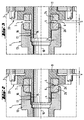
In Figur 2 ist eine Ausführungsform der Erfindung dargestellt, die in wesentlichen Teilen mit
der Ausführung nach Figur 1 identisch ist, jedoch auch einige Unterschiede aufweist. Zum
Beispiel wird der zentrale Anschluß 25 am hinteren Ende des Gehäuses in radialer Richtung
herausgeführt, auch wenn letzlich die Zufuhr dieses Mediums in axialer Richtung und zentral
verläuft. Der Hauptunterschied liegt jedoch gegenüber der Ausführungsform nach Figur 1
darin, daß die Hohlwelle 13' in dem Gehäuse 3' kugelgelagert gehalten wird. Dadurch ist eine
noch bessere Führung der Hohlwelle möglich, vor allen Dingen erfolgt diese Führung sehr nahe
an den zylindrischen Dichtflächen 14, 16 und die Lager 22, 23 sind in dasselbe Gehäuse
integriert, in welchem auch die Dichtfläche 16 fixiert ist. Dadurch lassen sich die Zylindermantelflächen
14, 16 mit noch engerer Toleranz herstellen und man erreicht dementsprechend
noch geringere Leckverluste für das nicht-schmierende Medium.In Figure 2 an embodiment of the invention is shown, the essential parts with
1 is identical, but also has some differences. To the
Example, the
Mit 15 ist ein Innensechskant innerhalb der Bohrung der Hohlwelle 13' bezeichnet, der die
Drehfeste Mitnahme einer in der Hohlwelle aufgenommenen und axial verschiebbaren
Spannstange bewirkt. Nicht oder nur ansatzweise dargestellt ist in den Figuren eine mehr oder
weniger elastische Lagerung einer der Dichtflächen in radialer Richtung, wodurch ein gewisser
Ausgleich von Toleranzabweichung der Rundheit der Flächen 14, 16 erzielt werden kann.With 15 an internal hexagon is designated within the bore of the hollow shaft 13 ', which
Non-rotatable entrainment of an axially displaceable accommodated in the hollow shaft
Tension rod causes. Not shown or only partially shown in the figures one more or
less elastic storage of one of the sealing surfaces in the radial direction, which makes a certain
Compensation of tolerance deviation of the roundness of the
Claims (12)
Applications Claiming Priority (2)
| Application Number | Priority Date | Filing Date | Title |
|---|---|---|---|
| DE19932355A DE19932355B4 (en) | 1999-07-10 | 1999-07-10 | Rotary feedthrough for changing media |
| DE19932355 | 1999-07-10 |
Publications (3)
| Publication Number | Publication Date |
|---|---|
| EP1069362A2 true EP1069362A2 (en) | 2001-01-17 |
| EP1069362A3 EP1069362A3 (en) | 2003-10-01 |
| EP1069362B1 EP1069362B1 (en) | 2006-02-08 |
Family
ID=7914384
Family Applications (1)
| Application Number | Title | Priority Date | Filing Date |
|---|---|---|---|
| EP00113749A Expired - Lifetime EP1069362B1 (en) | 1999-07-10 | 2000-06-29 | Rotatable connection for alternate mediums |
Country Status (7)
| Country | Link |
|---|---|
| US (1) | US6406065B1 (en) |
| EP (1) | EP1069362B1 (en) |
| JP (1) | JP4632489B2 (en) |
| KR (1) | KR100769376B1 (en) |
| CZ (1) | CZ296638B6 (en) |
| DE (2) | DE19932355B4 (en) |
| TW (1) | TW464742B (en) |
Cited By (4)
| Publication number | Priority date | Publication date | Assignee | Title |
|---|---|---|---|---|
| EP2813740A3 (en) * | 2013-06-11 | 2015-03-25 | Christian Maier GmbH & Co. KG Maschinenfabrik | Device for transporting media |
| CN109127920A (en) * | 2018-11-09 | 2019-01-04 | 重庆交通大学 | Gas film lubrication guiding device and mold |
| US11141577B2 (en) * | 2018-09-25 | 2021-10-12 | Megadyne Medical Products, Inc. | Fluid system connector |
| WO2023138727A1 (en) * | 2022-01-18 | 2023-07-27 | Smets-Technology Gmbh | Rotary feedthrough for a gearbox |
Families Citing this family (29)
| Publication number | Priority date | Publication date | Assignee | Title |
|---|---|---|---|---|
| DE10135533B4 (en) * | 2001-07-20 | 2007-04-12 | Mosmatic Ag | Hinge for high-pressure devices for connecting a non-rotating part to a rotating part |
| US6598502B1 (en) * | 2002-01-28 | 2003-07-29 | Titan Technologies International, Inc. | Multi-swivel connector for a fluid operated tool |
| NO316470B1 (en) * | 2002-05-08 | 2009-11-16 | Advanced Prod & Loading As | Device for connecting pipelines carrying fluid under pressure |
| DE10225272B4 (en) | 2002-06-07 | 2005-05-04 | Ott-Jakob Gmbh & Co Spanntechnik Kg | Rotary union |
| US7229102B2 (en) * | 2002-12-20 | 2007-06-12 | Deublin Company | Fluid coolant union |
| DE20305185U1 (en) | 2003-03-31 | 2003-05-28 | Deckel Maho Pfronten GmbH, 87459 Pfronten | Spindle unit for machining device, comprising pneumatically separated sliding elements |
| US7083200B2 (en) * | 2003-08-28 | 2006-08-01 | Focal Technologies Corporation | Fluid rotary union |
| DE10349968A1 (en) * | 2003-10-24 | 2005-05-25 | GAT Gesellschaft für Antriebstechnik mbH | Radial rotary feedthrough |
| DE102004003459B4 (en) * | 2004-01-22 | 2009-07-02 | GAT Gesellschaft für Antriebstechnik mbH | Gleitringfixierung |
| FR2880669B1 (en) * | 2005-01-07 | 2007-04-06 | Univ Limoges | ROTATING JOINT DEVICE FOR CONDUIT USE IN ANALYTICAL CHEMISTRY |
| JP5335180B2 (en) * | 2005-05-17 | 2013-11-06 | デューブリン カンパニー | Multi-media rotating union |
| DE102005038459A1 (en) * | 2005-08-13 | 2007-02-22 | Ott-Jakob Gmbh & Co. Spanntechnik Kg | Rotary feedthrough with leakage sensor |
| DE102005052067A1 (en) * | 2005-10-28 | 2007-05-03 | Georg Springmann Industrie- Und Bergbautechnik Gmbh | Device for coupling a coolant supply to a roller |
| AU2006326839B2 (en) | 2005-12-21 | 2012-05-24 | Taimi R & D Inc. | Self-lubricating swivelling coupling |
| US8307849B2 (en) * | 2008-06-03 | 2012-11-13 | Jergens, Inc. | Rotary coupler and method of using same |
| JP5221278B2 (en) * | 2008-10-22 | 2013-06-26 | リックス株式会社 | Rotary joint |
| DE102009008425A1 (en) * | 2009-02-11 | 2010-09-16 | Mosmatic Ag | Rotary hinge i.e. angle rotary hinge, for connecting non-rotating part with rotating part of high pressure device, has axial sealing ring arranged in area of contact surface and forms contact surface between bushes by axial front surface |
| US8453675B2 (en) * | 2009-12-01 | 2013-06-04 | Deublin Company | Rotary union with selectively controlled seal |
| WO2012129138A2 (en) * | 2011-03-18 | 2012-09-27 | Cool Clean Technologies, Inc. | Method and apparatus for thermal control within a machining process |
| CA2822554A1 (en) * | 2012-08-03 | 2014-02-03 | Deublin Company | Rotary union with pressure controlled seal actuator |
| JP5998082B2 (en) * | 2013-03-14 | 2016-09-28 | エヌティーツール株式会社 | Rotary joint |
| US9970577B2 (en) | 2013-09-27 | 2018-05-15 | The Procter & Gamble Company | Rotary union |
| JP6169993B2 (en) * | 2014-03-11 | 2017-07-26 | 日本ピラー工業株式会社 | Rotary joint for clean fluid |
| DE102016112470A1 (en) | 2016-07-07 | 2018-01-11 | GAT Gesellschaft für Antriebstechnik mbH | Powder rotary feedthrough with rinsing chamber |
| US11278996B2 (en) | 2018-08-31 | 2022-03-22 | Deublin Company, LLC | Rotary seal |
| US11602815B2 (en) * | 2019-01-31 | 2023-03-14 | Fusion Coolant Systems, Inc. | Machining systems utilizing supercritical fluids |
| CN115218051B (en) * | 2022-08-11 | 2024-02-02 | 温州金业气动科技有限公司 | High-speed rotary joint |
| WO2024214129A1 (en) * | 2023-04-10 | 2024-10-17 | Dmg森精機株式会社 | Table |
| TWI897497B (en) * | 2024-06-27 | 2025-09-11 | 富世達股份有限公司 | Pipe coupling structure for fluid transportation system |
Family Cites Families (29)
| Publication number | Priority date | Publication date | Assignee | Title |
|---|---|---|---|---|
| US2626166A (en) * | 1950-03-21 | 1953-01-20 | Fawick Airflex Company Inc | Plural-passage rotary fluid seal |
| US2727760A (en) * | 1950-10-07 | 1955-12-20 | Fawick Corp | High-speed rotary fluid seal |
| US3694008A (en) * | 1970-10-27 | 1972-09-26 | Bowen Tools Inc | Rotating joint |
| US3804424A (en) | 1972-04-24 | 1974-04-16 | Crane Packing Co | Gap seal with thermal and pressure distortion compensation |
| US3889983A (en) * | 1974-04-15 | 1975-06-17 | Duff Norton Co | Rotary fluid joint |
| JPS605168Y2 (en) * | 1979-05-14 | 1985-02-16 | 日新製鋼株式会社 | oil mist seal |
| JPS6017306Y2 (en) * | 1980-04-03 | 1985-05-28 | 東芝機械株式会社 | Rotary joint for molten resin passage pipe |
| AT378037B (en) * | 1982-09-09 | 1985-06-10 | Voest Alpine Ag | DEVICE FOR SUPPLYING A PRESSURIZED LIQUID TO A ROTATING MACHINE PART |
| US4669760A (en) * | 1986-02-05 | 1987-06-02 | Flow Industries, Inc. | Swivel fitting arrangement for use in a pressurized fluid line |
| US4848400A (en) * | 1988-02-19 | 1989-07-18 | Fsi International, Inc. | Rotary fluid coupling |
| DE3817799C1 (en) * | 1988-05-26 | 1989-11-30 | A. Ott Gmbh, 8960 Kempten, De | Rotary transmission leadthrough for fluids, in particular for machine-tool spindles |
| US4976282A (en) * | 1989-04-12 | 1990-12-11 | Deublin Company | Coolant union with fluid actuated seal assembly |
| JP2871082B2 (en) * | 1990-11-29 | 1999-03-17 | ブラザー工業株式会社 | Fluid supply fitting |
| DE4103376C1 (en) * | 1991-02-05 | 1992-08-06 | Ott Maschinentechnik Gmbh, 8960 Kempten, De | |
| JPH051792A (en) * | 1991-06-20 | 1993-01-08 | Honda Motor Co Ltd | Rotary joint |
| US5226677A (en) * | 1991-08-09 | 1993-07-13 | The Johnson Corporation | Rotary joint with extended life seal |
| DE4210009C2 (en) * | 1992-03-27 | 1994-05-11 | Heidelberger Druckmasch Ag | Rotary union |
| JPH05296376A (en) * | 1992-04-20 | 1993-11-09 | Brother Ind Ltd | Rotary coupling for feeding fluid |
| JP2906007B2 (en) * | 1993-02-12 | 1999-06-14 | 株式会社牧野フライス製作所 | Rotary joint |
| JPH0826152A (en) | 1994-07-19 | 1996-01-30 | Mitsubishi Agricult Mach Co Ltd | Temporary setting mechanism of crawler guide for farm working vehicle |
| JPH0826151A (en) | 1994-07-19 | 1996-01-30 | Mitsubishi Heavy Ind Ltd | Driver's seat of body bending type dump truck |
| US5538292A (en) * | 1995-01-17 | 1996-07-23 | Midwest Brake Bond Company | Rotary union |
| US5669636A (en) * | 1995-08-01 | 1997-09-23 | Deublin Company | Floating seal assembly for a bearingless coolant union having air rotation capability |
| US5651567A (en) * | 1995-12-27 | 1997-07-29 | Kaleniecki; James F. | Multi-passage bearingless fluid coupler |
| JP3801677B2 (en) * | 1996-01-19 | 2006-07-26 | リックス株式会社 | Rotary joint |
| JP3801676B2 (en) * | 1996-01-19 | 2006-07-26 | リックス株式会社 | Rotary joint |
| US6109659C1 (en) * | 1998-06-12 | 2002-02-26 | Power Transmission Tech | Hydrostatic rotary union |
| US6203072B1 (en) * | 1999-08-30 | 2001-03-20 | The Johnson Corporation | Corrugating joint and syphon system |
| US6164316A (en) * | 1999-12-23 | 2000-12-26 | Deublin Company | High temperature rotating union |
-
1999
- 1999-07-10 DE DE19932355A patent/DE19932355B4/en not_active Expired - Fee Related
-
2000
- 2000-06-29 DE DE50012182T patent/DE50012182D1/en not_active Expired - Lifetime
- 2000-06-29 EP EP00113749A patent/EP1069362B1/en not_active Expired - Lifetime
- 2000-07-04 CZ CZ20002534A patent/CZ296638B6/en not_active IP Right Cessation
- 2000-07-05 KR KR1020000038312A patent/KR100769376B1/en not_active Expired - Fee Related
- 2000-07-07 TW TW089113481A patent/TW464742B/en not_active IP Right Cessation
- 2000-07-07 US US09/612,037 patent/US6406065B1/en not_active Expired - Fee Related
- 2000-07-10 JP JP2000207979A patent/JP4632489B2/en not_active Expired - Fee Related
Cited By (4)
| Publication number | Priority date | Publication date | Assignee | Title |
|---|---|---|---|---|
| EP2813740A3 (en) * | 2013-06-11 | 2015-03-25 | Christian Maier GmbH & Co. KG Maschinenfabrik | Device for transporting media |
| US11141577B2 (en) * | 2018-09-25 | 2021-10-12 | Megadyne Medical Products, Inc. | Fluid system connector |
| CN109127920A (en) * | 2018-11-09 | 2019-01-04 | 重庆交通大学 | Gas film lubrication guiding device and mold |
| WO2023138727A1 (en) * | 2022-01-18 | 2023-07-27 | Smets-Technology Gmbh | Rotary feedthrough for a gearbox |
Also Published As
| Publication number | Publication date |
|---|---|
| CZ20002534A3 (en) | 2001-02-14 |
| JP2001050451A (en) | 2001-02-23 |
| US6406065B1 (en) | 2002-06-18 |
| DE50012182D1 (en) | 2006-04-20 |
| CZ296638B6 (en) | 2006-05-17 |
| KR100769376B1 (en) | 2007-10-22 |
| KR20010049718A (en) | 2001-06-15 |
| JP4632489B2 (en) | 2011-02-16 |
| EP1069362A3 (en) | 2003-10-01 |
| DE19932355A1 (en) | 2001-01-25 |
| EP1069362B1 (en) | 2006-02-08 |
| TW464742B (en) | 2001-11-21 |
| DE19932355B4 (en) | 2010-07-15 |
Similar Documents
| Publication | Publication Date | Title |
|---|---|---|
| EP1069362B1 (en) | Rotatable connection for alternate mediums | |
| DE69411227T2 (en) | Maze gas seal | |
| DE3877762T2 (en) | MECHANICAL SEAL WITH CENTERING AGENTS. | |
| DE3876985T2 (en) | SCREW ROTOR MACHINE. | |
| DE19525343C2 (en) | Device for transferring fluid between machine parts rotatable relative to one another | |
| DE3840487C2 (en) | Shaft seal arrangement | |
| EP2063156B1 (en) | Double seal arrangement | |
| DE102011050662B4 (en) | rolling tool | |
| DE3537740A1 (en) | STORAGE SYSTEM | |
| DE69310494T2 (en) | High speed slewing ring | |
| EP1526316B1 (en) | Radial rotary connection | |
| DE1944942A1 (en) | Screw compressor and method for its use | |
| EP0955123B1 (en) | Device for fluid conveyance | |
| DE60300051T2 (en) | shaft seal | |
| EP0274090A2 (en) | Seal | |
| DE102004031350B4 (en) | Two-way rotary union | |
| DE2710236C3 (en) | Screw pump | |
| DE2403173B2 (en) | Double mechanical seal | |
| EP2281135A1 (en) | High-performance rotary feedthrough | |
| DE4019987C2 (en) | Rotary union | |
| DE10017669A1 (en) | Gas-lubricated slide ring seal has buffer fluid feed arrangement connected to feed bore in ring seal with feed opening connected to sealing surfaces in fluid supply channel concentric to shaft | |
| DE102010005537A1 (en) | Axially twistable anti-friction bearing for use as groove ball bearing, angular ball bearing or roller bearing for machine tool, has outer ring and inner ring, where outer ring and inner ring have carrier brackets | |
| EP1059475B1 (en) | Mechanical seal arrangement | |
| DE102023211787B4 (en) | Electromechanical actuator with sliding piston for improved hydrodynamic bearing | |
| DE3008491A1 (en) | Double-acting slip-ring seal - has elastic seal thrust axially against slip-ring stop by pressure difference |
Legal Events
| Date | Code | Title | Description |
|---|---|---|---|
| PUAI | Public reference made under article 153(3) epc to a published international application that has entered the european phase |
Free format text: ORIGINAL CODE: 0009012 |
|
| AK | Designated contracting states |
Kind code of ref document: A2 Designated state(s): AT BE CH CY DE DK ES FI FR GB GR IE IT LI LU MC NL PT SE |
|
| AX | Request for extension of the european patent |
Free format text: AL;LT;LV;MK;RO;SI |
|
| PUAL | Search report despatched |
Free format text: ORIGINAL CODE: 0009013 |
|
| AK | Designated contracting states |
Kind code of ref document: A3 Designated state(s): AT BE CH CY DE DK ES FI FR GB GR IE IT LI LU MC NL PT SE |
|
| AX | Request for extension of the european patent |
Extension state: AL LT LV MK RO SI |
|
| 17P | Request for examination filed |
Effective date: 20031216 |
|
| AKX | Designation fees paid |
Designated state(s): CH DE FR GB IT LI |
|
| GRAP | Despatch of communication of intention to grant a patent |
Free format text: ORIGINAL CODE: EPIDOSNIGR1 |
|
| GRAS | Grant fee paid |
Free format text: ORIGINAL CODE: EPIDOSNIGR3 |
|
| GRAA | (expected) grant |
Free format text: ORIGINAL CODE: 0009210 |
|
| AK | Designated contracting states |
Kind code of ref document: B1 Designated state(s): CH DE FR GB IT LI |
|
| REG | Reference to a national code |
Ref country code: GB Ref legal event code: FG4D Free format text: NOT ENGLISH |
|
| REG | Reference to a national code |
Ref country code: CH Ref legal event code: NV Representative=s name: AMMANN PATENTANWAELTE AG BERN Ref country code: CH Ref legal event code: EP |
|
| GBT | Gb: translation of ep patent filed (gb section 77(6)(a)/1977) |
Effective date: 20060208 |
|
| REF | Corresponds to: |
Ref document number: 50012182 Country of ref document: DE Date of ref document: 20060420 Kind code of ref document: P |
|
| PGFP | Annual fee paid to national office [announced via postgrant information from national office to epo] |
Ref country code: IT Payment date: 20060630 Year of fee payment: 7 |
|
| ET | Fr: translation filed | ||
| PLBE | No opposition filed within time limit |
Free format text: ORIGINAL CODE: 0009261 |
|
| STAA | Information on the status of an ep patent application or granted ep patent |
Free format text: STATUS: NO OPPOSITION FILED WITHIN TIME LIMIT |
|
| 26N | No opposition filed |
Effective date: 20061109 |
|
| PG25 | Lapsed in a contracting state [announced via postgrant information from national office to epo] |
Ref country code: IT Free format text: LAPSE BECAUSE OF NON-PAYMENT OF DUE FEES Effective date: 20070629 |
|
| REG | Reference to a national code |
Ref country code: FR Ref legal event code: ST Effective date: 20100226 |
|
| PG25 | Lapsed in a contracting state [announced via postgrant information from national office to epo] |
Ref country code: FR Free format text: LAPSE BECAUSE OF NON-PAYMENT OF DUE FEES Effective date: 20090630 |
|
| PGFP | Annual fee paid to national office [announced via postgrant information from national office to epo] |
Ref country code: FR Payment date: 20080424 Year of fee payment: 9 |
|
| PGFP | Annual fee paid to national office [announced via postgrant information from national office to epo] |
Ref country code: CH Payment date: 20120622 Year of fee payment: 13 |
|
| PGFP | Annual fee paid to national office [announced via postgrant information from national office to epo] |
Ref country code: GB Payment date: 20120622 Year of fee payment: 13 |
|
| PGFP | Annual fee paid to national office [announced via postgrant information from national office to epo] |
Ref country code: DE Payment date: 20130816 Year of fee payment: 14 |
|
| REG | Reference to a national code |
Ref country code: CH Ref legal event code: PL |
|
| GBPC | Gb: european patent ceased through non-payment of renewal fee |
Effective date: 20130629 |
|
| PG25 | Lapsed in a contracting state [announced via postgrant information from national office to epo] |
Ref country code: CH Free format text: LAPSE BECAUSE OF NON-PAYMENT OF DUE FEES Effective date: 20130630 Ref country code: GB Free format text: LAPSE BECAUSE OF NON-PAYMENT OF DUE FEES Effective date: 20130629 Ref country code: LI Free format text: LAPSE BECAUSE OF NON-PAYMENT OF DUE FEES Effective date: 20130630 |
|
| REG | Reference to a national code |
Ref country code: DE Ref legal event code: R119 Ref document number: 50012182 Country of ref document: DE |
|
| REG | Reference to a national code |
Ref country code: DE Ref legal event code: R119 Ref document number: 50012182 Country of ref document: DE Effective date: 20150101 |
|
| PG25 | Lapsed in a contracting state [announced via postgrant information from national office to epo] |
Ref country code: DE Free format text: LAPSE BECAUSE OF NON-PAYMENT OF DUE FEES Effective date: 20150101 |