EP1056239A2 - Einrichtung und Verfahren zur Umschaltung zwischen redundanten Übertragungsgeräte - Google Patents
Einrichtung und Verfahren zur Umschaltung zwischen redundanten Übertragungsgeräte Download PDFInfo
- Publication number
- EP1056239A2 EP1056239A2 EP00110831A EP00110831A EP1056239A2 EP 1056239 A2 EP1056239 A2 EP 1056239A2 EP 00110831 A EP00110831 A EP 00110831A EP 00110831 A EP00110831 A EP 00110831A EP 1056239 A2 EP1056239 A2 EP 1056239A2
- Authority
- EP
- European Patent Office
- Prior art keywords
- switching
- control means
- control
- operational system
- signal
- Prior art date
- Legal status (The legal status is an assumption and is not a legal conclusion. Google has not performed a legal analysis and makes no representation as to the accuracy of the status listed.)
- Withdrawn
Links
Images


Classifications
-
- H—ELECTRICITY
- H04—ELECTRIC COMMUNICATION TECHNIQUE
- H04L—TRANSMISSION OF DIGITAL INFORMATION, e.g. TELEGRAPHIC COMMUNICATION
- H04L1/00—Arrangements for detecting or preventing errors in the information received
- H04L1/22—Arrangements for detecting or preventing errors in the information received using redundant apparatus to increase reliability
Definitions
- the present invention relates to a redundant switching control apparatus with two control sections, operational and standby, of a same configuration, and in particular, to an apparatus and method for redundant switching control ideally suited to telecommunication station equipment, etc. where it is essential to provide stable services by continuing operation even in the event of a fault.
- a redundant configuration is adopted to functional sections critical to continuous operation of the system by having a standby system take over internal information and operating the standby system as a new operational system in the event of a fault or when replacing or before switching the corresponding operational system apparatus so that the system continues to operate without interruption.
- the description above refers to reliable switching control, even in the case where the switching section fails or the switching section is not incorporated, by providing control signal lines between both control sections to implement switching in the event of a fault in the operational system control section.
- the conventional apparatus has various problems such as the necessity of providing a functional section (switching section) to perform control over the status of the redundant control sections and control over a switching command from an upstream monitoring apparatus, which will complicate the configuration and control of the apparatus as a whole and originate an additional need to consider influences of the fault in the switching section itself on the entire apparatus.
- switching section switching section
- the system described in the Publication above also has a problem of rather increasing the complexity in the overall configuration of the apparatus because normal switching control is implemented using a conventional switching section.
- a main subject of the present invention is to connect two control sections in an operating/standby redundant system, one functioning as the operational system to control the controlled section via signal lines that carry signals indicating the status of one control section to the other control section and have both control sections recognize the status of each other from the signals above via these signal lines allowing switching over to either the operational system or standby system.
- FIG.1 is a block diagram showing a configuration of a redundant switching control apparatus according to an embodiment of the present invention.
- Redundant switching control apparatus 100 shown in FIG.1 is intended for use, for example, in a section performing call control of a base station apparatus in a mobile communication system where it is imperative to continue operation even if a fault occurs and comprises first and second control sections 101 and 102, common memory section 103, first and second switches 104 and 105.
- First and second control sections 101 and 102 have an identical configuration - one operating as an operational system and the other operating as a standby system - and the operational system is designed to have control (for example, communication control) over controlled section 106 such as a communication apparatus, both of which are connected via signal lines 107 and 108 connecting between the control sections to allow one to know the status of the other and receive a switching command, etc. from the other.
- control for example, communication control
- controlled section 106 such as a communication apparatus
- first and second control sections 101 and 102 are connected to monitoring apparatus 110 for a supervisor to monitor the equipment via first and second switches 104 and 105 so that these control sections receive a switching command, etc. from monitoring apparatus 110.
- control section for example, 101
- first and second control sections 101 and 102 are provided with timers 111 and 112 and these timers 111 and 112 are used to set a maximum time to determine the startup condition of the control section at startup after a reset, etc.
- Common memory section 103 is shared by first and second control sections 101 and 102 to write/read data, for example, to save information to be transferred at the time of switching between the operational and standby systems.
- First and second switches 104 and 105 are turned ON/OFF under the control of first and second control sections 101 and 102. As shown in FIG.1, for example, if first control section 101 functions as an operational system, switch 104 is turned ON and second switch 105 is turned OFF.
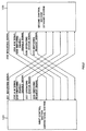
- First control section 101 sends mounting signal 201, ALM (alarm) signal 203, switching enable/disable signal 205, operating status signal 207 and switching request signal 209 to second control section 102 via signal line 107 between the control sections, and second control section 102 sends mounting signal 202, ALM (alarm) signal 204, switching enable/disable signal 206, operating status signal 208 and switching request signal 210 to first control section 101 via signal line 108 between the control sections.
- signals having a common name between first and second control sections indicate a same content, and therefore only one side of them is explained below.
- Mounting signal 201 (or 202) always notifies other control section 102 of the mounting status of own control section 101.
- the status indicated by mounting signal 201 is either "mounted” or "unmounted”.
- ALM signal 203 (or 204) notifies other control section 102 of the status monitored by hardware and software of own control section 101.
- the status indicated by ALM signal 203 is either a normal operating state indicating that own control section 101 is operating normally or an ALM state indicating that an error has occurred.
- This ALM state can have a plurality of states according to the level of the fault.
- Switching enable/disable signal 205 (or 206) is used for operational system control section 101 to enable/disable execution of switching control by standby system control section 102.
- the status indicated by switching enable/disable signal 205 is either a "switching enabled” state or “switching disabled” state of the own control section.
- determination of the operational system or standby system at the time of initial startup or switching back prohibition control is also implemented using this signal.
- switching enable/disable signal 205 indicates a "switching disabled” state, priority is given to control by mounting signal 201 and ALM signal 203.
- there are two types of switching disable time a fixed time of 10 sec or 1 minute and an indefinite time until certain processing ends.
- Operating status signal 207 (or 208) notifies other control section 102 of whether own control section 101 is operating or not.
- the status indicated by operating status signal 207 is "operating” or “non-operating”.
- Switching request signal 209 (or 210) is used to have standby control section 102 start switching control when operational system control section 101 receives a switching command from monitoring apparatus 110. That is, switching request signal 209 carries a switching request that instructs the standby system to start switching control.
- the standby system control section (for example, 102) keeps constant watch on or waits for a chance to interrupt mounting signal 201 and ALM signal 203 of other control section 101, and upon detection of an "unmounted" or abnormal state, the standby system control section immediately executes switching control to become the operational system.
- Information to be transferred to control section 102, which becomes the new operational system after the switching, is stored in common memory section 103 and control section 102, which becomes the new operational system acquires the access right to have access to common memory section 103 by setting operating status signals 207 and 208 to "operating".
- control section 101 This is the method to operate both of redundant control sections 101 and 102 by same hardware and software, however it is also applicable when only one control section (for example, control section 101) is started or other control section 102 is started while only control section 101 is operating.
- both operating/standby system control sections 101 and 102 set switching enable/disable signals 205 and 206 to a switching disabled state.
- the operational system or standby system is determined according to the mounting positions of control sections 101 and 102.
- the mounting positions refer to positions on an apparatus rack on which control sections 101 and 102 are mounted and the operational system or standby system is determined according to these positions.
- first control section 101 when focused on first control section 101, if this first control section 101 is mounted as the operational system at startup, in ST303, first control section 101 sets a maximum time for determining the startup status of the other control section 102 at startup (startup determination) in timer 111.
- first control section 101 determines whether operating status signal 207 of other control section 102 is "operating" or “non-operating” (status other than operating status). If the determination result shows that operating status signal 207 is "operating”, in ST305, first control section 101 sets switching enable/disable signal 205 to a switching enabled status, and then enters into a standby state in ST306.
- first control section 101 determines whether mounting signal 201 of other control section 102 is "unmounted” or not, or whether ALM signal 203 is an ALM state or not. In the case of either an unmounted state or ALM state, in ST309, first control section 101 cancels timer 111, and in ST310, transfers processing to the operational system, and in ST311, sets switching enable/disable signal 205 to "switching enabled” and then in ST312, becomes the operational system.
- the determination result in ST302 shows that first control section 101 is mounted as the standby system at startup, in ST313, switching enable/disable signal 205 is set to "switching enabled", and in ST314, a maximum time for determining the startup status of other control section 102 at startup (startup determination) is set in timer 111.
- first control section 101 determines whether operating status signal 207 of other control section 102 is "operating” or “non-operating” (status other than operating status). If this determination result shows that operating status signal 207 is " operating”, in ST316, first control section 101 enters into a standby state.
- first control section 101 determines whether mounting signal 201 of other control section 102 is in an unmounted state or not, or whether ALM signal 203 is in an ALM state or not. In the case of either an unmounted state or ALM state, in ST318, first control section 101 cancels timer 111, and in ST319 sets switching enable/disable signal 205 to "switching disabled", and in ST320 transfers processing to the operational system, and in ST321 sets switching enable/disable signal 205 to "switching enabled” and then in ST322, becomes the operational system.
- switching control by the maintenance system can be prevented by the control section in the operational system setting switching enable/disable signal 205 to "switching disabled.”
- control section operating as the operational system after switching can implement switching prevention by notifying "switching disabled" to the other control section using switching enable/disable signal 205.
- the redundant switching control apparatus of the present embodiment connects redundant control sections 101 and 102 via signal lines 107 and 108 between the control sections, operates mounting signals 201 and 202, ALM signals 203 and 204, switching enable/disable signals 205 and 206, operating status signals 207 and 208 and switching request signals 209 and 210, and in this way can implement redundant switching control and determination of the operational system at startup without providing any switching section as in the case of the prior art.
- control sections 101 and 102 recognizing their respective operating/standby mounting positions at startup, setting the switching enable/disable signal (e.g., 205) of the system mounted at the operating position to "switching disabled” based on the mounting position information, and setting disable signal 122 of the system mounted at the standby position to "switching enabled", it is possible to specify the operational system in a fixed manner through system determination performed by each of control sections 101 and 102.
- switching enable/disable signal e.g., 205
- upstream monitoring apparatus 110 instructs switching of the system during operation in a redundant configuration, it is possible to implement switching by exercising switching control using switching request signal 209 for switching between control sections 101 and 102 without the need for any external apparatus.
- control section e.g., 101
- the control section that has become the operational system after switching can prevent continuous switching control from monitoring apparatus 110 by keeping switching enable/disable signal 205 in a disabled state for a certain period of time immediately after the switching.
- redundant switching control apparatus 100 using signal lines 107 and 108 between the control sections can perform redundant switching control without providing any switching section as in the case of the prior art, reduce the size of the apparatus and integrate the software structure such as switching processing, system determination processing and switching back prohibition, etc. with signal line monitoring control, thus making it possible to simplify the structure and development of the system, proving extremely effective in practical use.
- the redundant switching control apparatus of the present invention has a redundant configuration of operational and standby systems, comprising two control sections one of which operates as the operational system and controls the controlled section and both are connected via signal lines to carry signals for switching from the operational system to the standby system or from the standby system to the operational system and through these signal lines both sections can recognize the status of each other from the signal above, thereby switching over to either the operational system or standby system.
- the redundant switching control apparatus of the present invention in the above configuration comprises the two control sections further provided with a function of mutually transmitting an alarm signal indicating whether one is in a normal state or abnormal state to the other via signal lines.
- the standby system control section recognizes this abnormal state, and thus can switch over to the operational system.
- the redundant switching control apparatus of the present invention in the above configuration comprises the two control sections further provided with a function of mutually transmitting a mounting signal indicating whether one is in a mounted state or unmounted state to the other via signal lines.
- the own control section recognizes this unmounted state, and thus can switch over to the operational system.
- the redundant switching control apparatus of the present invention in the above configuration comprises the two control sections further provided with a function of mutually transmitting a switching enable/disable signal indicating whether one is in a switching enabled or switching disabled state to the other via signal lines, and if the above two control sections are started simultaneously, the operational system control section sets the switching enable/disable signal of the own section to a switching disabled state and the standby system control section sets the switching enable/disable signal to a switching enabled state.
- the redundant switching control apparatus of the present invention in the above configuration comprises the two control sections further provided with a function of mutually transmitting an operating status signal indicating whether one is operating or not to the other via signal lines.
- the redundant switching control apparatus of the present invention in the above configuration comprises the two control sections further provided with a timer section, and when the two control sections above are started simultaneously, the operational system control section sets an arbitrary timing in the timer section of the own section and determines the state of the other control section from at least one of an operating status signal, switching enable/disable signal, mounting signal and alarm signal to switch between the operational and standby systems within this set time and switches over to either the operational system or standby system according to this determination result.
- the control section mounted in the mounting position of the operational system recognizes the status of the other control section and is switched over to the operational system or standby system only during a set time, allowing quick and appropriate switching between the operational and standby systems without misoperation when a restart, etc. is executed.
- the redundant switching control apparatus of the present invention has, when the two control sections in the above configuration are started simultaneously, such a configuration that the standby system control section sets an arbitrary timing in the timer section of the own section and determines the state of the other control section from an operating status signal, mounting signal and alarm signal to mutually switch between the operational and standby systems within this set time and switches over to either the operational system or standby system according to this determination result.
- the control section mounted in the mounting position of the standby system recognizes the status of the other control section and is switched over to the operational system or standby system only during a set time, allowing quick and appropriate switching between the operational and standby systems without misoperation when a restart, etc. is executed.
- the redundant switching control apparatus of the present invention in the above configuration has such a configuration that a monitoring apparatus that monitors this operating status is connected to the two control sections via a switching section that performs ON/OFF operation, and if either control section becomes the operational system, the control section of the operational system turns ON the above switch section, and turns OFF if that control section becomes the standby system.
- This configuration allows the control section designated as the operational system to be securely connected to the monitoring apparatus.
- the redundant switching control apparatus of the present invention in the above configuration has such a configuration of the two control sections that the operational system control section sends to the standby system control section above, upon reception of a switching command from the monitoring apparatus, the switching request signal instructing that the standby system control section should be switched over to the operational system.
- This configuration allows switching without the need for any external apparatus.
- the redundant switching control apparatus of the present invention in the above configuration has such a configuration that the control section that has become the operational system after the switching sets a switching enable/disable signal to a switching disabled state immediately after the switching.
- This configuration can prevent continuous switching control from the monitoring apparatus and prevent switching immediately after switching (switching back).
- the redundant switching control method of the present invention has a redundant configuration of an operational system and a standby system comprising two control sections, one operating as the operational system controlling the controlled section, with these two control sections connected via signal lines that transmit signals indicating one of a normal/abnormal state, mounted/unmounted state, switching enabled/switching disable state or operating/non-operating state of the own control section to the other control section and performs switching between the operational and standby systems by having one of these two control sections recognize the state of the other based on the signal above via these signal lines.
- This configuration can implement redundant switching control and determination of the operational system at startup without providing any switching section as in the case of the prior art, which avoids complexity in the configuration and control of the entire apparatus and eliminates the need to consider influences of a fault in the switching section itself on the entire apparatus.
- the redundant switching control method of the present invention connects the two control sections to a monitoring apparatus via a switching section, and if one of these control sections becomes the operational system, this control section turns ON the switching section through ON/OFF control of the control section of the operational system, turns OFF the switching section when the control section above becomes the standby system, and upon reception of a switching command from the monitoring apparatus, the control section of the operational system above sends a switching request signal instructing that the standby system control section should be switched over to the operational system to the standby system control section above.
- This method allows the control section that has become the operational system to be securely connected to the monitoring apparatus, making it possible to implement switching without the need for any external apparatus.
- the present invention can configure functions of controlling switching between two control sections in a redundant configuration of operational and standby systems, specification of the initial operational system when the two systems are started simultaneously and prohibition of switching back, without complexity.
Landscapes
- Engineering & Computer Science (AREA)
- Computer Networks & Wireless Communication (AREA)
- Signal Processing (AREA)
- Data Exchanges In Wide-Area Networks (AREA)
- Maintenance And Management Of Digital Transmission (AREA)
- Hardware Redundancy (AREA)
- Safety Devices In Control Systems (AREA)
- Detection And Prevention Of Errors In Transmission (AREA)
- Burglar Alarm Systems (AREA)
Applications Claiming Priority (2)
| Application Number | Priority Date | Filing Date | Title |
|---|---|---|---|
| JP14329899A JP2000330815A (ja) | 1999-05-24 | 1999-05-24 | 二重化切替制御装置及び方法 |
| JP14329899 | 1999-05-24 |
Publications (1)
| Publication Number | Publication Date |
|---|---|
| EP1056239A2 true EP1056239A2 (de) | 2000-11-29 |
Family
ID=15335505
Family Applications (1)
| Application Number | Title | Priority Date | Filing Date |
|---|---|---|---|
| EP00110831A Withdrawn EP1056239A2 (de) | 1999-05-24 | 2000-05-22 | Einrichtung und Verfahren zur Umschaltung zwischen redundanten Übertragungsgeräte |
Country Status (4)
| Country | Link |
|---|---|
| EP (1) | EP1056239A2 (de) |
| JP (1) | JP2000330815A (de) |
| CN (1) | CN1275000A (de) |
| CA (1) | CA2307544A1 (de) |
Cited By (4)
| Publication number | Priority date | Publication date | Assignee | Title |
|---|---|---|---|---|
| CN100377083C (zh) * | 2004-12-20 | 2008-03-26 | 日本电气株式会社 | 启动控制方法、双平台系统以及信息处理器 |
| EP2432152A4 (de) * | 2009-05-25 | 2014-08-06 | Zte Corp | Verfahren und vorrichtung zur umschaltung einer haupt-/standby-einzelplatine |
| CN106648995A (zh) * | 2016-11-29 | 2017-05-10 | 浙江大华技术股份有限公司 | 一种热备份系统中的主机、热备份系统及方法 |
| EP4148507A4 (de) * | 2020-05-19 | 2023-06-21 | Huawei Technologies Co., Ltd. | Steuerungsverfahren und -vorrichtung |
Families Citing this family (31)
| Publication number | Priority date | Publication date | Assignee | Title |
|---|---|---|---|---|
| CN100336309C (zh) * | 2002-05-02 | 2007-09-05 | 中兴通讯股份有限公司 | 一种在主备模块上进行协议呼叫数据处理的方法 |
| KR100533017B1 (ko) * | 2002-07-26 | 2005-12-02 | 엘지전자 주식회사 | 네트워크 라우터의 이중화장치 |
| CN1599292B (zh) * | 2003-09-19 | 2010-04-28 | 中兴通讯股份有限公司 | 一种带线路保护的单板备份方法及装置 |
| CN100452673C (zh) * | 2004-02-16 | 2009-01-14 | 上海欣国信息技术有限公司 | 数字话务台 |
| CN100353710C (zh) * | 2004-06-16 | 2007-12-05 | 华为技术有限公司 | 可升级通信系统及通信系统的升级方法 |
| CN100362482C (zh) * | 2005-07-21 | 2008-01-16 | 上海华为技术有限公司 | 一种双机备份实现方法及系统 |
| JP4776374B2 (ja) * | 2005-12-27 | 2011-09-21 | 株式会社東芝 | 二重化監視制御システム、及び同システムの冗長化切替え方法 |
| JP4625473B2 (ja) * | 2007-01-15 | 2011-02-02 | 株式会社日立製作所 | 冗長切り替え方法 |
| JP2008236311A (ja) * | 2007-03-20 | 2008-10-02 | Fujitsu Ltd | 伝送装置 |
| CN101430550B (zh) * | 2007-03-30 | 2010-12-01 | 哈尔滨工程大学 | 发动机冗余电控系统切换控制方法 |
| CN100492223C (zh) * | 2007-03-30 | 2009-05-27 | 哈尔滨工程大学 | 发动机冗余电控系统切换电路 |
| CN101119187B (zh) * | 2007-09-06 | 2010-05-19 | 上海可鲁系统软件有限公司 | 一种主从设备切换控制方法 |
| JP5054654B2 (ja) * | 2008-10-24 | 2012-10-24 | 三菱電機株式会社 | プラント運転装置 |
| CN101741532B (zh) * | 2008-11-07 | 2012-09-26 | 北京广利核系统工程有限公司 | 一种用于冗余服务器切换的双机切换装置 |
| CN102271047B (zh) * | 2010-06-02 | 2013-09-25 | 杭州华三通信技术有限公司 | 主备倒换方法及主控板、线卡板 |
| JP5503508B2 (ja) * | 2010-11-22 | 2014-05-28 | 株式会社日立製作所 | プラント制御システム、イコライズデータ選択装置、および、イコライズデータ選択方法 |
| JP5583046B2 (ja) * | 2011-02-10 | 2014-09-03 | 株式会社東芝 | 二重化制御装置 |
| JP5450545B2 (ja) * | 2011-09-15 | 2014-03-26 | 株式会社東芝 | サーバ装置 |
| WO2013061494A1 (ja) * | 2011-10-28 | 2013-05-02 | 日本電気株式会社 | 通信中継装置、稼働状態決定方法、通信中継制御基板及び制御プログラムが格納された記憶媒体 |
| WO2014071574A1 (en) * | 2012-11-07 | 2014-05-15 | Abb Technology Ltd | Module, system and method of switching modules |
| CN103618323B (zh) * | 2013-12-05 | 2015-12-02 | 国家电网公司 | 一种基于冗余控制器的statcom控制系统 |
| CN104808482B (zh) * | 2015-03-06 | 2017-03-08 | 南车株洲电力机车有限公司 | 一种故障冗余处理的方法及系统 |
| CN105550076B (zh) * | 2015-12-03 | 2020-02-07 | 北京小鸟科技股份有限公司 | 图像拼接控制系统及其冗余热备份方法 |
| JP2017139696A (ja) * | 2016-02-05 | 2017-08-10 | 沖電気工業株式会社 | 航空管制システム、通信制御装置および通信制御方法 |
| CN107188098B (zh) * | 2017-07-12 | 2023-03-24 | 江苏徐工国重实验室科技有限公司 | 高空作业车控制装置、方法及高空作业车 |
| WO2019207765A1 (ja) * | 2018-04-27 | 2019-10-31 | 三菱電機ビルテクノサービス株式会社 | 無線遠隔監視システム |
| CN112572147A (zh) * | 2019-09-27 | 2021-03-30 | 中车株洲电力机车研究所有限公司 | 一种人机交互系统 |
| CN111781816B (zh) * | 2020-08-05 | 2024-03-19 | 中车大连电力牵引研发中心有限公司 | 一种基于双总线的列车主控设备高速冗余切换方法及系统 |
| CN114194121B (zh) * | 2020-09-02 | 2023-05-12 | 宇通客车股份有限公司 | 一种辅助驾驶系统和车辆 |
| CN113485089B (zh) * | 2021-07-05 | 2024-07-26 | 浙江胄天科技股份有限公司 | 用于移动式海上环境监测设备中的监控系统的控制方法 |
| CN120090261A (zh) * | 2024-12-26 | 2025-06-03 | 国家电网有限公司直流技术中心 | 一种直流换流站控制主机切换方法、设备、介质及产品 |
-
1999
- 1999-05-24 JP JP14329899A patent/JP2000330815A/ja active Pending
-
2000
- 2000-05-04 CA CA002307544A patent/CA2307544A1/en not_active Abandoned
- 2000-05-22 EP EP00110831A patent/EP1056239A2/de not_active Withdrawn
- 2000-05-24 CN CN00117616.1A patent/CN1275000A/zh active Pending
Cited By (5)
| Publication number | Priority date | Publication date | Assignee | Title |
|---|---|---|---|---|
| CN100377083C (zh) * | 2004-12-20 | 2008-03-26 | 日本电气株式会社 | 启动控制方法、双平台系统以及信息处理器 |
| EP2432152A4 (de) * | 2009-05-25 | 2014-08-06 | Zte Corp | Verfahren und vorrichtung zur umschaltung einer haupt-/standby-einzelplatine |
| CN106648995A (zh) * | 2016-11-29 | 2017-05-10 | 浙江大华技术股份有限公司 | 一种热备份系统中的主机、热备份系统及方法 |
| CN106648995B (zh) * | 2016-11-29 | 2019-11-19 | 浙江大华技术股份有限公司 | 一种热备份系统中的第一主机、热备份系统及方法 |
| EP4148507A4 (de) * | 2020-05-19 | 2023-06-21 | Huawei Technologies Co., Ltd. | Steuerungsverfahren und -vorrichtung |
Also Published As
| Publication number | Publication date |
|---|---|
| CA2307544A1 (en) | 2000-11-24 |
| CN1275000A (zh) | 2000-11-29 |
| JP2000330815A (ja) | 2000-11-30 |
Similar Documents
| Publication | Publication Date | Title |
|---|---|---|
| CA2307544A1 (en) | Apparatus and method for redundant switching control | |
| JP2726315B2 (ja) | 移動通信システムの回線異常検出方法 | |
| US5499336A (en) | Monitoring a computer network | |
| US6038681A (en) | Multi-array disk apparatus | |
| US5404389A (en) | Switching system and subscriber's circuit controlling apparatus | |
| JP3844461B2 (ja) | 回線切替接続装置 | |
| JP2520417B2 (ja) | コ−ルウエイテイングサ−ビス方式 | |
| JPH1116605A (ja) | 端末装置 | |
| JPH06197112A (ja) | 管理システム | |
| JP3239856B2 (ja) | ローカルエリアネットワークにおける情報処理装置の障害通知システム及び障害通知装置 | |
| JP2521996B2 (ja) | 通信システムの診断方式 | |
| KR100313756B1 (ko) | 통신 시스템의 기지국 제어카드의 이중화 장치 및 방법 | |
| JP3160927B2 (ja) | ループ試験回路 | |
| JP3069813B2 (ja) | 監視制御方式 | |
| JPH1023048A (ja) | 通信制御方法 | |
| JPH0348997A (ja) | 監視システム | |
| KR100240469B1 (ko) | 알람시스템의 정보전송방법 | |
| KR100324280B1 (ko) | 교환 시스템에서 프로세서의 제어버스 이중화시 오동작 방지방법 | |
| JP2869497B2 (ja) | 複数並列遠隔装置電源投入方式 | |
| KR200182664Y1 (ko) | 교환기의 통화로계에서 클럭 유실 방지 장치 | |
| JP3528825B2 (ja) | 冗長回線切替装置及び冗長回線切替システム | |
| JP2635835B2 (ja) | 呼処理多重監視方式 | |
| JPS6036148B2 (ja) | 障害処理方式 | |
| JP3001424B2 (ja) | 交換機システムの加入者状態監視装置および加入者状態監視方法 | |
| JPS6360940B2 (de) |
Legal Events
| Date | Code | Title | Description |
|---|---|---|---|
| PUAI | Public reference made under article 153(3) epc to a published international application that has entered the european phase |
Free format text: ORIGINAL CODE: 0009012 |
|
| AK | Designated contracting states |
Kind code of ref document: A2 Designated state(s): AT BE CH CY DE DK ES FI FR GB GR IE IT LI LU MC NL PT SE |
|
| AX | Request for extension of the european patent |
Free format text: AL;LT;LV;MK;RO;SI |
|
| STAA | Information on the status of an ep patent application or granted ep patent |
Free format text: STATUS: THE APPLICATION HAS BEEN WITHDRAWN |
|
| 18W | Application withdrawn |
Effective date: 20030128 |