EP1048246B9 - Seat having seat surface of planar elastic body - Google Patents
Seat having seat surface of planar elastic body Download PDFInfo
- Publication number
- EP1048246B9 EP1048246B9 EP98955926A EP98955926A EP1048246B9 EP 1048246 B9 EP1048246 B9 EP 1048246B9 EP 98955926 A EP98955926 A EP 98955926A EP 98955926 A EP98955926 A EP 98955926A EP 1048246 B9 EP1048246 B9 EP 1048246B9
- Authority
- EP
- European Patent Office
- Prior art keywords
- seat
- frame
- resilient material
- sheet resilient
- resin plate
- Prior art date
- Legal status (The legal status is an assumption and is not a legal conclusion. Google has not performed a legal analysis and makes no representation as to the accuracy of the status listed.)
- Expired - Lifetime
Links
Images


Classifications
-
- B—PERFORMING OPERATIONS; TRANSPORTING
- B60—VEHICLES IN GENERAL
- B60N—SEATS SPECIALLY ADAPTED FOR VEHICLES; VEHICLE PASSENGER ACCOMMODATION NOT OTHERWISE PROVIDED FOR
- B60N2/00—Seats specially adapted for vehicles; Arrangement or mounting of seats in vehicles
- B60N2/70—Upholstery springs ; Upholstery
- B60N2/72—Attachment or adjustment thereof
-
- A—HUMAN NECESSITIES
- A47—FURNITURE; DOMESTIC ARTICLES OR APPLIANCES; COFFEE MILLS; SPICE MILLS; SUCTION CLEANERS IN GENERAL
- A47C—CHAIRS; SOFAS; BEDS
- A47C31/00—Details or accessories for chairs, beds, or the like, not provided for in other groups of this subclass, e.g. upholstery fasteners, mattress protectors, stretching devices for mattress nets
- A47C31/02—Upholstery attaching means
- A47C31/023—Upholstery attaching means connecting upholstery to frames, e.g. by hooks, clips, snap fasteners, clamping means or the like
-
- A—HUMAN NECESSITIES
- A47—FURNITURE; DOMESTIC ARTICLES OR APPLIANCES; COFFEE MILLS; SPICE MILLS; SUCTION CLEANERS IN GENERAL
- A47C—CHAIRS; SOFAS; BEDS
- A47C7/00—Parts, details, or accessories of chairs or stools
- A47C7/02—Seat parts
- A47C7/28—Seat parts with tensioned springs, e.g. of flat type
- A47C7/282—Seat parts with tensioned springs, e.g. of flat type with mesh-like supports, e.g. elastomeric membranes
-
- B—PERFORMING OPERATIONS; TRANSPORTING
- B60—VEHICLES IN GENERAL
- B60N—SEATS SPECIALLY ADAPTED FOR VEHICLES; VEHICLE PASSENGER ACCOMMODATION NOT OTHERWISE PROVIDED FOR
- B60N2/00—Seats specially adapted for vehicles; Arrangement or mounting of seats in vehicles
- B60N2/58—Seat coverings
-
- B—PERFORMING OPERATIONS; TRANSPORTING
- B60—VEHICLES IN GENERAL
- B60N—SEATS SPECIALLY ADAPTED FOR VEHICLES; VEHICLE PASSENGER ACCOMMODATION NOT OTHERWISE PROVIDED FOR
- B60N2/00—Seats specially adapted for vehicles; Arrangement or mounting of seats in vehicles
- B60N2/58—Seat coverings
- B60N2/5816—Seat coverings attachments thereof
- B60N2/5825—Seat coverings attachments thereof by hooks, staples, clips, snap fasteners or the like
Definitions
- the present invention relates to an improvement of a seat including a seat frame comprising a substantially quadrilateral frame body, in which a seating face is made of sheet resilient material by stretching a net-like sheet resilient body within the frame of the seat frame.
- a seat forming a seating face by stretching net-like sheet resilient material within a frame of a seat frame has already been proposed (U.S.P. 5,013,089, U.S.P. 5,533,789 and Japanese Patent Application Laid-open No.H8-507935).
- the seating face of the seat is formed of the sheet resilient material, it is possible to change the design of the seat from a normal seat, and not only the cushion properties but also breathability can be applied to the seating face, and furthermore, a pad member, a spring member and the like which constitute the seating face can be omitted, the weight can be lightened, the assembled seat has excellent space efficiency due to the thin thickness of the sheet resilient material.
- a resin plate is mounted to an end of the sheet resilient material and is fitted in a recess formed on an axial of the seat frame, thereby fixing the end of the sheet resilient material, or the end of the sheet resilient material is directly wound around the axis of the seat frame and fixed together with a push plate by screw.
- bank can not be provided almost at all in the seat and thus, holding properties of a sitting passenger is inferior.
- a hard resin plate or the push plate is located around the frame, such hard resin plate or the push plate contacts the sitting passenger and thus he or she may feel a sense of incongruity, which is not preferable.
- a seat having a seating face made of sheet resilient material of the present invention is assembled from a seat frame comprising a substantially quadrilateral frame body, the sheet resilient material forming the seating face, a pad member forming a largely rising bank, and a skin material enclosing the pad member, wherein the sheet resilient material is stretched within the frame body of the seat frame, one end of the skin material is abutted against and fixed on the frame body of the seat frame, the pad member is assembled outside the seat frame, the skin material covers outside of the pad member from the one end which is abutted against and fixed on the frame body of the seat frame, and the other end is wound and stopped around the back of the seat frame.
- the bank which rises larger than the seating surface of the seating face made of the sheet resilient material which is stretched within the frame body of the seat frame is formed and thus, it is possible to enhance the holding properties of the sitting passenger.
- the pad member which is assembled outside the seat frame is covered with the skin material having the one side which is abutted against and fixed to the frame body of the seat frame and the other end wound around and stopped at the back of the seat frame and therefore, the bank which rises larger than the seating surface of the seating face made of the sheet resilient material can be assembled strongly with a simple structure.
- the pad member covers the seat frame including the end of the sheet resilient material stopped at the seat frame and the one end of the skin material which is abutted against and fixed on the frame body of the seat frame and thus, the pad member prevents the seat frame from touching a sitting passenger so that the sitting passenger should not feel a sense of incongruity.
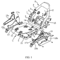
- Figs. 1 to 5 As illustrated modes for carrying out the present invention, there are a first embodiment shown in Figs. 1 to 5, a second embodiment shown in Figs. 6 and 7, and a third embodiment shown in Figs. 8 to 10.
- Each of the embodiments is applied to the assembling of a seat back B and a seat cushion C of a vehicle as shown in Fig. 1.
- Each of the seat back B and the seat cushion C of the vehicle seat is assembled from a substantially quadrilateral frame-like seat frame 1, 10, a sheet resilient material 2, 11, forming a seating face, a pad member 3, 12, forming a largely rising bank, and a skin material 4, 13, covering the pad member 3, 12.
- a metal frame having U-shaped cross section whose inner side is opened is used as the seat back frame 1.
- the seat back frame 1 is bent in the axial direction such that each of sides forming the substantially quadrilateral shape of the seat back frame 1 fits to a contour of a sitting passenger.
- the seat back frame 1 is provided with a plurality of locking pawls 5 ... used for stretching the sheet resilient material 2 within the frame as will be described later.
- the locking pawls 5 ... are so-called “retainers”, and are mounted at a distance from one another by welding on a frame surface closer to an outer peripheral edge on the side on which the sheet resilient material 2 is stretched.
- a cloth having breathability is used as the sheet resilient material 2.
- a cloth formed of a plurality of elastomer monofilaments woven by a plurality of strands such as fiber yarn used for interior cloth, a cloth or a knit to which elasticity and breathability are applied by weaving or knitting 1000 to 4000-denier elastomer monofilament to the warp or the weft can be used as the sheet resilient material 2.
- the sheet resilient material 2 is integrally formed around a periphery of the resilient material 2 with a resin plate 6 made of PET, PP or the like.
- the resin plate 6 inserts the edge of the sheet resilient material 2 into a thick portion so that they are integrally formed by injection forming, thereby stretching the sheet resilient material 2 from its periphery.
- the resin plate 6 is formed at its plate surface with a plurality of slits 6a ... positioned in correspondence with the locking pawls 5 ... of the seat back frame 1, and a plurality of boss-like projections 6b...each having pedestal and rises from the plate surface at a distance from one another.
- the pad member 3 is a cushion foam body such as forming urethane, and is provided with a recess in which a front surface, side surface and a back surface of the seat back frame 1 are fitted and fixed from out side, and is formed into a predetermined cubic shape.
- the pad member 3 may be individually formed for each side of the seat back frame 1, or the entire pad member 3 may be continuously and integrally formed in the frame shape of the seat back frame 1.
- the front side of the pad member 3 largely rises such as to assemble the bank having excellent holding property and especially, a portion thereof from its intermediate portion to the lower portion of both the sides largely rises, and the upper portion largely rises as a head rest portion.
- any material such as a general real leather, a synthetic leather or fabric can be used.
- the entire skin material 4 may be sewn and formed into a continuous integral material such that the skin material can cover the pad member 3 assembled to each side of the seat back frame 1 and having a substantially C-shaped cross section whose inner side is opened.
- a reinforcing cord 7, that is, a so-called “trim cord” is sewn to the skin material 4 along an end wound and stopped at the front surface side of the seat back frame 1.
- the reinforcing cord 7 is provided with a plurality of holes 7a, 7b ... located in correspondence with the projections 6b ... of the supporting plate 6 at a distance from one another in the longitudinal direction.
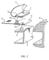
- the locking pawls 5 ... of the seat back frame 1 are inserted into the slits 6a ..., projecting ends of the locking pawls 5 ... are bent outward of the seat back frame 1, the resin plate 6 is abutted against and fixed to the front surface side of the seat back frame 1, thereby stretching the sheet resilient material 2 within the frame body of the seat back frame 1.
- the projections 6b... of the resin plate 6 are fitted into the holes 7a, 7b ... of the reinforcing cord 7, the projecting end side of the projections 6b...
- the reinforcing cord 7 is sandwiched between the pedestals of the projections 6b and the caulked and deformed head portion so that one end of the skin material 4 is stopped and fixed at the front surface side of the seat back frame 1.
- the pad member 3 is assembled to each of the sides of the seat back frame 1 from outside such as to cover the one end of the skin material 4 and the seat back frame 1. Further, the skin material 4 is wound to the back surface side of the seat back frame 1 from the one end which is stopped and fixed to the seat back frame 1 so as to enclose the pad member 3.
- This skin material 4 can be stopped at the end by sewing a hook 8 made of hard resin along the end at the side of winding side, and by hanging the hook 8 on the flange of the seat back frame 1.
- the seating face is made of the sheet resilient material 2 using the seat back frame 1 as a base and the pad member 3 is formed with the largely rising bank, it is possible to hold the sitting passenger stably.
- the peripheral edge of the sheet resilient material 2 is embedded in the thick portion, the resin plate 6 for stretching and holding the sheet resilient material 2 from the periphery is abutted against and fixed to the seat back frame 1 by the locking pawls 5 ... , the one end of the skin material 4 is abutted against and fixed to the seat back frame 1 by the projections 6b ... and thus, it is possible to assemble the seat strongly with a simple structure.
- the pad member 3 assembled to the seat back frame 1 covers the seat back frame 1 of course, and covers the one end of the skin material 4 including the resin plate 6 holding the end of the sheet resilient material 2. Therefore, a sense of incongruity due to the resin plate 6 and the seat back frame 1 should not be applied to the sitting passenger.
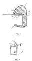
- a square pipe member as shown in Fig. 4 can be used instead of the above described frame having U-shaped cross section.
- the skin material may be formed at its back surface with a back (not shown) which can open and close by a slide fastener or the like.
- the resin plate 6 may be provided at its opposite sides with rising flanges 6c, 6d as shown in Fig. 5. Since the rising flanges 6c, 6d fitted to the opposite sides of the seat frame 1, it is possible to accurately position the resin plate 6 and easily assemble the resin plate 6 to the seat frame 1.
- the resin plate 6 for stretching and holding the sheet resilient material 2 from the periphery is abutted against and fixed to the seat back frame 1 by the locking pawls 5 ...
- the one end of the skin material 4 is abutted against and fixed to the seat back frame 1 by the projections 6b ....
- the skin material 4 can be abutted against and fixed to the seat back frame 1 by engaging the reinforcing cord 7 with the locking pawls 5 ... together with the resin plate 6.
- the resin plate 6 is provided with a plurality of slits 60a, 60b as elongated holes in positions corresponding to the locking pawls 5 ... of the seat back frame 1 in the longitudinal direction.
- the reinforcing cord 7 is provided with a plurality of slits 70a, 70b... in positions corresponding to the slits 60a, 60b ... of the resin plate 6 in the longitudinal direction.
- the reinforcing cord 7 of the skin material 4 is superposed on the resin plate 6 of the sheet resilient material 2, the tip ends of the locking pawls 5... projecting from the slits 60a, 60b of the resin plate 6 are fitted in the aligned slits 70a, 70b of the reinforcing cord 7, the projecting end are bent outward of the seat back frame 1, and the resin plate 6 and the reinforcing cord 7 are fastened fixed together at the side of the front surface of the seat back frame.
- the sheet resilient material 2 can be stretched and held within the frame body of the seat back frame 1 by the resin plate 6 such as to form the seating face. Further, since the seating face is made of the sheet resilient material 2 using the seat back frame 1 as a base and the pad member 3 is enclosed by the skin material 4 which fixes the one end at the front surface side of the seat back frame 1, the bank which rises larger than the surface position of the seating face made of the sheet resilient material 2 can be assembled strongly with a simple structure.
- the metal frame having the U-shaped cross section or the square pipe member is used as the seat back frame 1, and the sheet resilient material 2 is stretched and held from the periphery by the resin plate 6.
- a metal pipe frame 1a is used as a base frame, the pipe frame 1a is embedded in the seat back frame 1, the frame body 1b in which the peripheral edge of the sheet resilient material 2 is incorporated holds the sheet resilient material 2 at a predetermined tensile strength from the periphery.
- the frame body 1b and the pipe frame 1a are integrally formed of resin into the seat back frame 1.
- the frame body 1b can be formed of synthetic resin such as polyethylene terephthalate, polypropylene and polyethylene by the injection forming.
- the frame body 1b is integrally formed of resin with the sheet resilient material 2, as shown in Fig. 9, the sheet resilient material 2 is sandwiched by a fastener P from the periphery, and is stretched and supported with predetermined tensile strength, the peripheral end edge of the sheet resilient material 2 is accommodated in a cavity between an upper die W 1 and a lower die W 2 together with the pipe frame 1a, and is subjected to the injection forming.
- the projections 1c ... for stopping the one end of the skin material 4 and a receiving groove 1d in which a locking plate of the skin material 4 which will be described later are formed by the injection forming on the frame body 1b along the axial direction of the pipe frame 1a.
- the sandwiched portion of the sheet resilient material 2 by the fastener P may be cut and removed as reminder portion by heat cutting along the side edge of the frame body 1 since the sandwiched portion becomes frayed.
- the frame body 1b is integrally formed of resin with the pipe frame la.
- the frame body 1b is formed of resin for taking in the peripheral end edge of the sheet resilient material 2 to stretch and support the sheet resilient material 2 with the predetermined tensile force from periphery. Therefore, it is possible to stretch the sheet resilient material 2 within the frame of the seat back frame 1 while keeping moderate and constant tensile strength evenly.
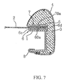
- the reinforcing cord 7 provided with the plurality of holes 7a, 7b ... located in correspondence with the projections 1c ... of the frame body 1b may be sewed on the skin material 4 along the one end which is wound and stopped around the front surface side of the seat back frame 1, and a hanging plate 9 made of resin may be mounted along the other end.
- the resin plate 7 of the skin material 4 is abutted against the front surface side of the frame body 1b, the projections 1c ... are fitted in the holes 7a, 7b ..., the projecting ends of the projections 1c ... are caulked by supersonic wave welding, thermal welding or crush caulking, thereby stopping the one end of the skin material.
- the pad member 3 is incorporated to the seat back frame 1 and enclosed by the skin material 4 such that the pad member 3 comes inside of the skin material 4, and the hanging plate 9 provided at the other end of the skin material 4 is fitted in the receiving groove 1d of the resin frame 1b and fixed.
- the seating face can be formed of the sheet resilient material 2 which is stretched within the frame of the seat back frame 1 while keeping the constant tensile force, and it is possible to assemble, with a simple structure, the strong seat back B having the bank which rises larger than the surface position of the seating face made of the sheet resilient material 2 from the skin material 4 enclosing the pad member 3.
- this seat back is provided with a lumber support 14 whose position can vertically be adjusted by a back cover 15, the back cover 15 is mounted to a lower portion of back surface of the seat back frame 1 so that the seat back can be constituted as a seat back having a back cover and keeping the breathability by the upper portion.
- the seat cushion C is mounted to bracket plates 17a, 17b slidably and uprightly supported by slide rails 16a, 16b, the bracket plates 17a, 17b are covered with exterior covers 18a, 18b, whereby the seat can be constituted in the same manner as a normal seat which can be adjusted in position in the longitudinal direction. Further, if the one bracket plate 17b is provided with a reclining mechanism 19, the seat can be constituted as a reclining seat.
- the seat having the seating face made of the sheet resilient material of the present invention it is possible to form the bank which rises larger than the seating face made of the sheet resilient material which is stretched within the frame body of the seat frame by the pad member which is assembled to the seat frame and covered with the skin material, it is also possible to enhance the holding properties of the passenger, one end of the skin material is abutted against and fixed to the frame body of the seat frame, and the pad member assembled outside the seat frame is covered with the skin material which is wound around a back of the seat frame and fixed at the other end thereof to the back of the seat frame.
- the present invention is suitable for constituting the seat for an automobile.
Landscapes
- Engineering & Computer Science (AREA)
- Aviation & Aerospace Engineering (AREA)
- Transportation (AREA)
- Mechanical Engineering (AREA)
- Seats For Vehicles (AREA)
- Chair Legs, Seat Parts, And Backrests (AREA)
- Mattresses And Other Support Structures For Chairs And Beds (AREA)
Applications Claiming Priority (7)
| Application Number | Priority Date | Filing Date | Title |
|---|---|---|---|
| JP33934097A JP4009706B2 (ja) | 1997-11-25 | 1997-11-25 | 面状弾性体による座面を有するシート |
| JP33934097 | 1997-11-25 | ||
| JP36822297 | 1997-12-26 | ||
| JP36822297A JP4009707B2 (ja) | 1997-12-26 | 1997-12-26 | 面状弾性体による座面部を有するシート |
| JP9091798 | 1998-03-19 | ||
| JP09091798A JP4332868B2 (ja) | 1998-03-19 | 1998-03-19 | 面状弾性体による座面部を有するシート |
| PCT/JP1998/005307 WO1999026519A1 (fr) | 1997-11-25 | 1998-11-25 | Siege possedant une surface fabriquee dans un corps elastique plan |
Publications (4)
| Publication Number | Publication Date |
|---|---|
| EP1048246A1 EP1048246A1 (en) | 2000-11-02 |
| EP1048246A4 EP1048246A4 (en) | 2001-01-17 |
| EP1048246B1 EP1048246B1 (en) | 2004-03-03 |
| EP1048246B9 true EP1048246B9 (en) | 2004-11-03 |
Family
ID=27306570
Family Applications (1)
| Application Number | Title | Priority Date | Filing Date |
|---|---|---|---|
| EP98955926A Expired - Lifetime EP1048246B9 (en) | 1997-11-25 | 1998-11-25 | Seat having seat surface of planar elastic body |
Country Status (6)
| Country | Link |
|---|---|
| US (1) | US6375269B1 (pt) |
| EP (1) | EP1048246B9 (pt) |
| CN (1) | CN1157140C (pt) |
| BR (1) | BR9815422A (pt) |
| DE (2) | DE69822217D1 (pt) |
| WO (1) | WO1999026519A1 (pt) |
Families Citing this family (119)
| Publication number | Priority date | Publication date | Assignee | Title |
|---|---|---|---|---|
| US6758528B2 (en) * | 1999-12-28 | 2004-07-06 | Asahi Gomu Kako Co., Ltd. | Cushion structure manufacturing method and apparatus of the same |
| JP4484346B2 (ja) * | 2000-09-29 | 2010-06-16 | 株式会社デルタツーリング | 車両用シート |
| EP1487663B1 (en) * | 2002-03-22 | 2006-06-07 | Intier Automotive Inc. | Seat frame panel for attaching a fabric suspension |
| FR2841509A1 (fr) * | 2002-06-27 | 2004-01-02 | Cera | Element de garnissage pourvu d'un dispositif de suspension |
| CN100408299C (zh) * | 2002-08-30 | 2008-08-06 | 郑钦明 | 婴幼儿用汽车座椅主体模制方法及其制成的主体 |
| US7055911B2 (en) * | 2003-05-08 | 2006-06-06 | Haworth, Inc. | Mesh chair |
| IL157632A0 (en) * | 2003-08-28 | 2004-03-28 | Keter Plastic Ltd | Furniture item and a method for attaching webbing thereto |
| US20050194829A1 (en) * | 2004-03-08 | 2005-09-08 | Chad Aerts | Fabric attachment device |
| JP4652767B2 (ja) * | 2004-10-13 | 2011-03-16 | 株式会社岡村製作所 | 椅子の背凭れ等における張材の張設構造 |
| WO2006094258A2 (en) * | 2005-03-01 | 2006-09-08 | Haworth, Inc. | Chair back |
| US8465007B2 (en) * | 2006-03-22 | 2013-06-18 | Illinois Tool Works Inc. | Load bearing assembly with elastomeric edge |
| US7913637B2 (en) * | 2007-01-26 | 2011-03-29 | Roehm Marine, Llc | Marine seating system and apparatus |
| US7837263B2 (en) * | 2007-06-14 | 2010-11-23 | Gm Global Technology Operations, Inc. | Vehicle seat construction |
| US20090284057A1 (en) * | 2008-05-14 | 2009-11-19 | Michigan Tube Swagers & Fabricators, Inc. | Stackable chair |
| NZ613957A (en) | 2008-12-12 | 2015-03-27 | Formway Furniture Ltd | A chair, a support, and components |
| JP5515655B2 (ja) * | 2009-02-10 | 2014-06-11 | トヨタ紡織株式会社 | 車両用シートおよび車両用シートの製造方法 |
| JP5434211B2 (ja) * | 2009-04-09 | 2014-03-05 | トヨタ紡織株式会社 | 車両用シートの面状弾性体の組み付け構造 |
| ES2358662B1 (es) * | 2009-10-29 | 2012-03-08 | Centro Tecnológico De Grupo Copo S.L.U. | Sistema de fijación para asientos. |
| EP2534978B1 (en) * | 2010-02-10 | 2016-07-20 | Okamura Corporation | Stretching structure of chair upholstery material |
| WO2011137116A1 (en) * | 2010-04-26 | 2011-11-03 | Haworth, Inc. | Seat assembly for an office chair |
| JP5521801B2 (ja) * | 2010-06-08 | 2014-06-18 | トヨタ紡織株式会社 | 車両用シート |
| JP5561129B2 (ja) * | 2010-11-30 | 2014-07-30 | トヨタ紡織株式会社 | 車両用シート |
| JP2014019415A (ja) * | 2012-07-24 | 2014-02-03 | Toyota Boshoku Corp | 車両用シート |
| US20140054947A1 (en) * | 2012-08-22 | 2014-02-27 | Tung-Hua Su | Backrest assembly with front and rear frames |
| US8998339B2 (en) | 2012-09-20 | 2015-04-07 | Steelcase Inc. | Chair assembly with upholstery covering |
| US11304528B2 (en) | 2012-09-20 | 2022-04-19 | Steelcase Inc. | Chair assembly with upholstery covering |
| USD697726S1 (en) | 2012-09-20 | 2014-01-21 | Steelcase Inc. | Chair |
| US11229294B2 (en) | 2012-09-20 | 2022-01-25 | Steelcase Inc. | Chair assembly with upholstery covering |
| US20150321589A1 (en) * | 2012-11-19 | 2015-11-12 | Ts Tech Co., Ltd. | Seat device |
| JP5976508B2 (ja) * | 2012-11-19 | 2016-08-23 | トヨタ紡織株式会社 | 車両用シート |
| JP5962480B2 (ja) * | 2012-12-12 | 2016-08-03 | トヨタ紡織株式会社 | 線条材の乗物用シートへの取付構造 |
| US9216677B2 (en) | 2013-01-24 | 2015-12-22 | Ford Global Technologies, Llc | Quick-connect trim carrier attachment |
| US9126508B2 (en) | 2013-01-24 | 2015-09-08 | Ford Global Technologies, Llc | Upper seatback pivot system |
| US9902293B2 (en) | 2013-01-24 | 2018-02-27 | Ford Global Technologies, Llc | Independent cushion extension with optimized leg-splay angle |
| US9016784B2 (en) | 2013-01-24 | 2015-04-28 | Ford Global Technologies, Llc | Thin seat leg support system and suspension |
| US9096157B2 (en) | 2013-01-24 | 2015-08-04 | Ford Global Technologies, Llc | Seating assembly with air distribution system |
| US8727374B1 (en) | 2013-01-24 | 2014-05-20 | Ford Global Technologies, Llc | Vehicle seatback with side airbag deployment |
| US9409504B2 (en) | 2013-01-24 | 2016-08-09 | Ford Global Technologies, Llc | Flexible seatback system |
| US9415713B2 (en) | 2013-01-24 | 2016-08-16 | Ford Global Technologies, Llc | Flexible seatback system |
| US9399418B2 (en) | 2013-01-24 | 2016-07-26 | Ford Global Technologies, Llc | Independent cushion extension and thigh support |
| US9061616B2 (en) | 2013-01-24 | 2015-06-23 | Ford Global Technologies, Llc | Articulating headrest assembly |
| US9016783B2 (en) | 2013-01-24 | 2015-04-28 | Ford Global Technologies, Llc | Thin seat flex rest composite cushion extension |
| US9126504B2 (en) | 2013-01-24 | 2015-09-08 | Ford Global Technologies, Llc | Integrated thin flex composite headrest assembly |
| WO2014127355A1 (en) * | 2013-02-18 | 2014-08-21 | Faurecia Automotive Seating, Llc | Seat back for vehicle seat |
| US9193284B2 (en) | 2013-06-11 | 2015-11-24 | Ford Global Technologies, Llc | Articulating cushion bolster for ingress/egress |
| US9527418B2 (en) | 2013-09-12 | 2016-12-27 | Ford Global Technologies, Llc | Semi rigid push/pull vented envelope system |
| US8905431B1 (en) | 2013-09-24 | 2014-12-09 | Ford Global Technologies, Llc | Side airbag assembly for a vehicle seat |
| JP6154907B2 (ja) * | 2013-09-30 | 2017-06-28 | ジョンソン コントロールズ テクノロジー カンパニーJohnson Controls Technology Company | 座席 |
| US9187019B2 (en) | 2013-10-17 | 2015-11-17 | Ford Global Technologies, Llc | Thigh support for customer accommodation seat |
| US9505322B2 (en) | 2013-10-25 | 2016-11-29 | Ford Global Technologies, Llc | Manual lumbar pump assembly |
| US9566884B2 (en) | 2013-11-11 | 2017-02-14 | Ford Global Technologies, Llc | Powered head restraint electrical connector |
| US9315130B2 (en) | 2013-11-11 | 2016-04-19 | Ford Global Technologies, Llc | Articulating head restraint |
| US9365143B2 (en) | 2013-12-12 | 2016-06-14 | Ford Global Technologies, Llc | Rear seat modular cushion |
| US9315131B2 (en) | 2014-01-23 | 2016-04-19 | Ford Global Technologies, Llc | Suspension seat back and cushion system having an inner suspension panel |
| US9649963B2 (en) | 2014-03-04 | 2017-05-16 | Ford Global Technologies, Pllc | Trim and foam assembly for a vehicle seat |
| US9527419B2 (en) | 2014-03-31 | 2016-12-27 | Ford Global Technologies, Llc | Vehicle seating assembly with manual cushion tilt |
| US9421894B2 (en) | 2014-04-02 | 2016-08-23 | Ford Global Technologies, Llc | Vehicle seating assembly with manual independent thigh supports |
| US9302643B2 (en) | 2014-04-02 | 2016-04-05 | Ford Global Technologies, Llc | Vehicle seating assembly with side airbag deployment |
| JP6358612B2 (ja) * | 2014-04-14 | 2018-07-18 | 株式会社タチエス | 車両用シート |
| US9463727B2 (en) * | 2014-08-14 | 2016-10-11 | Honda Motor Co., Ltd. | Vehicle seat covering assembly |
| US9694741B2 (en) | 2014-08-25 | 2017-07-04 | Ford Global Technologies, Llc | Ambient functional lighting of a seat |
| US10471874B2 (en) | 2014-09-02 | 2019-11-12 | Ford Global Technologies, Llc | Massage bladder matrix |
| US9776533B2 (en) | 2014-10-03 | 2017-10-03 | Ford Global Technologies, Llc | Torsion bar upper seatback support assembly |
| US9333882B2 (en) | 2014-10-03 | 2016-05-10 | Ford Global Technologies, Llc | Manual upper seatback support |
| US9789790B2 (en) | 2014-10-03 | 2017-10-17 | Ford Global Technologies, Llc | Tuned flexible support member and flexible suspension features for comfort carriers |
| US9771003B2 (en) | 2014-10-29 | 2017-09-26 | Ford Global Technologies, Llc | Apparatus for customizing a vehicle seat for an occupant |
| US9340131B1 (en) | 2014-11-06 | 2016-05-17 | Ford Global Technologies, Llc | Head restraint with a multi-cell bladder assembly |
| US9517777B2 (en) | 2014-11-06 | 2016-12-13 | Ford Global Technologies, Llc | Lane departure feedback system |
| US10065570B2 (en) | 2014-12-10 | 2018-09-04 | Ford Global Technologies, Llc | Electronic device holder for a vehicle seat |
| US9593642B2 (en) | 2014-12-19 | 2017-03-14 | Ford Global Technologies, Llc | Composite cam carrier |
| US9663000B2 (en) | 2015-01-16 | 2017-05-30 | Ford Global Technologies, Llc | Vehicle seat configured to improve access |
| US9707877B2 (en) | 2015-01-20 | 2017-07-18 | Ford Global Technologies, Llc | Independent thigh extension and support trim carrier |
| US9365142B1 (en) | 2015-01-20 | 2016-06-14 | Ford Global Technologies, Llc | Manual independent thigh extensions |
| US9566930B2 (en) | 2015-03-02 | 2017-02-14 | Ford Global Technologies, Llc | Vehicle seat assembly with side-impact airbag deployment mechanism |
| US9802535B2 (en) | 2015-04-27 | 2017-10-31 | Ford Global Technologies, Llc | Seat having ambient lighting |
| EP3294589B1 (en) * | 2015-05-15 | 2023-10-04 | Adient US LLC | A seat support structure and a seat structure including the seat support structure |
| US10046682B2 (en) | 2015-08-03 | 2018-08-14 | Ford Global Technologies, Llc | Back cushion module for a vehicle seating assembly |
| US9718387B2 (en) | 2015-08-03 | 2017-08-01 | Ford Global Technologies, Llc | Seat cushion module for a vehicle seating assembly |
| US9688174B2 (en) | 2015-08-07 | 2017-06-27 | Ford Global Technologies, Llc | Multi-cell seat cushion assembly |
| US9573528B1 (en) | 2015-08-25 | 2017-02-21 | Ford Global Technologies, Llc | Integrated seatback storage |
| US10463170B2 (en) | 2015-09-09 | 2019-11-05 | Kids Ii, Inc. | Collapsible play yard |
| US9616776B1 (en) | 2015-11-16 | 2017-04-11 | Ford Global Technologies, Llc | Integrated power thigh extender |
| US9809131B2 (en) | 2015-12-04 | 2017-11-07 | Ford Global Technologies, Llc | Anthropomorphic pivotable upper seatback support |
| US9931999B2 (en) | 2015-12-17 | 2018-04-03 | Ford Global Technologies, Llc | Back panel lower clip anchorage features for dynamic events |
| US10093214B2 (en) | 2016-01-14 | 2018-10-09 | Ford Global Technologies, Llc | Mechanical manual leg tilt |
| US9914421B2 (en) | 2016-01-15 | 2018-03-13 | Ford Global Technologies, Llc | Seatback flexible slip plane joint for side air bag deployment |
| US10052990B2 (en) | 2016-01-25 | 2018-08-21 | Ford Global Technologies, Llc | Extended seatback module head restraint attachment |
| US9756408B2 (en) | 2016-01-25 | 2017-09-05 | Ford Global Technologies, Llc | Integrated sound system |
| US10035442B2 (en) | 2016-01-25 | 2018-07-31 | Ford Global Technologies, Llc | Adjustable upper seatback module |
| US9776543B2 (en) | 2016-01-25 | 2017-10-03 | Ford Global Technologies, Llc | Integrated independent thigh supports |
| US10286818B2 (en) | 2016-03-16 | 2019-05-14 | Ford Global Technologies, Llc | Dual suspension seating assembly |
| US10046681B2 (en) | 2016-04-12 | 2018-08-14 | Ford Global Technologies, Llc | Articulating mechanical thigh extension composite trim payout linkage system |
| US9849817B2 (en) | 2016-03-16 | 2017-12-26 | Ford Global Technologies, Llc | Composite seat structure |
| JP6439724B2 (ja) * | 2016-03-16 | 2018-12-19 | トヨタ自動車株式会社 | 車両のシート |
| US9994135B2 (en) | 2016-03-30 | 2018-06-12 | Ford Global Technologies, Llc | Independent cushion thigh support |
| US10220737B2 (en) | 2016-04-01 | 2019-03-05 | Ford Global Technologies, Llc | Kinematic back panel |
| US9889773B2 (en) | 2016-04-04 | 2018-02-13 | Ford Global Technologies, Llc | Anthropomorphic upper seatback |
| US9802512B1 (en) | 2016-04-12 | 2017-10-31 | Ford Global Technologies, Llc | Torsion spring bushing |
| US10081279B2 (en) | 2016-04-12 | 2018-09-25 | Ford Global Technologies, Llc | Articulating thigh extension trim tensioning slider mechanism |
| US10625646B2 (en) | 2016-04-12 | 2020-04-21 | Ford Global Technologies, Llc | Articulating mechanical thigh extension composite trim payout linkage system |
| US9845029B1 (en) | 2016-06-06 | 2017-12-19 | Ford Global Technologies, Llc | Passive conformal seat with hybrid air/liquid cells |
| US9834166B1 (en) | 2016-06-07 | 2017-12-05 | Ford Global Technologies, Llc | Side airbag energy management system |
| US9849856B1 (en) | 2016-06-07 | 2017-12-26 | Ford Global Technologies, Llc | Side airbag energy management system |
| US10377279B2 (en) | 2016-06-09 | 2019-08-13 | Ford Global Technologies, Llc | Integrated decking arm support feature |
| US10463153B2 (en) | 2016-06-09 | 2019-11-05 | Steelcase Inc. | Seating arrangement |
| US10166895B2 (en) | 2016-06-09 | 2019-01-01 | Ford Global Technologies, Llc | Seatback comfort carrier |
| WO2017213229A1 (ja) * | 2016-06-10 | 2017-12-14 | 株式会社岡村製作所 | 椅子用荷重支持構造体、椅子用荷重支持体、及び椅子 |
| US10286824B2 (en) | 2016-08-24 | 2019-05-14 | Ford Global Technologies, Llc | Spreader plate load distribution |
| US10279714B2 (en) | 2016-08-26 | 2019-05-07 | Ford Global Technologies, Llc | Seating assembly with climate control features |
| US10391910B2 (en) | 2016-09-02 | 2019-08-27 | Ford Global Technologies, Llc | Modular assembly cross-tube attachment tab designs and functions |
| US10239431B2 (en) | 2016-09-02 | 2019-03-26 | Ford Global Technologies, Llc | Cross-tube attachment hook features for modular assembly and support |
| USD866995S1 (en) | 2016-09-08 | 2019-11-19 | Kids2, Inc. | Play yard |
| US9914378B1 (en) | 2016-12-16 | 2018-03-13 | Ford Global Technologies, Llc | Decorative and functional upper seatback closeout assembly |
| US10596936B2 (en) | 2017-05-04 | 2020-03-24 | Ford Global Technologies, Llc | Self-retaining elastic strap for vent blower attachment to a back carrier |
| US10477972B2 (en) * | 2018-03-24 | 2019-11-19 | Dongguan Kentec Office Seating Co., Ltd. | Assembling structure of support device of a chair |
| US10668840B2 (en) * | 2018-04-27 | 2020-06-02 | GM Global Technology Operations LLC | Elastomeric upholstery piping |
| CN212165377U (zh) * | 2019-12-11 | 2020-12-18 | 迪锐克斯科技无锡有限公司 | 一种防止脱落和便于安装的嵌入式座椅网布 |
| US11420567B2 (en) * | 2019-12-16 | 2022-08-23 | Ford Global Technologies, Llc | Seat assembly having interchangeable cartridge assemblies for adjustable comfort settings |
| US11220196B1 (en) * | 2020-09-18 | 2022-01-11 | GM Global Technology Operations LLC | Multi-layer textile seat for dynamic conditions |
Family Cites Families (24)
| Publication number | Priority date | Publication date | Assignee | Title |
|---|---|---|---|---|
| US2371954A (en) * | 1940-07-26 | 1945-03-20 | Mishawaka Rubber & Woolen Mfg | Seat base or the like and method of making same |
| US2608243A (en) * | 1948-12-08 | 1952-08-26 | Stanley J Kostrowski | Removable seat and back units for upholstered furniture |
| US2878860A (en) * | 1957-04-01 | 1959-03-24 | Robert L Brattrud | Seat construction |
| FR1601041A (pt) * | 1968-01-15 | 1970-08-03 | ||
| JPS55168437U (pt) * | 1979-05-23 | 1980-12-03 | ||
| DE3410353A1 (de) * | 1984-03-30 | 1985-10-03 | Tachikawa Spring Co., Ltd., Akishima, Tokio/Tokyo | Sitzstuetze fuer einen fahrzeugsitz |
| JPS61107340A (ja) | 1984-10-31 | 1986-05-26 | M K:Kk | 360゜の映像を映写又は撮影する装置 |
| JPS61107340U (pt) * | 1984-12-18 | 1986-07-08 | ||
| US4685738A (en) * | 1985-08-28 | 1987-08-11 | Tinus Edward J | Seat rebuilding |
| JPS63209611A (ja) * | 1987-02-26 | 1988-08-31 | 池田物産株式会社 | 穴開きヘツドレスト用表層部材及びその製造方法 |
| JPS6414053U (pt) * | 1987-07-15 | 1989-01-24 | ||
| JPH02150321A (ja) * | 1988-11-30 | 1990-06-08 | Konbi Kk | 織布を張設した合成樹脂成型品 |
| US5013089A (en) | 1989-09-15 | 1991-05-07 | General Motors Corporation | Thin profile integrated suspension and seat trim cover |
| JPH0464246A (ja) | 1990-07-04 | 1992-02-28 | Otsuka Chem Co Ltd | ウエーハ保持用成形物 |
| JPH0464246U (pt) * | 1990-10-15 | 1992-06-02 | ||
| JPH0583062A (ja) | 1991-09-25 | 1993-04-02 | Matsushita Electric Ind Co Ltd | 超音波遅延線の製造方法 |
| JP2684895B2 (ja) | 1991-09-25 | 1997-12-03 | 王子製紙株式会社 | 樹脂フィルム貼合用塗工紙の製造方法 |
| US5236247A (en) * | 1992-02-14 | 1993-08-17 | Hoover Universal, Inc. | Insert molded composite plastic seat cushion frame |
| JP2569998Y2 (ja) * | 1992-05-18 | 1998-04-28 | デルタ工業株式会社 | 自動車用シートのトリム端末固定構造 |
| DE69333862T2 (de) | 1992-06-15 | 2006-01-12 | Herman Miller, Inc., Zeeland | Ein unbedecktes Gewebe für Sitze und Verfahren zur Herstellung eines Stuhles mit solchem Gewebe |
| US5457968A (en) * | 1993-10-06 | 1995-10-17 | Shakespeare | Seating support |
| US5533789A (en) | 1994-11-10 | 1996-07-09 | Milliken Research Corporation | Seating structure |
| JP4228355B2 (ja) * | 1998-03-19 | 2009-02-25 | テイ・エス テック株式会社 | 面状弾性体による座面部を有するシート |
| US6070942A (en) * | 1998-05-12 | 2000-06-06 | Mccord Winn Textron Inc. | Seating assembly and method of making same |
-
1998
- 1998-11-25 BR BR9815422-2A patent/BR9815422A/pt not_active IP Right Cessation
- 1998-11-25 WO PCT/JP1998/005307 patent/WO1999026519A1/ja active IP Right Grant
- 1998-11-25 EP EP98955926A patent/EP1048246B9/en not_active Expired - Lifetime
- 1998-11-25 CN CNB988115190A patent/CN1157140C/zh not_active Expired - Fee Related
- 1998-11-25 DE DE69822217A patent/DE69822217D1/de not_active Expired - Fee Related
- 1998-11-25 US US09/554,867 patent/US6375269B1/en not_active Expired - Lifetime
- 1998-11-25 DE DE69822217T patent/DE69822217T4/de not_active Expired - Lifetime
Also Published As
| Publication number | Publication date |
|---|---|
| CN1157140C (zh) | 2004-07-14 |
| DE69822217T2 (de) | 2005-02-24 |
| BR9815422A (pt) | 2000-10-24 |
| DE69822217D1 (de) | 2004-04-08 |
| EP1048246A4 (en) | 2001-01-17 |
| WO1999026519A1 (fr) | 1999-06-03 |
| DE69822217T4 (de) | 2005-09-08 |
| CN1279591A (zh) | 2001-01-10 |
| US6375269B1 (en) | 2002-04-23 |
| EP1048246B1 (en) | 2004-03-03 |
| EP1048246A1 (en) | 2000-11-02 |
Similar Documents
| Publication | Publication Date | Title |
|---|---|---|
| EP1048246B1 (en) | Seat having seat surface of planar elastic body | |
| US6152534A (en) | Seat having seating face made of sheet resilient material | |
| US6231125B1 (en) | Seat with resilient sheet-formed seat cushion | |
| US6378949B1 (en) | Seat having seat surface portion made of surface-like elastic body | |
| EP1053908B1 (en) | Seat | |
| EP1552771B1 (en) | Construction for attaching net member to chair seat or backrest frame | |
| EP1177935A2 (en) | Vehicle seat | |
| JP2000262359A (ja) | 3次元ネットを有するクッション部材 | |
| CA2470615C (en) | Member for engaging and connecting sheets, sheets having said member, molded article using said member and process for producing said molded article | |
| CN108928273B (zh) | 交通工具座椅 | |
| US5820222A (en) | Upholstery securing device for a motor-vehicle headrest and the like | |
| JP4066034B2 (ja) | 面状弾性体による座面部を有するシート | |
| JP4304313B2 (ja) | 面状弾性体による座面部を有するシート | |
| JP4009706B2 (ja) | 面状弾性体による座面を有するシート | |
| JP4332868B2 (ja) | 面状弾性体による座面部を有するシート | |
| JP4009707B2 (ja) | 面状弾性体による座面部を有するシート | |
| JP4009708B2 (ja) | 面状弾性体による座面部を有するシート | |
| JP7372645B2 (ja) | シート | |
| JPH11342039A (ja) | 面状弾性体による座面部を有するシート | |
| JPH11342038A (ja) | 面状弾性体による座面を有するシート | |
| JP4009705B2 (ja) | 面状弾性体による座面を有するシート | |
| US20220355714A1 (en) | Seat | |
| JP2023006666A (ja) | シートバックパネル及び車両用シートバック | |
| JP2004298489A (ja) | 車両用座席 | |
| JPH11192138A (ja) | 面状弾性体による座面部を有するシートバック |
Legal Events
| Date | Code | Title | Description |
|---|---|---|---|
| PUAI | Public reference made under article 153(3) epc to a published international application that has entered the european phase |
Free format text: ORIGINAL CODE: 0009012 |
|
| 17P | Request for examination filed |
Effective date: 20000622 |
|
| AK | Designated contracting states |
Kind code of ref document: A1 Designated state(s): DE FR GB |
|
| A4 | Supplementary search report drawn up and despatched |
Effective date: 20001206 |
|
| AK | Designated contracting states |
Kind code of ref document: A4 Designated state(s): DE FR GB |
|
| GRAH | Despatch of communication of intention to grant a patent |
Free format text: ORIGINAL CODE: EPIDOS IGRA |
|
| GRAS | Grant fee paid |
Free format text: ORIGINAL CODE: EPIDOSNIGR3 |
|
| GRAA | (expected) grant |
Free format text: ORIGINAL CODE: 0009210 |
|
| AK | Designated contracting states |
Kind code of ref document: B1 Designated state(s): DE FR GB |
|
| REG | Reference to a national code |
Ref country code: GB Ref legal event code: FG4D |
|
| REF | Corresponds to: |
Ref document number: 69822217 Country of ref document: DE Date of ref document: 20040408 Kind code of ref document: P |
|
| ET | Fr: translation filed | ||
| PLBE | No opposition filed within time limit |
Free format text: ORIGINAL CODE: 0009261 |
|
| STAA | Information on the status of an ep patent application or granted ep patent |
Free format text: STATUS: NO OPPOSITION FILED WITHIN TIME LIMIT |
|
| 26N | No opposition filed |
Effective date: 20041206 |
|
| PGFP | Annual fee paid to national office [announced via postgrant information from national office to epo] |
Ref country code: FR Payment date: 20051123 Year of fee payment: 8 |
|
| PGFP | Annual fee paid to national office [announced via postgrant information from national office to epo] |
Ref country code: GB Payment date: 20051124 Year of fee payment: 8 |
|
| GBPC | Gb: european patent ceased through non-payment of renewal fee |
Effective date: 20061125 |
|
| REG | Reference to a national code |
Ref country code: FR Ref legal event code: ST Effective date: 20070731 |
|
| PG25 | Lapsed in a contracting state [announced via postgrant information from national office to epo] |
Ref country code: GB Free format text: LAPSE BECAUSE OF NON-PAYMENT OF DUE FEES Effective date: 20061125 |
|
| PGFP | Annual fee paid to national office [announced via postgrant information from national office to epo] |
Ref country code: DE Payment date: 20071123 Year of fee payment: 10 |
|
| PG25 | Lapsed in a contracting state [announced via postgrant information from national office to epo] |
Ref country code: FR Free format text: LAPSE BECAUSE OF NON-PAYMENT OF DUE FEES Effective date: 20061130 |
|
| PG25 | Lapsed in a contracting state [announced via postgrant information from national office to epo] |
Ref country code: DE Free format text: LAPSE BECAUSE OF NON-PAYMENT OF DUE FEES Effective date: 20090603 |