EP1044868A2 - Ladeplattform eines Transportfahrzeugs - Google Patents
Ladeplattform eines Transportfahrzeugs Download PDFInfo
- Publication number
- EP1044868A2 EP1044868A2 EP00107425A EP00107425A EP1044868A2 EP 1044868 A2 EP1044868 A2 EP 1044868A2 EP 00107425 A EP00107425 A EP 00107425A EP 00107425 A EP00107425 A EP 00107425A EP 1044868 A2 EP1044868 A2 EP 1044868A2
- Authority
- EP
- European Patent Office
- Prior art keywords
- wall
- tab
- loading platform
- slideway
- sliding element
- Prior art date
- Legal status (The legal status is an assumption and is not a legal conclusion. Google has not performed a legal analysis and makes no representation as to the accuracy of the status listed.)
- Withdrawn
Links
- 230000033001 locomotion Effects 0.000 claims description 13
- 238000004519 manufacturing process Methods 0.000 description 4
- 239000004677 Nylon Substances 0.000 description 2
- 239000000872 buffer Substances 0.000 description 2
- 229920001778 nylon Polymers 0.000 description 2
- 230000002787 reinforcement Effects 0.000 description 2
- 208000027418 Wounds and injury Diseases 0.000 description 1
- 230000000712 assembly Effects 0.000 description 1
- 238000000429 assembly Methods 0.000 description 1
- 238000005452 bending Methods 0.000 description 1
- 230000009286 beneficial effect Effects 0.000 description 1
- 238000006243 chemical reaction Methods 0.000 description 1
- 230000005574 cross-species transmission Effects 0.000 description 1
- 230000006378 damage Effects 0.000 description 1
- 238000013016 damping Methods 0.000 description 1
- 230000026058 directional locomotion Effects 0.000 description 1
- 238000005516 engineering process Methods 0.000 description 1
- 239000002783 friction material Substances 0.000 description 1
- 208000014674 injury Diseases 0.000 description 1
- 239000000463 material Substances 0.000 description 1
- 239000002184 metal Substances 0.000 description 1
- 238000000034 method Methods 0.000 description 1
- 230000035939 shock Effects 0.000 description 1
Images




Classifications
-
- B—PERFORMING OPERATIONS; TRANSPORTING
- B62—LAND VEHICLES FOR TRAVELLING OTHERWISE THAN ON RAILS
- B62D—MOTOR VEHICLES; TRAILERS
- B62D33/00—Superstructures for load-carrying vehicles
- B62D33/02—Platforms; Open load compartments
- B62D33/023—Sideboard or tailgate structures
- B62D33/027—Sideboard or tailgate structures movable
- B62D33/03—Sideboard or tailgate structures movable by swinging down
Definitions
- the invention relates to a loading platform Transport vehicle with a floor, at least one standing Wall and at least one pivotable wall, between which standing and the pivoting wall a fuse assembly is provided to the pivoting wall against a Secure swivel movement in one direction.
- US-A-2,278,450 discloses a off-road transport vehicle with several walls around horizontal axes folded and placed on a support can be, so that they produce a larger loading area.
- the disadvantage here is that the supports are then disruptive survive when the wall is in an upright position, and that the walls go up when driving on uneven terrain can pivot, resulting in noise, wear and tear and injury could lead.
- This linkage is disadvantageous in that it is in its stretched position can be pushed together so that the tailgate at Unintentionally swivel the ride on uneven terrain can.
- the problem underlying the invention is seen in propose a loading platform that even when driving on offers a secure contact surface on uneven terrain.
- slideway and the sliding element could in are formed in various ways, e.g. B. from a rail and a roll on it; manufacturing technology Realization is easier and more secure in connection in a slot-slot follower technique. This execution ensures constant engagement of the sliding element in the Slideway.
- Attacks could be made in different ways, e.g. B. as machine elements inserted into the slideway and be secured.
- a special shape of the slideway as this is already at the design and manufacture of the slideway can be, so that no additional manufacturing costs arise.
- a plate-shaped design of the tab leads to one shallow depth, so that the fuse assembly also under cramped conditions can be used.
- a tab with a curved area is lighter to be recorded, since the of the curved or cranked area as Handle can be used.
- the slideway can be z.
- the reliability and usability off-road Vehicles e.g. B. so-called general-purpose transporter increased that they have a loading platform where it in the standing wall around one attached to a frame front wall and the movable wall by one or more Sidewalls.
- the sliding element lies both in one unfolded essentially level with the floor Position as well in an upright and to the floor vertical position of the movable wall on the respective Stop on.
- FIG 1 shows a transport vehicle 10 for transporting Devices and tools with a frame 12 made by four driven wheels 14 (two of which are shown in Figure 1) and a pair of steerable front wheels 16.
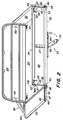
- the Loading platform 18 includes a horizontal plate or floor 20 and vertical right and left side walls 22, a front one Wall 24 and a rear wall 26.
- the wall 26 forms the rear wall of the loading platform 18 and is in one too descriptive way arranged to open the opening between the rear edges of the bottom 20 and the can close side walls 22.
- the side walls 22 are also such in a manner to be described arranged to be horizontally extending horizontally Can pivot axes.
- the rear wall 26 contains - starting from it upright position - an upright plate 28 with a bent upper edge 30 and a bent lower edge 32.
- a locking area 27 in the form of an open ended U-channel is welded to the upright plate 28.
- Opposing ends 33 of the rear wall 26 are each determined by an end plate 35 of the wall 26, the one main straight section 36 and a holder 37 for Holding the side wall 22 has.
- a bracket 38 of the wall 26 is attached to the floor 20 and takes a pivot pin 40, which is further through an opening in the End plate 35 of the wall 26 extends.
- the pivot pin 40 will through a screw connection with a nut attached to the Inside of the end plate 35 is welded, and the attachment of the Head of the pivot pin 40 held on the holder 38.
- the Pivot pins 40 at each end of the rear wall 26 represent one generally horizontal axis about which wall 26 pivots can.
- the rear wall 26 also includes a latch 50 at each end 33 which has an L-shaped rod 52 which for axial movement enclosed in a hole in one Holder 54 is guided, which is fixed to the plate 28 and extends from this backwards, one to the inside the end plate 35 welded sleeve and an aligned Opening in end plate 35 of wall 26.
- a spring 56 is caught between the holder 54 and a bolt which itself extends through a transverse bore in the rod 52 such that the rod 52 is biased to a position in which one end of the rod 52 outwards over the end plate 35 of the Wall 26 extends.
- a swivel arm 60 on the frame 12 of the transport vehicle 10 assembled.
- the swivel arm 60 is attached by means of a screw 62 a holder 63 attached to the frame 12 such that the Swing arm 60 about a generally vertical axis can, namely between a reserve position in which the Swivel arm 60 extends laterally and below the floor 20 is located, and a support position in which the Swing arm 60 extends longitudinally and one Locking section 64 rearward over the rear wall 26 extends if one from their closed position going out.
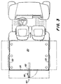
- Figure 3 shows the swivel arm 60 in its Support position and the relevant positions of the rear wall 26 and the side walls 20 in their closed and open (represented by the interrupted Lines) positions.
- the swivel arm 60 is preferably with a handle 66 provided by an operator can be taken to swing arm 60 between its Reserve and its support position to pivot.
- the holder 63 contains a swivel stop 68, which is for an attachment to the Swivel arm 60 in both the reserve and in the Support position of the swivel arms 60 ensures that the Operator the swivel arm 60 between in a simple manner can move these positions.
- a locking hook 70 is at the distal end 72 of the Swivel arm 60 mounted by means of a screw 74, which as Axis of rotation for the locking hook 70 is used.
- the Locking hook 70 is welded to a sleeve 71, the surrounds the screw 74 so that the locking hook 70 in the Desired position can be held on the screw 74.
- Discs 73 made of nylon are at each end of the sleeve 71 provided to build up a friction that is required to demand a desired level of strength to the To pivot locking hook 70.
- a handle 78 extends away from the locking hook 70 so that an operator can turn the locking hook 70 more easily around the wall 26 lock in the open position.
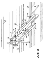
- a support bracket 75 is on a rail 15 of the frame 12 of the loading platform 18th mounted adjacent a near end 77 of the swivel arm 60, when the swivel arm 60 is in its support position (FIG. 5) located to support the near end 77 of the swing arm 60 to offer to reduce the bending moments that it from the Screw 62 seen from there when the swivel arm 60 through the Wall 26 is loaded at its outer end 72.
- each of the side walls 22 on opposite front and rear ends end plates 42 which holes for Includes the pivot pin 41, which also from Holders 44 for the walls 22 are added, the Hold bracket 44 in place with respect to floor 20.
- the Swivel bolts 41 are connected by a screw connection welded nuts held in place like that Swivel bolts 40 for the rear wall 26.
- the swivel bolts 41 at each end of the walls 22 adjust in the same way Pair laterally spaced and in general horizontal axes around which the lateral Walls 22 can pivot.
- the end plates 42 on the rear ends of walls 22 each contain one Holding flange 46, which is welded to this. Like this in FIG.
- the holding flange 46 contains one Main section 47 extending from the end plate 42 of the side Wall 22 extends backward and curved portions 48, extending from the main section 47 backwards and outwards extend.
- the holding flange 46 is with a hole 45 for one Provide the purpose to be described.
- the swivel arm 60 from its reserve position (FIG. 4) to its support position (Fig. 5) is pivoted so that it extends backwards over the Wall 26 extends beyond - starting from the closed Position - if it is desired to open the wall 26 and in lock the open position.
- the L-shaped rods 52 can slide inwards (against the force of the spring) so that the ends of the rods 52 from engagement with the holes in the retaining flanges 46 of the Side walls 22 are removed. Then the wall 26 can after be pivoted down.
- the locking portion 27 abuts the top of the swing arm 60 when the rear wall 26 is an in essential horizontal orientation (their open position) occupies. It can thus be seen that the locking section 27 represents the surface of the rear wall 26, which is supported directly by the swivel arm 60.
- the Locking section 27 extends from the upright Plate 28 of wall 26 to ensure that rear wall 26 is aligned with the bottom 20 to extend from to form this when the rear wall 26 in their is in the open position and supported by the swivel arm 60 becomes.
- the wall 26 can then result from movement of the handle 78, causing a rotation of the locking hook 70 in the open End of the locking portion 27 causes in their open position.
- the locking hook 70 detects the bottom of the locking portion 27.
- a inner contour 76 of the locking hook 70 does not run along a constant radius around the screw 74 so that the Locking hook 70 acts as a cam that back wall 26 - About their locking section 27 - and the swivel arm 60th clamps with increasing force when the Locking hook 70 is pivoted.
- the locking hook Unlock 70 he can through an opening in the Locking section 27 are pivoted and on the Above the top of the swivel arm 60 (see FIG. 6).
- the L-shaped rods 52 are biased by the force of the spring 56 so that the ends of the Rods 52 in each of the holes 45 in the retaining flange 46 be housed, causing another pivotal movement of the wall 26 prevented.
- the attachment the inside of the side wall 22 on the rear wall 26 and the front wall 24, as well as a front Fuse assemblies 80 prevent wall 22 from following to pan inside. It can therefore be seen that the side walls 22 and rear wall 26 as one support each other when they are in their closed, upright position. If the rear wall 26 is closed, the swing arm 60th be pivoted into its reserve position.
- the side walls 22 are covered by the front Fuse assembly 80 worn and in its open and closed position at the front end of each side wall 22 (see Fig. 7-8).
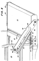
- the front fuse assembly 80 left wall 22 is shown in Figures 7-8.
- the front fuse assembly 80 of right wall 22 is from mirror image execution.
- the front fuse assembly 80 each includes a tab 82 which at one end of the End plate 42 of the wall 22 by means of a screw 83 and a Nut 104 is pivotally secured.
- the screw 83 is from surrounded by a sleeve that allows force to be drawn between the Nut 104 and the end plate 42 is transmitted so that a tight connection can be obtained without a Pivoting movement of the tab 82 around the screw 83 is prevented would.
- a sliding element 84 designed as a screw is through an opening in the front wall 24 and a corresponding one Opening in a reinforcement plate 85 shown in FIG. 2 mounted to effectively increase the thickness of the front wall 24 increase.
- the sliding element 84 and a sleeve that the Sliding element 84 surrounds are by means of a collar nut 87 in a slideway 86 of each tab 82 designed as a slot caught, so that the tab 82 opposite the sliding element 84th can slide and the sliding element 84 follows the sliding guide 86. It may be desirable to slide element 84 with one or to provide several disks 89 to act as a storage area for the Serve tab 82.
- the disks 89 serve the tab 82 at a distance from the front wall 24 to the tab 82 to keep substantially parallel to the wall 24 because the End plate 42 is preferably designed so that it is the front Wall 24 overlap to provide additional loading platform 18 To give strength when the side walls 22 in in their closed upright position.
- the disks 89 can be made from a low friction material be so that the relative sliding movement between the Sliding element 84 and the tab 82 a little effort required.
- the slideway 82 faces the inner and outer Ends 90, 92 of each slideway 82 are bent upward Section or stop 88, which act as a lock, each of which has an open and a closed position is assigned to the side wall 22.
- the openings in the front Wall 24 and reinforcement plate 85 are preferred elongated, so that the sliding element 84 for compensation adjusted by manufacturing tolerances in assigned parts can be.
- the sliding element 84 can be released, the side Wall 22 in tight fit on the outside of the front wall 24 brought up and the sliding element 84 tightened again become. This setting ensures that the closed upright position of the side wall 22 in a desired Relationship between the side wall 22 and the front wall 24 stands.
- a spring 94 is between a spring holder, such as one Rivet 96, and a tongue portion 98 of tab 82 inserted, rivet 96 shown attached to front wall 24 is.
- the spring 94 tensions the tab 82 downward so that lack of one applied by an operator counteracting force, the sliding element 84 in one of the after Above facing stops 88 is inserted, and the side Wall 22 is in the open or closed position held, the relevant upward-facing stop 88, in which the sliding element 84 sits is assigned.
- the tab 82 is with an outwardly bent region 100 in the manner of a Lip shown so that an operator the tab 82nd can more easily grip them against the force of the spring 94 to raise.
- Figure 7 shows the front fuse assembly 80 in Connection to the left wall 22 of the transport vehicle 10, wall 22 being shown in its closed position.
- the sliding element 84 is in the upward-facing stop 88 the tab 82 at the outer end 92 of the slideway 82 used what a pivoting movement of the side wall 22nd prevented.
- the side wall 22 can be closed in that the Tab 82 is raised to slide element 84 out of the post Above facing stop 88 on the inner end 90 of the slide 86 to solve.
- the side wall 22 can then go up be pivoted until it reaches its closed position, in which the sliding element 84 on the outer end 92 of the slideway 86 hits.
- the spring 94 then becomes the tab 82 down pull, so that the sliding element 84 in the upward directed stop 88 at the outer end 92 of the slide 86 puts.
- the swing arm 60 is in its support position pivoted and the rear wall 26 is in the previously described way open and in their open position with locked the swivel arm 60.
- the front fuse assembly 80 can then be handled in the manner previously described be so that the side walls 22 in their open Position can be taken while doing the conversion complete.
- the loading platform 18 can regress by first the side walls 22 and then the rear wall 26 in the manner described herein getting closed.
- buffer 102 such as e.g. B. nylon plugs, on the circumference of the bottom 20 and between to attach the rear and front walls 26 and 24.
- the buffers 102 serve to reduce the noise when there is the front and rear walls 22 and 26 in their closed, upright position.
Landscapes
- Engineering & Computer Science (AREA)
- Chemical & Material Sciences (AREA)
- Combustion & Propulsion (AREA)
- Transportation (AREA)
- Mechanical Engineering (AREA)
- Body Structure For Vehicles (AREA)
- Fittings On The Vehicle Exterior For Carrying Loads, And Devices For Holding Or Mounting Articles (AREA)
- Vehicle Step Arrangements And Article Storage (AREA)
Abstract
Description
- Fig. 1
- ein Transportfahrzeug in einer perspektivischen Ansicht von vorne links,
- Fig. 2
- eine Ladeplattform des Transportfahrzeugs in einer perspektivischen Ansicht von hinten links,
- Fig. 3
- eine Draufsicht auf das Transportfahrzeug nach Figur 1, wobei die durchgezogenen Linien die Ladeplattform in einem geschlossenen und die unterbrochenen Linien in einem geöffneten Zustand zeigen,
- Fig. 4
- die Ladeplattform in einer Ansicht von unten und hinten mit einem Schwenkarm zum Stützen einer rückwärtigen Wand in einer Reservestellung,
- Fig. 5
- die Ladeplattform in einer Ansicht von hinten und unten, wobei der Schwenkarm in einer Stützstellung geschwenkt ist,
- Fig. 6
- ein vertikaler Schnitt durch den Schwenkarm und einen Teil der auf ihm auf liegenden Wand,
- Fig. 7
- ein Sicherungszusammenbau zwischen einer vorderen und einer seitlichen Wand, wobei die seitliche Wand ihre geschlossene Stellung einnimmt, und
- Fig. 8
- den Sicherungszusammenbau aus Figur 7, wobei die seitliche Wand ihre geöffnete Stellung einnimmt.
Claims (8)
- Ladeplattform (18) eines Transportfahrzeugs (10) mit einem Boden (20), wenigstens einer stehenden Wand (24) und wenigstens einer schwenkbaren Wand (22), wobei zwischen der stehenden und der schwenkbaren Wand (24) und (22) ein Sicherungszusammenbau (80) vorgesehen ist, um die schwenkbare Wand (22) gegen eine Schwenkbewegung in einer Richtung zu sichern, dadurch gekennzeichnet, daß der Sicherungszusammenbau (80) eine Lasche (82) mit einer Gleitbahn (86) aufweist, wobei die Lasche (82) an einer der Wände (24, 22) schwenkbar angebracht ist, die Gleitbahn (86) von einem Gleitelement (84) durchdrungen wird, das Gleitelement (84) an der anderen Wand (24, 22) befestigt ist und die Gleitbahn (86) zwei Anschläge (88) aufweist, wobei das Gleitelement (84) bei einer Bewegung der Lasche (82) aufgrund einer Bewegung der schwenkbaren Wand (22) in der anderen Richtung an einem der Anschläge (88) zur Anlage kommt.
- Ladeplattform nach Anspruch 1, dadurch gekennzeichnet, daß die Gleitbahn (86) als ein Schlitz und das Gleitelement (84) als ein Schlitzfolgeelement, insbesondere als eine Schraube, ausgebildet ist, das die Gleitbahn (86) durchsetzt.
- Ladeplattform nach Anspruch 1 oder 2, dadurch gekennzeichnet, daß die Anschläge (88) durch Nasen oder Aussparungen an gegenuberliegenden Enden der Gleitbahn (86) gebildet werden.
- Ladeplattform nach einem oder mehreren der vorherigen Ansprüche, gekennzeichnet durch eine an die Lasche (82) angreifende Feder (94), die die Lasche (82) mit ihrer Gleitbahn (86) zur Anlage des Gleitelements (84) an einem der Anschläge (88) vorspannt.
- Ladeplattform nach einem oder mehreren der vorherigen Ansprüche, dadurch gekennzeichnet, daß die Lasche (82) plattenförmig ausgebildet ist.
- Ladeplattform nach einem oder mehreren der vorherigen Ansprüche, dadurch gekennzeichnet, daß die Lasche (82) mit einem abgekrümmten Bereich (100) versehen ist.
- Ladeplattform nach einem oder mehreren der vorherigen Ansprüche, dadurch gekennzeichnet, daß die Anschläge (88) durch die insbesondere rechtwinklige Führung der Gleitbahn (86) in deren Endbereich gebildet werden.
- Ladeplattform nach einem oder mehreren der vorherigen Ansprüche, dadurch gekennzeichnet, daß es sich bei der stehenden Wand (24) um eine auf einem Rahmen (12) befestigte vordere Wand (24) und bei der beweglichen Wand (22) um eine Seitenwand handelt, wobei sich das Gleitelement (84) sowohl in einer ausgeklappten im wesentlichen mit dem Boden (20) ebenen Stellung als auch in einer aufrechten und zu dem Boden (20) senkrechten Stellung der beweglichen Wand (22) an dem jeweiligen Anschlag (90, 92) anlegt.
Applications Claiming Priority (2)
| Application Number | Priority Date | Filing Date | Title |
|---|---|---|---|
| US292489 | 1994-08-18 | ||
| US09/292,489 US6048018A (en) | 1999-04-15 | 1999-04-15 | Cargo box sidewall latch |
Publications (2)
| Publication Number | Publication Date |
|---|---|
| EP1044868A2 true EP1044868A2 (de) | 2000-10-18 |
| EP1044868A3 EP1044868A3 (de) | 2003-05-07 |
Family
ID=23124897
Family Applications (1)
| Application Number | Title | Priority Date | Filing Date |
|---|---|---|---|
| EP00107425A Withdrawn EP1044868A3 (de) | 1999-04-15 | 2000-04-06 | Ladeplattform eines Transportfahrzeugs |
Country Status (4)
| Country | Link |
|---|---|
| US (1) | US6048018A (de) |
| EP (1) | EP1044868A3 (de) |
| AU (1) | AU758906B2 (de) |
| CA (1) | CA2297621A1 (de) |
Families Citing this family (20)
| Publication number | Priority date | Publication date | Assignee | Title |
|---|---|---|---|---|
| US6254159B1 (en) | 1999-08-12 | 2001-07-03 | Ardell G. Wieczorek | Offroad search and rescue vehicle |
| JP3378546B2 (ja) * | 1999-12-27 | 2003-02-17 | 川崎重工業株式会社 | 作業用四輪車 |
| KR100398435B1 (ko) * | 2000-10-30 | 2003-09-19 | 현대자동차주식회사 | 자동차의 테일 게이트 가이드 장치 |
| US6494520B2 (en) * | 2001-04-24 | 2002-12-17 | Ford Global Technologies, Inc. | Vehicle tailgate limiter system |
| JP3809954B2 (ja) * | 2002-10-23 | 2006-08-16 | 株式会社小松製作所 | チルトフロアを備えた作業車両 |
| US6910731B2 (en) * | 2002-12-19 | 2005-06-28 | Clark Equipment Company | Skid steer loader with front pivoting cab having a no tool latch |
| US20050093339A1 (en) * | 2003-10-30 | 2005-05-05 | Klassen Michael J. | Truck with folding sidewalls |
| CA2497613A1 (en) * | 2004-02-18 | 2005-08-18 | Dimiter S. Zagoroff | A system for counterbalancing a tailgate |
| US20070216195A1 (en) * | 2006-03-14 | 2007-09-20 | Textron Inc. | Plastic cargo bed |
| AU2009100536B4 (en) * | 2009-06-02 | 2010-03-25 | Vawdrey Australia Pty Ltd | Vehicle trailer with retractable barrier |
| US8075038B2 (en) * | 2009-11-26 | 2011-12-13 | Cary Russell Zielinsky | Multi-position tailgate support apparatus and method |
| US8469130B2 (en) * | 2011-02-18 | 2013-06-25 | Deere & Company | Cab stay |
| KR20140093932A (ko) * | 2011-10-25 | 2014-07-29 | 볼보 컨스트럭션 이큅먼트 에이비 | 건설기계의 엔진 후드 개폐장치 |
| KR101524763B1 (ko) * | 2013-10-04 | 2015-06-11 | 주식회사 호룡 | 고가 사다리차 |
| US10549793B2 (en) | 2014-12-31 | 2020-02-04 | Club Car, Llc | Latch mechanism |
| US10954704B2 (en) * | 2016-08-25 | 2021-03-23 | Greenlee Tools, Inc. | Door stop mechanism for holding a door of an enclosure in an open position |
| EP3381772B1 (de) | 2017-03-27 | 2020-10-21 | Ford Global Technologies, LLC | Seitenwand für eine ladefläche mit verbesserter verriegelung oder verbessertem verriegelungsmechanismus |
| CN107499394B (zh) * | 2017-08-15 | 2024-02-06 | 广东东箭汽车科技股份有限公司 | 车厢挡板助力装置及汽车车厢 |
| EP4274946A4 (de) * | 2021-01-07 | 2024-08-21 | Dickman, John | Leiterspreizer |
| IT202200014230A1 (it) * | 2022-07-05 | 2024-01-05 | Iveco Spa | Sistema di contenimento per sponda di un cassone di veicolo commerciale |
Citations (1)
| Publication number | Priority date | Publication date | Assignee | Title |
|---|---|---|---|---|
| US2278450A (en) | 1941-10-08 | 1942-04-07 | Byron Q Jones | Military vehicle body |
Family Cites Families (8)
| Publication number | Priority date | Publication date | Assignee | Title |
|---|---|---|---|---|
| US1122849A (en) * | 1914-03-14 | 1914-12-29 | Shearman Botteese | Truck. |
| US1636468A (en) * | 1926-08-14 | 1927-07-19 | Hunt Helm Ferris & Co | Door-holding attachment |
| US2561081A (en) * | 1946-12-06 | 1951-07-17 | George Harold Bell & Associate | Suspending, latching, and locking means for tail gates |
| AT328878B (de) * | 1972-08-28 | 1976-04-12 | Rhein Kraftfahrzeuge | Hebegerat fur fahrzeugbordwande |
| US4348045A (en) * | 1977-08-31 | 1982-09-07 | Jidosha Seiko Co., Ltd. | Device for opening and closing a side plate of a loading box on a motor truck under no-load condition |
| US4143904A (en) * | 1978-02-27 | 1979-03-13 | General Motors Corporation | Station wagon tailgate |
| US4580828A (en) * | 1985-02-13 | 1986-04-08 | Jones Charles W | Tailgate for a pickup truck |
| USD311856S (en) | 1988-08-22 | 1990-11-06 | Deere & Company | Tailgate latch |
-
1999
- 1999-04-15 US US09/292,489 patent/US6048018A/en not_active Expired - Lifetime
-
2000
- 2000-02-03 CA CA002297621A patent/CA2297621A1/en not_active Abandoned
- 2000-04-06 EP EP00107425A patent/EP1044868A3/de not_active Withdrawn
- 2000-04-11 AU AU27677/00A patent/AU758906B2/en not_active Ceased
Patent Citations (1)
| Publication number | Priority date | Publication date | Assignee | Title |
|---|---|---|---|---|
| US2278450A (en) | 1941-10-08 | 1942-04-07 | Byron Q Jones | Military vehicle body |
Also Published As
| Publication number | Publication date |
|---|---|
| EP1044868A3 (de) | 2003-05-07 |
| AU2767700A (en) | 2000-10-19 |
| CA2297621A1 (en) | 2000-10-15 |
| US6048018A (en) | 2000-04-11 |
| AU758906B2 (en) | 2003-04-03 |
Similar Documents
| Publication | Publication Date | Title |
|---|---|---|
| DE69500037T2 (de) | Vorrichtung zum Tragen von Gegenständen, insbesondere Fahrrädern, auf der Hinterseite eines Kraftfahrzeuges | |
| DE3500529C2 (de) | ||
| EP1044869A2 (de) | Ladeplattform eines Transportfahrzeugs | |
| DE4204712C2 (de) | Ausbaubarer Autositz | |
| CH635036A5 (de) | Verstellbare rueckenlehne eines sitzes. | |
| DE3731667A1 (de) | Einstellbarer traegeraufbau fuer einen gepaecktraeger | |
| DE7715948U1 (de) | In mindestens zwei teile zerlegbares moebel, insbesondere zur verwendung in caravans | |
| DE2804129A1 (de) | Portalschlepper | |
| DE10228314A1 (de) | Sitz-Schienenbaugruppe mit Einrastmechanismus | |
| DE3926367A1 (de) | Vorrichtung fuer eine traktorkupplung zur begrenzung von schlenkerbewegungen | |
| DE19616070C2 (de) | Kraftfahrzeugsitz | |
| EP0324974A1 (de) | Vorrichtung zum frontseitigen Anbau eines Arbeitsgerätes an einen Kleinschlepper, insbesondere Rasen- und Gartenschlepper | |
| DE1111866B (de) | Verbindungseinrichtung zwischen einem Schlepper und einem an diesen anzubauenden Arbeitsgeraet | |
| DE1918517A1 (de) | Hebebock oder -buehne | |
| DE2642456C2 (de) | ||
| DE3100405A1 (de) | Tierfalle | |
| DE102018108079A1 (de) | Lenkeranordnung für einen Dreipunkt-Kraftheber eines Traktors oder einer sonstigen landwirtschaftlichen Arbeitsmaschine sowie Dreipunkt-Kraftheber | |
| DD264136A1 (de) | Klappgelenk fuer aussenrahmen von bodenbearbeitungsgeraeten | |
| DE102006023179A1 (de) | Anbauvorrichtung für eine Landmaschine | |
| DE2630375C2 (de) | Türanordnung, insbesondere für Behälter, Behälterwagen o.dgl. | |
| DE1963641A1 (de) | Fahrzeug zum Transport von Erde und anderen Materialien | |
| DE2829653A1 (de) | Vorrichtung zum festhalten der beiden teile einer kabinentuer von traktoren, gleiskettenfahrzeugen o.dgl. in einer belueftungsstellung | |
| DE3301460A1 (de) | Vorrichtung zum befestigen eines arbeitgeraetes an einem fahrzeug | |
| AT376178B (de) | Ladevorrichtung fuer transportfahrzeuge | |
| DE2435477B1 (de) | Geräteanbauvorrichtung mit Abstützung der Oberlenker gegenüber den Unterlenkern durch Blattfedern, insbesondere für einen Schlepper |
Legal Events
| Date | Code | Title | Description |
|---|---|---|---|
| PUAI | Public reference made under article 153(3) epc to a published international application that has entered the european phase |
Free format text: ORIGINAL CODE: 0009012 |
|
| AK | Designated contracting states |
Kind code of ref document: A2 Designated state(s): AT BE CH CY DE DK ES FI FR GB GR IE IT LI LU MC NL PT SE |
|
| AX | Request for extension of the european patent |
Free format text: AL;LT;LV;MK;RO;SI |
|
| PUAL | Search report despatched |
Free format text: ORIGINAL CODE: 0009013 |
|
| AK | Designated contracting states |
Designated state(s): AT BE CH CY DE DK ES FI FR GB GR IE IT LI LU MC NL PT SE |
|
| AX | Request for extension of the european patent |
Extension state: AL LT LV MK RO SI |
|
| AKX | Designation fees paid | ||
| REG | Reference to a national code |
Ref country code: DE Ref legal event code: 8566 |
|
| STAA | Information on the status of an ep patent application or granted ep patent |
Free format text: STATUS: THE APPLICATION IS DEEMED TO BE WITHDRAWN |
|
| 18D | Application deemed to be withdrawn |
Effective date: 20031101 |