EP1040069B1 - Fadenliefergerät - Google Patents
Fadenliefergerät Download PDFInfo
- Publication number
- EP1040069B1 EP1040069B1 EP98966362A EP98966362A EP1040069B1 EP 1040069 B1 EP1040069 B1 EP 1040069B1 EP 98966362 A EP98966362 A EP 98966362A EP 98966362 A EP98966362 A EP 98966362A EP 1040069 B1 EP1040069 B1 EP 1040069B1
- Authority
- EP
- European Patent Office
- Prior art keywords
- feeler
- feeler arm
- feeding device
- projection
- sensor
- Prior art date
- Legal status (The legal status is an assumption and is not a legal conclusion. Google has not performed a legal analysis and makes no representation as to the accuracy of the status listed.)
- Expired - Lifetime
Links
Images

Classifications
-
- B—PERFORMING OPERATIONS; TRANSPORTING
- B65—CONVEYING; PACKING; STORING; HANDLING THIN OR FILAMENTARY MATERIAL
- B65H—HANDLING THIN OR FILAMENTARY MATERIAL, e.g. SHEETS, WEBS, CABLES
- B65H51/00—Forwarding filamentary material
- B65H51/20—Devices for temporarily storing filamentary material during forwarding, e.g. for buffer storage
- B65H51/22—Reels or cages, e.g. cylindrical, with storing and forwarding surfaces provided by rollers or bars
-
- D—TEXTILES; PAPER
- D03—WEAVING
- D03D—WOVEN FABRICS; METHODS OF WEAVING; LOOMS
- D03D47/00—Looms in which bulk supply of weft does not pass through shed, e.g. shuttleless looms, gripper shuttle looms, dummy shuttle looms
- D03D47/34—Handling the weft between bulk storage and weft-inserting means
- D03D47/36—Measuring and cutting the weft
- D03D47/361—Drum-type weft feeding devices
- D03D47/367—Monitoring yarn quantity on the drum
-
- B—PERFORMING OPERATIONS; TRANSPORTING
- B65—CONVEYING; PACKING; STORING; HANDLING THIN OR FILAMENTARY MATERIAL
- B65H—HANDLING THIN OR FILAMENTARY MATERIAL, e.g. SHEETS, WEBS, CABLES
- B65H2601/00—Problem to be solved or advantage achieved
- B65H2601/50—Diminishing, minimizing or reducing
- B65H2601/52—Diminishing, minimizing or reducing entities relating to handling machine
- B65H2601/524—Vibration
Definitions
- the invention relates to a thread delivery device which in the preamble of claim 1 specified type.
- the invention has for its object a yarn delivery device of the aforementioned Type to create, which is characterized by a compact sensor device with a precise and insensitive responsiveness.
- the projection covers the scanning distance not only by one-way movement from one side, but the projection also works with the Cover area together, that the scanning distance first from the cover area the side opposite the penetration side of the projection into the scanning path is exactly limited, and when the projection passes through the scanning path finally the overlap between the cover edge and the cover surface is established is that a quick and complete coverage of the scanning distance with a sharp transition.
- the scanning path is, so to speak, two opposite ones Sides narrowed here (in the manner of a slit diaphragm) and ultimately completely interrupted. It is structurally simply a clean signal transition Scanning device achieved when the cover edge overlaps the cover surface and reliably interrupts the scanning path.
- the flag is an actuator of the scanning device in the sensor arm or integrated sensor arm part. It can perform an additional function if it determines the end position with the stop.
- the stroke shapes simple at the same time on the cover surface.
- the overlap is narrow transversely to the direction of the sensor arm Space.
- the flag serves as a carrier of the lead and assists the coverage of the scanning distance.
- the scanning distance is particularly simple and effectively limited and blocked.
- optodetector For scanning is preferred according to claim 5 in a fork-shaped holder housed optodetector used, which is inexpensive with high operational reliability is and works precisely.
- the optodetector can be placed protected.
- optodetector is only one way of tapping the movements of the Feeler. It could also be an inductive, an electrical, or an electromagnetic or a pneumatic detector can be used.
- Output signals from the scanner are expedient for controlling the drive of the thread delivery device or for error monitoring of the thread delivery device or a thread processing system used to which the thread delivery device belongs.
- the bracket of the Optodetector can be arranged on a circuit board in the sensor housing, the PCB acts as a cover inside the sensor housing to the outside. Possibly even forms a stroke limiter for the sensor arm.
- One for the feeler foot The passage opening provided can be small, so that dirt can hardly penetrate or simple measures are sufficient to prevent the ingress of dirt to avoid reliably.
- the spring element has the task of loading regardless of the installation position of the thread delivery device to generate the sensor arm to the basic position, and in addition the emergence of swinging movements of the sensor arm under unfavorable operating conditions steam, if necessary as soon as they arise. This is achieved through a spring hardening in a movement range of the sensor arm into which he can get due to his work dynamics.
- the forced Damping prevents an undesirable rocking effect without the work of the Affect sensor arms. Conversely, damping improves correct working of the feeler arm when sensing the presence or absence of the thread.
- the suspension of the sensor arm and the aforementioned Damping accomplished in a structurally simple manner.
- the response behavior of the sensor device is improved, if the guide arm is in the stationary guide fork in unfavorable operating conditions guided or at least supported against lateral evasive movements becomes. Lateral vibrations of the guide arm can already be created dampen.
- the scanning device and the spring arrangement on the same Side of the bearing are integrated in the sensor housing, like the sensor foot supporting feeler arm part, becomes significant in the direction of the axis of the storage drum Construction space saved. Furthermore, the number of necessary individual parts of the Sensor device noticeable. There is also installation space transverse to the axis of the storage drum saved because the individual cooperating parts are arranged close to each other can be. This is advantageous if the sensor device has multiple sensor arms Is provided. Thanks to the compact arrangement, harmful vibrations avoided, so that a sensitive response can be achieved.
- the number of individual parts can be reduced in a small installation space, if each probe arm part directly with its scanning device and the spring arrangement interacts, i.e. without additional, motion-transmitting accessories.
- the scanning device facing away from the sensor base Side of the bearing can be arranged, the sensor arms accordingly extended beyond storage to the other side.
- the scanner can then expediently on a control board of a drive of the thread delivery device to be assembled. It is true in the direction of the axis of the storage drum takes up more space; however, the scanner can then be influenced by Better remove dirt or lint.
- a weight balance for the Sensor arm achieved. If necessary, it can be very wear-resistant, but something use heavier, feeler feet without problems, without undesirably high mechanical To generate loads on the thread.
- the sensor arm part is already with the flag and the stop for prepared the cooperation with the cover device and the spring arrangement. This has manufacturing advantages.
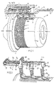
- Fig. 1 is from a yarn delivery device F (weft delivery device for a weaving machine) a winding element 1 shown in a storage drum 2, which one a housing or a housing bracket 4 attached sensor device S assigned.
- three sensor arms A are provided, which are extend parallel to each other in the direction of the axis of the storage drum 2 and one yarn supply V consisting of turns of a yarn Y on the storage drum 2 monitor.
- the thread supply V is a relative rotary movement between the winding element 1 and the storage drum 2 (in the present case a stationary storage drum 2) with an axial size, which regulates is emptying despite continuous or intermittent thread consumption or to avoid overfilling the storage drum 2.
- the thread supply V spills over a longitudinal recess 3 in the storage drum 2.
- feeler feet 8a to 8c aligned are durable, in which he engages in the recess 3 and on which he through the thread supply V can be shifted upwards.
- the left foot 8a in FIG Thread break guard should be included, which responds as soon as the first turns of the thread supply V fail to appear.
- the sensor base 8b can belong to a minimal sensor, which monitors the minimum permissible size of the thread supply V and in the absence the thread supply V activates the drive of the winding element 1 in this area, to supplement the thread supply V.
- the feeler foot 8c belongs to one, for example the so-called maximum sensor, which when shifting from that shown in FIG. 1 Home position switches off or delays the drive of the winding element 1 because the permissible maximum size of the thread supply V has been reached.
- each sensor arm A consists of a sensor arm part 7a to 7c and the sensor foot 8a to 8c. These components can be manufactured separately and together be connected. All sensor arms A are on a common axis 5 in one Sensor housing 6 mounted, the axis 5 being approximately transverse to the direction of Axis of the storage drum 2 extends. Alternatively, it would be possible to have axis 5 parallel arrange to the axis of the storage drum 2, and the sensor arms A transverse to the axis to orient the storage drum 2.
- a spring arrangement B is provided, which is a switching device D is assigned.
- the sensor housing 6 is, for example, in the arm 4 of the thread delivery device housing integrated.
- Each sensor arm A is non-contact Assigned scanning device T, which depends on the pivoting position of the sensor arm generates a signal for an associated monitoring or control device.
- the scanning device T can be an optoelectronic, electrical, electronic or electromagnetic detector.
- the spring arrangement B and the scanning device T are the same in FIGS. 1 to 3 Side of the axis 5 arranged like the feeler arm parts carrying the feeler feet 8a to 8c 7a to 7c.
- the scanning devices T are below and the spring arrangement T above the sensor arm parts 7a to 7c.
- each sensor arm part 7a to 7c is a molded part, e.g. made of plastic (injection molded part), is in which a jack 9 for the sensor base 8a to 8c, a stop 14 for the Spring arrangement B and a flag 13 for the scanning device T structurally integrated are.
- the sensor device S more or less than the three sensor arms A shown.
- the sensor feet 8a to 8c are identical in the embodiment shown.
- everybody Feet base 8a to 8c is, for example, a molded metal part, e.g. a die cast part or out Spring steel wire bent, with a toe defining a continuous surface 10 and two approximately parallel and spaced legs 11, one of which a leg 11 is inserted into the respective jack 9 of a sensor arm part 7a to 7c and, if necessary, secured in position by means of a securing element 20 is.
- the other leg 11 ends freely or is of the required length shortened.
- the width of each sensor foot 8a to 8c is larger than the distance between adjacent sensor arm parts 7a to 7c, made possible by a lateral displacement the jack 9 on the sensor arm part 7b. If necessary, the jacks 9 adjustable on the feeler arm parts 7a to 7c in the longitudinal direction thereof to be able to adjust the relative positions of the sensor feet 8a to 8c.
- a stationary guide fork 12 can be assigned to each sensor arm part 7a to 7c be between the teeth of the sensor arm part 7a to 7c out or at least lateral evasion is prevented.
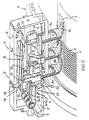
- the stops 14 on the feeler arm parts 7a to 7c are at the same distance from the axis 5 and bear on the top rounded surfaces 15 which on spring elements 16a to 16c of the spring arrangement B rest around each sensor foot 8a to 8c in its basic position (see the right one in FIG. 2 Feeler foot 8c) to keep resilient until he is by the rear force of the Thread Y is shifted from the basic position.
- the spring elements shown in Fig. 2 16a to 16c expediently belong to a single spring element which at 17 is anchored in the sensor housing.
- the spring elements 16a to 16c are flexible springs, expediently leaf springs that project freely.
- the switching device D contains for each spring element 16a to 16c an expediently adjustable damping extension 18, e.g. a set screw that is accessible from outside the sensor housing 6 and on a contact area 19 with the associated spring element 16a up to 16c.
- the spring elements 16a to 16c do not necessarily come into contact with the damping extension 18. Only when a larger stroke of the sensor arm due to the dynamics A should occur, its spring element 16a to 16c comes against the damping extension 18. Since its contact area 19, for example at that of the anchoring 17 faces away from the surface 15, the spring element 16a to 16b hardens clearly dampened by the swinging movement of the sensor arm A and this in his normal working area is pushed back.
- the scanning devices T are arranged on a circuit board, for example Has through openings 32 for the legs 11 of the sensor feet 8a to 8c and Conductor tracks and possibly other electronic or electrical components wearing.
- Fig. 3 is a cut end 21 of a leg 11 of a feeler foot 8c indicated. This cut end 21 could be used when planted on the underside of the board P an upward stroke limitation for the assigned one Form sensor arm A. Furthermore, it can be seen in Fig. 8 that each flag 13 on the underside of the sensor arm part 7a to 7c is formed and corresponding to FIGS. 4 and 5 serves, among other things, the basic position of each sensor arm part 7a to 7c in cooperation limit with a stationary stop 30.
- an optoelectronic detector of the scanning device T is formed of an emitter E and a receiver R aligned thereon, between which a beam path 23 is present as a scanning path.
- the scanning device T is in a For example, integrated on the board B, fork-shaped bracket 24 integrated.
- the Bracket has a mouth-shaped recess 25 for the flag 13, for example the Feeler arm part 7a.
- the stop 30 is formed by an insert 26.
- a recess 27 is provided on both sides is limited by cover surfaces 29 and one on the underside of the flag 13 provided projection 28 allows in the position shown in Fig. 4 in the recess immerse. This position is defined by laying the lower side the flag 13 on the stop 30.
- the scanning device T is either in the position shown in FIG. 4 or in the 5 generates a signal that the control or monitoring device registered and evaluated.
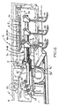
- the sensor arms A are beyond the common axis 5 with sensor arm parts 7a ', 7b', 7c 'and the scanning device T is on the sensor feet 8a, 8b, 8c side of the axis 5 facing away, e.g. in a board P ' the drive control of the thread delivery device F containing section 6 of the boom 4.
- the brackets 24 of the scanning device T can be arranged on this board P. his.
- the stops 30 for the flags 13 on the sensor arm parts 7a 'to 7c' are formed by projections 33 which penetrate the board P 'and expedient are integrally formed with the section 6 ', which belongs to the boom 4.
- the sensor arm parts 7a 'to 7c' can be designed as ballast masses G or (as shown) Have ballast mass G. Although not highlighted in Fig. 6, it works each flag 13 analogous to FIGS. 4 and 5 with a projection 28 and at least a cover edge 31 overlapping with at least one formed by the stop 30 Cover surface 29 together when the beam path 23 is shadowed.
- the switching device D has permanently installed damping extensions 18 in FIG. 6.
- the Preload of the spring arrangement B anchored at 17 can be adjusted centrally by means of an adjusting screw 34 which, for example, is arranged in the sensor housing 6.
- the sensor housing 6 is housed in the boom 4.
Landscapes
- Engineering & Computer Science (AREA)
- Textile Engineering (AREA)
- Knitting Machines (AREA)
- Looms (AREA)
- Length Measuring Devices With Unspecified Measuring Means (AREA)
- Unwinding Of Filamentary Materials (AREA)
- Forwarding And Storing Of Filamentary Material (AREA)
- Feeding Of Articles To Conveyors (AREA)
Description
- Fig. 1
- eine schematische und perspektivische Teilschnittansicht von Hauptkomponenten eines Fadenliefergeräts,
- Fig. 2
- eine perspektivische Teilschnittdarstellung ähnlich der von Fig. 1 in vergrößertem Maßstab,
- Fig. 3
- einige Komponenten aus den Fig. 1 und 2 in perspektivischer Darstellung und herausgelöst aus dem Gesamtverbund,
- Fig. 4
- einen Querschnitt eines Details in einer Endstellung eines Fühlerarmteils,
- Fig. 5
- einen Querschnitt entsprechend Fig. 4, in einer anderen Stellung des Fühlerarmteils, und
- Fig. 6
- eine perspektivische Teilschnittdarstellung ähnlich der von Fig. 2 bei einer weiteren Ausführungsform.
Claims (14)
- Fadenliefergerät (F) mit einer Speichertrommel (2) für einen aus Windungen eines Fadens (Y) bestehenden Fadenvorrat (V), mit einer außerhalb der Speichertrommel in einem Sensorgehäuse (6) angeordneten Sensorvorrichtung, die wenigstens einen in einer Lagerung (5) beweglichen Fühlerarm (A) aufweist, der sich von der Lagerung (5) mit einem einen Fühlerfuß (8a bis 8c) tragenden Fühlerarmteil (7a bis 7c) in den Bewegungsweg der Windungen entlang der Speichertrommel erstreckt und von diesen aus einer Grundstellung verlagerbar ist, mit einer den Fühlerarm in einer Bewegungsrichtung beaufschlagenden Federanordnung (B), und mit einer signalerzeugenden, berührungslosen Abtastvorrichtung (T) für die Stellung des Fühlerarms, der stellungsabhängig eine Abtaststrecke (23) der Abtastvorrichtung abdeckt und freigibt, dadurch gekennzeichnet, dass am Fühlerarm (A) ein eine Abdeckkante (31) aufweisender Vorsprung (13, 28) angeordnet und mit dem Fühlerarm (A) durch die Abtaststrecke (23) hindurch bewegbar ist, und dass benachbart zur Abtaststrecke (23) und seitlich neben dem Bewegungsweg des Vorsprungs (13, 12) wenigstens eine Abdeckfläche (29) für den Vorsprung (13, 28) stationär angeordnet ist, so dass die Abdeckkante (31) und die Abdeckfläche (29) quer zur Abtaststrecke (23) in eine gegenseitige Überlappungsstellung bringbar sind.
- Fadenliefergerät nach Anspruch 1, dadurch gekennzeichnet, daß am Fühlerarm (A) bzw. einem Fühlerarmteil (7a bis 7c, 7a' bis 7c') eine den Vorsprung (28) tragende Fahne (13) zum Abdecken der Abtaststrecke (23) angeordnet ist, und daß der Fühlerarm (A) bzw. die Fahne (13) auf einen eine Endstellung begrenzenden, die Abdeckfläche (29) aufweisenden Anschlag (30) aufsetzbar ist.
- Fadenliefergerat nach Anspruch 2, dadurch gekennzeichnet, daß im Anschlag (30) für den Vorsprung (28) eine zwei gegenüberliegende Abdeckflächen (29) bildende Eintauchvertiefung (27) vorgesehen ist.
- Fadenliefergerät nach Anspruch 2, dadurch gekennzeichnet, daß der Anschlag (30) ein Einsatz (26) in einer gabelförmigen Optodetektor-Halterung (24) ist, deren Abtaststrecke (23) ein abschattbarer Strahlengang ist.
- Fadenliefergerät nach Anspruch 2, dadurch gekennzeichnet, daß der Anschlag (30') ein von einem Gehäuseteil (4) des Fadenliefergeräts (F) vorstehender, vorzugsweise mit dem Gehäuseteil einstückiger, Vorsprung (33) ist, der die die Abdeckfläche (29) bildende Eintauchvertiefung (27) für den Vorsprung (28) aufweist.
- Fadenliefergerät nach Anspruch 1, dadurch gekennzeichnet, daß die Federanordnung (B) ein Federelement (16a bis 16c) und eine federwegabhängige Umschaltvorrichtung (D) aufweist, mit der ab einem vorbestimmbaren Bewegungsweg des Fühlerarms (A) aus der Grundstellung eine Federkrafterhöhung bzw. Federverhärtung des Federelementes (16a bis 16c) einstellbar ist.
- Fadenliefergerät nach Anspruch 6, dadurch gekennzeichnet, daß das Federelement (16a bis 16c) eine frei auskragende Biege-Blattfeder ist, die den Fühlerarm permanent beaufschlagt, und daß an der dem Fühlerarm abgewandten Seite des Federelements ein die Umschaltvorrichtung (D) bildender Dämpffortsatz (18) auf das Federelement ausgerichtet ist, dessen Angriffspunkt (19) am Federelement in Längsrichtung des Federelements gegenüber dem Angriffspunkt des Fühlerarms am Federelement versetzt ist.
- Fadenliefergerät nach Anspruch 1, dadurch gekennzeichnet, daß für jeden Fühlerarm (A) eine stationäre Führungsgabel (12) vorgesehen ist, deren Zinken den Fühlerarm (A) in dessen Bewegungsrichtungen zur und aus der Grundstellung führen.
- Fadenliefergerat nach Anspruch 1, dadurch gekennzeichnet, daß die Federanordnung (B) und die Abtastvorrichtung (T) auf derselben Seite der Lagerung (5) angeordnet sind wie der den Fühlerfuß (8a bis 8c) tragende Fühlerarmteil (7a bis 7c).
- Fadenliefergerät nach Anspruch 10, dadurch gekennzeichnet, daß die Abtastvorrichtung (T) und die Federanordnung (B) im Bewegungsweg des Fühlerarms an gegenüberliegenden Seiten angeordnet sind.
- Fadenliefergerät nach Anspruch 1, dadurch gekennzeichnet, daß die Abtastvorrichtung (T) an der dem Fühlerfuß (8a bis 8c) abgewandten Seite der Lagerung (5), vorzugsweise auf einer Steuerungsplatine (P) eines Antriebs des Fadenliefergeräts (F), angeordnet ist, und daß der Fühlerarm (A) mit seinem die Fahne (13) und den Vorsprung (28) tragenden Fühlerarmteil (7a', 7b', 7c') von der Lagerung (5) zur Abtastvorrichtung (T) reicht.
- Fadenliefergerät nach Anspruch 11, dadurch gekennzeichnet, daß der Fühlerarmteil (7a', 7b', 7c') als Ausgleichsmasse (G) ausgebildet oder mit einer Ausgleichsmasse (G) versehen ist.
- Fadenliefergerät nach Anspruch 2, dadurch gekennzeichnet, daß die Fahne (13) und ein Anschlag (14) für die Federanordnung (B) am Fühlerarmteil (7a bis 7c) vorgesehen sind.
- Fadenliefergerät nach Anspruch 1, dadurch gekennzeichnet, daß die Sensorvorrichtung (S) mindestens zwei, vorzugsweise drei, nebeneinanderliegende Fühlerarme (A) mit unterschiedlich langen, auf einer gemeinsamen Achse (5) gelagerten Fühlerarmteilen (7a bis 7c, 7a' 7b'; 7c') aufweist, und daß die Federanordnung (B) der Anzahl der Fühlerarme (A) entsprechend viele einzelne Federelemente (16a bis 16c) für die Fühlerarme oder ein einziges, alle Fühlerarme beaufschlagendes Federelement umfaßt.
Applications Claiming Priority (3)
| Application Number | Priority Date | Filing Date | Title |
|---|---|---|---|
| DE19756243A DE19756243A1 (de) | 1997-12-17 | 1997-12-17 | Fadenliefergerät |
| DE19756243 | 1997-12-17 | ||
| PCT/EP1998/008299 WO1999030999A1 (de) | 1997-12-17 | 1998-12-17 | Fadenliefergerät |
Publications (2)
| Publication Number | Publication Date |
|---|---|
| EP1040069A1 EP1040069A1 (de) | 2000-10-04 |
| EP1040069B1 true EP1040069B1 (de) | 2002-08-07 |
Family
ID=7852334
Family Applications (3)
| Application Number | Title | Priority Date | Filing Date |
|---|---|---|---|
| EP98966362A Expired - Lifetime EP1040069B1 (de) | 1997-12-17 | 1998-12-17 | Fadenliefergerät |
| EP98965279A Expired - Lifetime EP1040067B1 (de) | 1997-12-17 | 1998-12-17 | Fadenliefergerät |
| EP98966967A Expired - Lifetime EP1047819B1 (de) | 1997-12-17 | 1998-12-17 | Fadenliefergerät |
Family Applications After (2)
| Application Number | Title | Priority Date | Filing Date |
|---|---|---|---|
| EP98965279A Expired - Lifetime EP1040067B1 (de) | 1997-12-17 | 1998-12-17 | Fadenliefergerät |
| EP98966967A Expired - Lifetime EP1047819B1 (de) | 1997-12-17 | 1998-12-17 | Fadenliefergerät |
Country Status (6)
| Country | Link |
|---|---|
| US (1) | US6409114B1 (de) |
| EP (3) | EP1040069B1 (de) |
| KR (2) | KR100368459B1 (de) |
| CN (3) | CN1098798C (de) |
| DE (4) | DE19756243A1 (de) |
| WO (3) | WO1999030998A1 (de) |
Families Citing this family (6)
| Publication number | Priority date | Publication date | Assignee | Title |
|---|---|---|---|---|
| ITTO20050484A1 (it) * | 2005-07-14 | 2007-01-15 | L G L Electronics Spa | Unita' di controllo per dispositivi di frenatura del filato in alimentatori di trama per telai di tessitura, e procedura di sintonizzazione della stessa |
| ITTO20050810A1 (it) * | 2005-11-18 | 2007-05-19 | Lgl Electronics Spa | Rilevatore di scorta trama per dispositivi alimentatori di trama |
| ITTO20050893A1 (it) * | 2005-12-22 | 2007-06-23 | Lgl Electronics Spa | Rilevatore di scorta trama perfezionato per dispositivi alimentari di trama |
| IT1402928B1 (it) * | 2010-12-13 | 2013-09-27 | Roj S R L | Porgitrama per telaio tessile |
| CN113862848A (zh) * | 2021-10-28 | 2021-12-31 | 那坡同益新丝绸科技实业有限公司 | 一种用于细纱机的夹纱装置 |
| IT202400004420A1 (it) * | 2024-02-29 | 2025-08-29 | Roj S R L | Porgitrama per telai di tessitura comprendente un gruppo ottico indipendente, integrato nel gruppo elettromagnete di rilascio del filo di trama |
Family Cites Families (7)
| Publication number | Priority date | Publication date | Assignee | Title |
|---|---|---|---|---|
| GB1345648A (en) * | 1971-04-29 | 1974-01-30 | Lawson Hemphill | Yarn storage feeders |
| US3776480A (en) * | 1972-04-05 | 1973-12-04 | Lawson Hemphill | Yarn handling apparatus |
| US3844504A (en) * | 1972-04-05 | 1974-10-29 | Lawson Hemphill | Method and apparatus for handling yarn |
| US3759455A (en) * | 1972-09-28 | 1973-09-18 | Wesco Industries Corp | Filament feeding and storage device |
| US4226379A (en) * | 1979-12-06 | 1980-10-07 | Leesona Corporation | Loom storage feeder improvement |
| BE900492A (nl) * | 1984-09-04 | 1985-03-04 | Picanol Nv | Snelheidsregeling van inslagvoorafwikkelaar bij weefgetouwen. |
| ITTO980520A1 (it) * | 1998-06-16 | 1999-12-16 | Lgl Electronics Spa | Perfezionamento ai dispositivi di sorveglianza della riserva di filato negli apparecchi alimentatori di trama a telai di tessitura. |
-
1997
- 1997-12-17 DE DE19756243A patent/DE19756243A1/de not_active Withdrawn
-
1998
- 1998-12-17 WO PCT/EP1998/008298 patent/WO1999030998A1/de not_active Ceased
- 1998-12-17 EP EP98966362A patent/EP1040069B1/de not_active Expired - Lifetime
- 1998-12-17 KR KR10-2000-7006640A patent/KR100368459B1/ko not_active Expired - Fee Related
- 1998-12-17 DE DE59805557T patent/DE59805557D1/de not_active Expired - Fee Related
- 1998-12-17 EP EP98965279A patent/EP1040067B1/de not_active Expired - Lifetime
- 1998-12-17 CN CN98813135A patent/CN1098798C/zh not_active Expired - Lifetime
- 1998-12-17 WO PCT/EP1998/008301 patent/WO1999031308A2/de not_active Ceased
- 1998-12-17 CN CN98812320A patent/CN1099364C/zh not_active Expired - Lifetime
- 1998-12-17 WO PCT/EP1998/008299 patent/WO1999030999A1/de not_active Ceased
- 1998-12-17 US US09/581,693 patent/US6409114B1/en not_active Expired - Fee Related
- 1998-12-17 KR KR10-2000-7006641A patent/KR100368460B1/ko not_active Expired - Fee Related
- 1998-12-17 CN CN98812318A patent/CN1108270C/zh not_active Expired - Lifetime
- 1998-12-17 EP EP98966967A patent/EP1047819B1/de not_active Expired - Lifetime
- 1998-12-17 DE DE59805136T patent/DE59805136D1/de not_active Expired - Fee Related
- 1998-12-17 DE DE59805134T patent/DE59805134D1/de not_active Expired - Lifetime
Also Published As
| Publication number | Publication date |
|---|---|
| KR100368460B1 (ko) | 2003-01-24 |
| CN1099364C (zh) | 2003-01-22 |
| EP1047819B1 (de) | 2002-09-11 |
| US6409114B1 (en) | 2002-06-25 |
| EP1047819A2 (de) | 2000-11-02 |
| KR20010033231A (ko) | 2001-04-25 |
| CN1108270C (zh) | 2003-05-14 |
| CN1282304A (zh) | 2001-01-31 |
| EP1040067B1 (de) | 2002-08-07 |
| DE59805557D1 (de) | 2002-10-17 |
| KR20010033232A (ko) | 2001-04-25 |
| CN1285803A (zh) | 2001-02-28 |
| EP1040067A1 (de) | 2000-10-04 |
| EP1040069A1 (de) | 2000-10-04 |
| KR100368459B1 (ko) | 2003-01-24 |
| CN1098798C (zh) | 2003-01-15 |
| DE59805134D1 (de) | 2002-09-12 |
| DE19756243A1 (de) | 1999-06-24 |
| CN1282303A (zh) | 2001-01-31 |
| DE59805136D1 (de) | 2002-09-12 |
| WO1999030999A1 (de) | 1999-06-24 |
| WO1999031308A2 (de) | 1999-06-24 |
| WO1999031308A3 (de) | 1999-08-19 |
| WO1999030998A1 (de) | 1999-06-24 |
Similar Documents
| Publication | Publication Date | Title |
|---|---|---|
| DE10015730B4 (de) | Platine für eine insbesondere nach der Relativtechnik arbeitende Strickmaschine und mit einer derartigen Platine ausgerüstete Strickmaschine | |
| EP1047819B1 (de) | Fadenliefergerät | |
| EP2238822A1 (de) | Mähfingeranordnung | |
| DE2717077C3 (de) | Halterung für einen Klappankermagneten eines Mosaikdruckkopfes | |
| DE2936581C2 (de) | ||
| DE3023952A1 (de) | Kettenwirkmaschine | |
| WO1997017486A1 (de) | Platine fur die auswahl und steuerung maschenbildender bewegungen von strickwerkzeugen einer strickmaschine | |
| EP0829444B1 (de) | Vorrichtung zum Aufwickeln eines Fadens auf eine Spule | |
| DE10127250B4 (de) | Vorrichtung zum Festlegen der Lage eines Bogens auf einem Anlagetisch | |
| DE2420959C2 (de) | Flachstrickmaschine mit V-förmiger Nadelbettanordnung | |
| DE2917666C2 (de) | Schärmaschine | |
| EP1088923A2 (de) | Kettenwirkmaschine mit Musterpresse | |
| DE2915749B2 (de) | Fadenwächter für Spulengestelle | |
| EP0311781B1 (de) | Vorrichtung für die Anlaufsteuerung von Spulengattern | |
| EP0831049B1 (de) | Fadenliefergerät | |
| DE4001761C2 (de) | ||
| DE2919916A1 (de) | Fadenzufuehreinrichtung fuer flachstrickmaschinen | |
| EP0964826B1 (de) | Fadenfühler | |
| EP1636407B1 (de) | Detektor für den fadenspulenwechsel in einem fadenverarbeitenden system | |
| EP1643026B1 (de) | Strickmaschine mit einer Mustereinrichtung und einem magnetischen Nadelauswahlsystem | |
| DE19636794C1 (de) | Elektromagnetische Nadelauswahlvorrichtung für Strickmaschinen | |
| DE3910081C2 (de) | ||
| DE4400005C1 (de) | Vorrichtung zum Spannen der Kettfäden vor dem Webfach einer Rundwebmaschine | |
| DE29618766U1 (de) | Platinenantriebseinrichtung für die Platinen einer Jacquardmaschine | |
| CH546840A (de) | Triboelektrischer wandler zum ueberwachen des bewegungszustandes fadenfoermiger gebilde. |
Legal Events
| Date | Code | Title | Description |
|---|---|---|---|
| PUAI | Public reference made under article 153(3) epc to a published international application that has entered the european phase |
Free format text: ORIGINAL CODE: 0009012 |
|
| 17P | Request for examination filed |
Effective date: 20000519 |
|
| AK | Designated contracting states |
Kind code of ref document: A1 Designated state(s): BE CH DE IT LI NL SE |
|
| GRAG | Despatch of communication of intention to grant |
Free format text: ORIGINAL CODE: EPIDOS AGRA |
|
| 17Q | First examination report despatched |
Effective date: 20010925 |
|
| RAP1 | Party data changed (applicant data changed or rights of an application transferred) |
Owner name: IROPA AG |
|
| RAP1 | Party data changed (applicant data changed or rights of an application transferred) |
Owner name: IROPA AG |
|
| GRAG | Despatch of communication of intention to grant |
Free format text: ORIGINAL CODE: EPIDOS AGRA |
|
| GRAH | Despatch of communication of intention to grant a patent |
Free format text: ORIGINAL CODE: EPIDOS IGRA |
|
| GRAH | Despatch of communication of intention to grant a patent |
Free format text: ORIGINAL CODE: EPIDOS IGRA |
|
| GRAA | (expected) grant |
Free format text: ORIGINAL CODE: 0009210 |
|
| AK | Designated contracting states |
Kind code of ref document: B1 Designated state(s): BE CH DE IT LI NL SE |
|
| PG25 | Lapsed in a contracting state [announced via postgrant information from national office to epo] |
Ref country code: NL Free format text: LAPSE BECAUSE OF FAILURE TO SUBMIT A TRANSLATION OF THE DESCRIPTION OR TO PAY THE FEE WITHIN THE PRESCRIBED TIME-LIMIT Effective date: 20020807 |
|
| REG | Reference to a national code |
Ref country code: CH Ref legal event code: EP |
|
| REF | Corresponds to: |
Ref document number: 59805136 Country of ref document: DE Date of ref document: 20020912 |
|
| REG | Reference to a national code |
Ref country code: CH Ref legal event code: NV Representative=s name: BOVARD AG PATENTANWAELTE |
|
| PG25 | Lapsed in a contracting state [announced via postgrant information from national office to epo] |
Ref country code: SE Free format text: LAPSE BECAUSE OF FAILURE TO SUBMIT A TRANSLATION OF THE DESCRIPTION OR TO PAY THE FEE WITHIN THE PRESCRIBED TIME-LIMIT Effective date: 20021107 |
|
| NLV1 | Nl: lapsed or annulled due to failure to fulfill the requirements of art. 29p and 29m of the patents act | ||
| PLBE | No opposition filed within time limit |
Free format text: ORIGINAL CODE: 0009261 |
|
| STAA | Information on the status of an ep patent application or granted ep patent |
Free format text: STATUS: NO OPPOSITION FILED WITHIN TIME LIMIT |
|
| 26N | No opposition filed |
Effective date: 20030508 |
|
| PGFP | Annual fee paid to national office [announced via postgrant information from national office to epo] |
Ref country code: CH Payment date: 20041217 Year of fee payment: 7 |
|
| PG25 | Lapsed in a contracting state [announced via postgrant information from national office to epo] |
Ref country code: LI Free format text: LAPSE BECAUSE OF NON-PAYMENT OF DUE FEES Effective date: 20051231 Ref country code: CH Free format text: LAPSE BECAUSE OF NON-PAYMENT OF DUE FEES Effective date: 20051231 |
|
| PGFP | Annual fee paid to national office [announced via postgrant information from national office to epo] |
Ref country code: DE Payment date: 20060120 Year of fee payment: 8 |
|
| REG | Reference to a national code |
Ref country code: CH Ref legal event code: PL |
|
| PG25 | Lapsed in a contracting state [announced via postgrant information from national office to epo] |
Ref country code: DE Free format text: LAPSE BECAUSE OF NON-PAYMENT OF DUE FEES Effective date: 20070703 |
|
| PGFP | Annual fee paid to national office [announced via postgrant information from national office to epo] |
Ref country code: BE Payment date: 20161221 Year of fee payment: 19 |
|
| PGFP | Annual fee paid to national office [announced via postgrant information from national office to epo] |
Ref country code: IT Payment date: 20171218 Year of fee payment: 20 |
|
| REG | Reference to a national code |
Ref country code: BE Ref legal event code: MM Effective date: 20171231 |
|
| PG25 | Lapsed in a contracting state [announced via postgrant information from national office to epo] |
Ref country code: BE Free format text: LAPSE BECAUSE OF NON-PAYMENT OF DUE FEES Effective date: 20171231 |