EP1038819B1 - Einrichtung zum Sortieren und selektiven Sammeln von flachen Produkten - Google Patents
Einrichtung zum Sortieren und selektiven Sammeln von flachen Produkten Download PDFInfo
- Publication number
- EP1038819B1 EP1038819B1 EP99810251A EP99810251A EP1038819B1 EP 1038819 B1 EP1038819 B1 EP 1038819B1 EP 99810251 A EP99810251 A EP 99810251A EP 99810251 A EP99810251 A EP 99810251A EP 1038819 B1 EP1038819 B1 EP 1038819B1
- Authority
- EP
- European Patent Office
- Prior art keywords
- arrangement according
- pushing device
- carrier
- travel
- section
- Prior art date
- Legal status (The legal status is an assumption and is not a legal conclusion. Google has not performed a legal analysis and makes no representation as to the accuracy of the status listed.)
- Expired - Lifetime
Links
Images


Classifications
-
- B—PERFORMING OPERATIONS; TRANSPORTING
- B65—CONVEYING; PACKING; STORING; HANDLING THIN OR FILAMENTARY MATERIAL
- B65H—HANDLING THIN OR FILAMENTARY MATERIAL, e.g. SHEETS, WEBS, CABLES
- B65H31/00—Pile receivers
- B65H31/30—Arrangements for removing completed piles
- B65H31/3081—Arrangements for removing completed piles by acting on edge of the pile for moving it along a surface, e.g. by pushing
-
- B—PERFORMING OPERATIONS; TRANSPORTING
- B07—SEPARATING SOLIDS FROM SOLIDS; SORTING
- B07C—POSTAL SORTING; SORTING INDIVIDUAL ARTICLES, OR BULK MATERIAL FIT TO BE SORTED PIECE-MEAL, e.g. BY PICKING
- B07C3/00—Sorting according to destination
- B07C3/02—Apparatus characterised by the means used for distribution
- B07C3/08—Apparatus characterised by the means used for distribution using arrangements of conveyors
- B07C3/082—In which the objects are carried by transport holders and the transport holders form part of the conveyor belts
-
- Y—GENERAL TAGGING OF NEW TECHNOLOGICAL DEVELOPMENTS; GENERAL TAGGING OF CROSS-SECTIONAL TECHNOLOGIES SPANNING OVER SEVERAL SECTIONS OF THE IPC; TECHNICAL SUBJECTS COVERED BY FORMER USPC CROSS-REFERENCE ART COLLECTIONS [XRACs] AND DIGESTS
- Y10—TECHNICAL SUBJECTS COVERED BY FORMER USPC
- Y10S—TECHNICAL SUBJECTS COVERED BY FORMER USPC CROSS-REFERENCE ART COLLECTIONS [XRACs] AND DIGESTS
- Y10S209/00—Classifying, separating, and assorting solids
- Y10S209/90—Sorting flat-type mail
-
- Y—GENERAL TAGGING OF NEW TECHNOLOGICAL DEVELOPMENTS; GENERAL TAGGING OF CROSS-SECTIONAL TECHNOLOGIES SPANNING OVER SEVERAL SECTIONS OF THE IPC; TECHNICAL SUBJECTS COVERED BY FORMER USPC CROSS-REFERENCE ART COLLECTIONS [XRACs] AND DIGESTS
- Y10—TECHNICAL SUBJECTS COVERED BY FORMER USPC
- Y10S—TECHNICAL SUBJECTS COVERED BY FORMER USPC CROSS-REFERENCE ART COLLECTIONS [XRACs] AND DIGESTS
- Y10S209/00—Classifying, separating, and assorting solids
- Y10S209/917—Endless belt pusher feeding item
Definitions
- the invention relates to a device for sorting and selective Collecting flat products such as mailers, Printed products or workpieces that are on the conveyor path of a rotating conveyor, below this at assigned Collection points are placed in collection containers, the empty collecting container on a transfer line between a side staging position and the collection point by a transverse to the direction of movement of the conveyor in one Guide arrangement of the transfer line reversibly driven Sliding device can be moved, and the filled collecting container can be ejected from the collection point.
- this object is achieved in that the Sliding device with one attached to a rotating traction device Carrier of a drive device arranged fixed to the frame is connected to the drive.
- the driver is advantageous in the device according to the invention on parallel sections of an orbit two in Direction of movement of the sliding device spaced pulleys driven and connected in a drive effectively Cavity of the sliding device having walls transverse to the direction of movement the latter arranged to move back and forth, so that simple drive elements can be used.
- the orbit of the driver is preferably determined by the length of the transfer line which determines at least the length of the has parallel portions of the orbit.
- the drive device is advantageously below the sliding device placed, making a compact yet good achievable design can arise.
- the pushing device is preferably in a collecting container and one following in the direction of movement, the guide arrangement respectively. the area assigned to the drive device divided so that a favorable arrangement and separation of the individual movement components can arise.
- the rear region of the sliding device in the transfer direction extends into the preparation position of the collection containers in the starting position. If the cavity designed as a slot runs at right angles to the movement of the sliding device, then the speed of the sliding device is visibly decelerated when the driver enters the curved track section formed by the deflection roller and is increasingly accelerated again at the turning point of the section until it reaches the parallel sections of the traction means .
- the guide slot could also be curved, especially since harmful ejection of the front edge of the slide device on the collection container should be avoided when ejecting filled containers from the collection point. In the case of a transverse straight guide slot, however, it is only possible with appropriate additional technical means (positioning or servo drive) to stop the sliding device in a certain position due to the stopping of a motor.
- the cavity can be designed such that the driver for driving the pushing device rests against a wall arranged transversely to the direction of movement of the pushing device, then changes its position along the wall as well as transversely to the direction of movement of the pushing device when rotating on a deflection roller and the drive speed of the sliding device in the direction taken is decelerated to zero at the turning point of the deflection roller.
- the wall extends approximately 90 ° and concentrically to the axis of rotation of the deflection roller and ends with a section parallel to the direction of movement on the wall which is designed as a stop and extends transversely to the direction of movement of the sliding device.
- the driver changes its position as it circulates on the opposite deflection roller as described above.
- the cavity consists of two diametrically opposed, equally large geometrical surfaces on an axis running transversely to the direction of movement of the sliding device.These are formed from a square and a quarter circle adjoining it, and resemble an approximately 45 ° inclined eye whose pupil is defined by a central guide pin is formed, which delimits a guideway in the quarter circle region with the wall of the cavity.
- the driver attached to the traction means is preferably from a preferably cylindrical protruding into the cavity Driver part and one connected to the rotating traction device Fastening part, the traction device in the axis of the cylindrical Driver part runs so that a direct drive transmission arise from the traction device on the sliding device can.
- the driver is attached to the traction means by Formation of a loop of the traction means penetrated by a mandrel, which are connected to the fastening part of the driver is so that the traction device is not weakened.
- the loop of the traction device is expediently in one formed by the mandrel and a bore of the driver part Anchored annular gap, so that a reliable drive connection can arise.
- FIG. 1 shows excerpts of a collection area of a sorting device 1 for flat products, especially mailers, Printed matter or workpieces using a above the collection area formed from several collection points 2 circulating conveyor 3-dash-dotted line- the collection points 2 are supplied.
- a sponsor is, for example EP - A - 0 638 501.
- At the collection points 2 there are empty collecting containers 4 ready to receive the products, into the products that are selectively recorded for a specific shipping location be dropped. Is the capacity of a collection container 4 exhausted, it is exchanged for an empty one, i.e. the full container 4 is replaced by an empty one Collection container 4 from the side feed device 5 from the collection point 2 on a conveyor belt or the like Funding found, such as in EP-A-0 899 026.
- the direction of the arrow of the dash-dotted line for the conveyor 3 indicates its direction of transport.
- the collecting area shown has a preparation section 6 for the collecting containers 4 assigned to the collecting points 2, which could also be placed manually on the pushing device 5.
- the preparation section 6 on the side of the collection points 2 is formed by drivable rollers 7, which can ensure the complete provision of empty collection containers 4 along the collection area, ie each collection point 2 can have an empty collection container 4.
- the conveying direction of the supply section 6 can be the same as or opposite to the conveying direction of the conveyor 3.
- the sliding device 5 In position A, the sliding device 5, which will be described in more detail later, is in its starting position, in which the collecting point 2 is occupied by a collecting container 4 below the conveyor 3. At the starting point of the sliding device 5, in the receiving area of the collecting container 4 it forms approximately one level with the upper side of the rollers 7.
- the collecting points 2 are designed as parking spaces for the collecting containers 4 to be loaded with products, the pushing device 5 moving the empty collecting container 4 into the collecting point 2 on the way back to the starting position below the collecting container 4, which, with its rear wall in the feed direction, swings in on a pivoted-in position Restraint device 9 is present, is pulled out.
- position B has the sliding device carrying the collecting container 4 5 the starting position at the preparation section 6 leave with an empty collection container 4 and bumps at the same time with the front end of the full collecting container 4 the collection point 2.
- the end of the loaded collection container 4 ' Slider 5 is on the abutting front edge broadly formed so that the collecting container 4 'does not get injured.
- Position E shows the sliding device 5 in the retraction movement, in which the empty collecting container 4 standing in the collecting point 2 is in contact with the rear side of the retaining device 9.
- the retention position corresponds to the collecting position of the collecting container 4.
- the sliding device 5 In position F, the sliding device 5 has the starting position reached again and extends into the preparation section 6, where a collection container 4 by the pusher 5 is underrun, waiting for him or where he is from Load preparation section 6 with a collecting container 4 becomes.
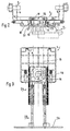
- FIG. 2 shows a cross section through the sliding device 5 and the associated guide arrangement 22, and in FIG. 3 the sliding device 5 can be seen in a bird's eye view.
- a controllable geared motor 11 is screwed to a support plate 10 which is fixedly connected to the sorting device 1.
- a driven deflection roller 13 is fastened to the vertically standing drive shaft 12, which passes through the support plate 10 and which, with a deflection roller 14 spaced in the direction of movement of the sliding device 5, forms an endless traction means 15, for example flat or toothed belt, according to arrow F in FIG. 1 drives all round.
- Attached to the traction means 15 is an outwardly projecting driver 16, which is connected to the traction means 15 by a fastening part 17 and projects with a driver part 18 into a cavity 19 provided in the sliding device 5 and formed by connected wall sections.
- the wall sections of the cavity 19 cooperate with the driver part 18 of the driver 16 fastened to the traction means 15 in a supporting and controlling manner, so that when the end of the conveyor is reached, the pushing device 5 on the transfer path of the collecting container 4 determined by the distance of the deflecting rollers 13, 14 from the starting position reverses its direction of movement in the collection point 2.
- a guide arrangement 22 formed from a guide groove 20 and a guide bar 21 is provided on both sides of the rotating traction means 15, the guide groove 20 in a profile bar 23 fastened to the support plate 10 and that in the guide groove 20 moving guide bar 24 are arranged on the slide device 5.
- the flat-shaped sliding device 5 consists of a wear-resistant material that promotes dimensional stability, for example plastic.
- the drive device 8 formed from the geared motor 11, deflection rollers 13, 14, traction means 15 and driver 16 is arranged below the sliding device 5, so that a compact and low design can be achieved.
- the sliding device 5, in turn, can be seen to have multiple ribs due to its flat design.
- the sliding device 5 is made of several parts for manufacturing reasons.
- a one-piece shape, as illustrated in FIG. 1, cannot be produced to size in an injection molding process.
- a multi-part embodiment as can be seen in FIG. 3 by the displaceable extension 25, allows the length of the sliding device 5 to be adapted to different container dimensions, in particular the container length.
- the tabular rectangular shape of the sliding device 5 is designed on its front face for ejecting the full collection containers 4 ′ from the collection point 2 and on the underside, set back from the front face, has the cavity 19 for the driver part 18 on the traction element 15 around the deflection rollers 13 , 14 current driver 16 on. 3 shows an alternative form of the cavity 19 and the different positions of the driver part 18 in the cavity 19 with the driver 16 rotating. Following the cavity 19, the sliding device 5 is formed by an attachable extension 25, which is required for placing an empty collecting container 4. The complete length of the sliding device 5 can be seen in FIG.
- the double cantilever-like extension 25 can also be seen, which can be moved between the rollers 7 of the preparation section 6 and has a stop 26 at the rear end for taking the overlying collecting container 4.
- the length of the transfer path is determined by the distance between the deflection rollers 13, 14 or their diameter and the design of the cavity 18.
- the driven deflection roller 13 of the traction means 15 of a pushing device 5 connected to a geared motor 11 is located between the ready position of a collecting container 4 standing on the rollers 7 and the collecting point 2, at which the collecting containers 4 are loaded with products.
- the rear region of the sliding device in the transfer direction extends through the extension 25 into the ready position of an empty collecting container 4.
- a cavity 19 for the driver part 18 of the Driver 16 can be slot-shaped, for example.
- Fig. 4 shows a transverse to the direction of movement of the sliding device 5 extending guide slot 27 as a cavity 19 and the guide roller 14 of the traction device 15.
- the driver 16 fastened to the traction means 15 drives the pushing device 5 through the driver part 18 which dips into the transversely arranged guide slot 27.
- the driver part 18 moves on the quarter-circle arc of the deflecting roller within the guide slot 27 by half the way of its movement to the reversal point on the deflecting roller and leaves this location by another half way in the same direction.
- the sliding device 5 is increasingly accelerated in the opposite direction, the driver part 18 having been in contact with the deflecting roller 14 on the opposite wall since the point of reversal (see FIG. 4.2). The same process is repeated in the opposite direction on the opposite pulley.
- a control system ensures that the sliding device 5 stops or is stopped at the starting position until the next change of a collecting container 4.
- a guide slot 27 makes an exact stop of the sliding device 5, which with a free running resp. uncontrolled, inexpensive motor is connected to the drive, not easy.
- a cavity 19 shown in FIG. 3 can be used instead of a guide slot 27.
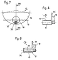
- Such a cavity 19 is shown in FIGS. 5, 5.1 and 5.2.
- Driver part 18 forms.
- Fig. 5.2 shows the situation in which the driver 16 or.
- Driver part 18 moves after the reversal point on a guide track 31 and then reaches the diametrically opposite wall section 28 '.
- the pushing device 5 On the angular section ⁇ of the guideway 31 - which is less than 90 ° due to the necessary guide play - the pushing device 5 is held in a locked position by the driver part 18 and remains in this position until the driver part 18 hits the wall section 28 'or stand in collection point 2.
- the driver 16 consists of a driver part 18 which projects into the cavity 19 of the sliding device 5 and a fastening part 17 connected to the rotating traction means 15, flat or toothed belt, according to FIGS. 6 to 8.
- Fig. 7 shows the type of attachment of the driver 16 to the traction means 15 by a loop 33 formed from the traction means 15 in a cylindrical chamber 34 of the fastening part 17 a threaded bolt 35 respectively fastened in the latter.
- the driver 16 has between the driver part 18 and the fastening part 17 a support member 36 which is useful for maintaining and guiding the traction means 15, in particular on the straight sections where the support member 36 is guided along a bar (not visible).
- this could be equipped with a filling quantity measuring device which is connected to a control for triggering a signal when a collection container 4, 4' is due to be changed.
Landscapes
- Engineering & Computer Science (AREA)
- Mechanical Engineering (AREA)
- Special Conveying (AREA)
- Discharge Of Articles From Conveyors (AREA)
- Vending Machines For Individual Products (AREA)
- Control And Other Processes For Unpacking Of Materials (AREA)
- Combined Means For Separation Of Solids (AREA)
- Separation, Sorting, Adjustment, Or Bending Of Sheets To Be Conveyed (AREA)
- Supplying Of Containers To The Packaging Station (AREA)
- Sorting Of Articles (AREA)
Description
Verläuft der als Schlitz ausgebildete Hohlraum rechtwinklig zur Bewegung der Schiebevorrichtung, dann wird die Geschwindigkeit der Schiebevorrichtung beim Einlaufen des Mitnehmers in den durch die Umlenkrolle gebildeten gebogenen Bahnabschnitt zusehend verzögert und an dem Wendepunkt des Abschnittes wieder zunehmend beschleunigt, bis er die parallelen Abschnitte des Zugmittels erreicht.
Zur laufenden Aenderung der Bewegung der Schiebevorrichtung des Verzögerungs- bzw. Beschleunigungsendes an der Ueberführungsstrecke könnte der Führungsschlitz auch kurvenförmig ausgebildet sein, zumal beim Ausstossen gefüllter Behälter aus der Sammelstelle ein schädliches Aufprallen der Vorderkante der Schiebervorrichtung am Sammelbehälter vermieden werden sollte.
Bei einem quer verlaufenden geraden Führungsschlitz ist es aufgrund des Auslaufs eines Motors allerdings nur mit entsprechenden zusätzlichen technischen Mitteln (Positionier- oder Servoantrieb) möglich, die Schiebevorrichtung in einer bestimmten Position anzuhalten.
Der Hohlraum besteht geometrisch betrachtet aus zwei sich diametral an einer quer zur Bewegungsrichtung der Schiebevorrichtung verlaufenden Achse gegenüberliegenden gleich grossen geometrischen Flächen, die aus einem Quadrat und einem daran anschliessenden Viertelkreis gebildet sind und einem etwa 45° schräggestellten Auge gleichen, dessen Pupille durch ein zentraler Führungszapfen ausgebildet ist, der im Viertelkreisbereich mit der Wand des Hohlraumes eine Führungsbahn begrenzt.
- Fig. 1
- eine Draufsicht einer auszugsweise dargestellten Sortiereinrichtung zum selektiven Sammeln von flachen Produkten,
- Fig. 2
- einen auszugsweisen Querschnitt durch die Schiebevorrichtung einer Sortiereinrichtung nach der Linie II - II in Fig. 1,
- Fig. 3
- eine Schiebevorrichtung für eine Sortiereinrichtung gemäss Fig. 1,
- Fig. 4,
- 4.1 und 4.2 den schematisch dargestellten Verlauf des Mitnehmers in einem Führungsschlitz,
- Fig. 5,
- 5.1 und 5.2 eine alternative Ausbildung des Hohlraumes und den Verlauf des Mitnehmers,
- Fig. 6
- die Ausbildung eines Mitnehmers in Draufsicht,
- Fig. 7
- den Mitnehmer gemäss Fig. 6 in einer Seitenansicht und
- Fig. 8
- einen Schnitt durch den Mitnehmer gemäss Linie VIII - VIII in Fig. 7.
Die Pfeilrichtung der strichpunktierten Linie für den Förderer 3 gibt dessen Transportrichtung an. Der dargestellte Sammelbereich weist einen Bereitstellungsabschnitt 6 für die den Sammelstellen 2 zugeordneten Sammelbehälter 4 auf, die auch manuell auf die Schiebevorrichtung 5 gestellt werden könnten.
Der Bereitstellungsabschnitt 6 an der Seite der Sammelstellen 2 ist durch antreibbare Rollen 7 ausgebildet, die ein lückenloses Bereitstellen leerer Sammelbehälter 4 entlang des Sammelbereichs gewährleisten können, d.h. dass jede Sammelstelle 2 jeweils über einen leeren Sammelbehälter 4 verfügen kann. Die Förderrichtung des Bereitstellungsabschnittes 6 kann gleichoder gegensinnig zur Förderrichtung des Förderers 3 sein. In der Position A befindet sich die Schiebevorrichtung 5, die später detaillierter beschrieben ist, in ihrer Ausgangslage, in der die Sammelstelle 2 durch einen Sammelbehälter 4 unterhalb des Förderers 3 belegt ist.
In der Ausgangsstelle der Schiebevorrichtung 5 bildet diese im Aufnahmebereich des Sammelbehälters 4 etwa eine Ebene mit der Oberseite der Rollen 7.
Die Sammelstellen 2 sind als Abstellplätze für die mit Produkten zu beschickenden Sammelbehälter 4 ausgebildet, wobei die den leeren Sammelbehälter 4 in die Sammelstelle 2 versetzende Schiebevorrichtung 5 auf dem Rückweg in die Ausgangsposition unter dem Sammelbehälter 4, der mit seiner in Zuführrichtung rückwärtigen Wand an einer eingeschwenkten Rückhaltevorrichtung 9 ansteht, hervorgezogen wird.
Die Rückhalteposition entspricht der Sammelposition des Sammelbehälters 4.
An einer mit der Sortiereinrichtung 1 gestellfest verbundenen Tragplatte 10 ist ein steuerbarer Getriebemotor 11 angeschraubt. An der senkrecht stehenden Antriebswelle 12, die die Tragplatte 10 durchsetzt, ist eine angetriebene Umlenkrolle 13 befestigt, die mit einer in Bewegungsrichtung der Schiebevorrichtung 5 beabstandeten Umlenkrolle 14 ein endloses Zugmittel 15, bspw. Flach- oder Zahnriemen, gemäss Pfeil F in Fig. 1 umlaufend antreibt. An dem Zugmittel 15 ist ein nach aussen abstehender Mitnehmer 16 befestigt, der durch einen Befestigungsteil 17 mit dem Zugmittel 15 verbunden ist und mit einem Mitnehmerteil 18 in einen in der Schiebevorrichtung 5 vorgesehenen, durch verbundene Wandabschnitte gebildeten Hohlraum 19 ragt.
Die Wandabschnitte des Hohlraumes 19 wirken mit dem Mitnehmerteil 18 des an dem Zugmittel 15 befestigten Mitnehmers 16 fördernd und steuernd zusammen, so dass die Schiebevorrichtung 5 bei Erreichen des Förderendes an der durch den Abstand der Umlenkrollen 13, 14 bestimmten Ueberführungsstrecke der Sammelbehälter 4 von der Ausgangslage in die Sammelstelle 2 ihre Bewegungsrichtung reversiert.
Zur Bewegung der Schiebevorrichtung 5 von der Ausgangslage in die Sammelstelle 2 und zurück ist eine aus Führungsnute 20 und Führungsleiste 21 gebildete Führungsanordnung 22 beidseits des umlaufenden Zugmittels 15 vorgesehen, wobei die Führungsnute 20 in einer an der Tragplatte 10 befestigten Profilleiste 23 und die in der Führungsnute 20 bewegte Führungsleiste 24 an der Schiebervorrichtung 5 angeordnet sind.
Die aus Getriebemotor 11, Umlenkrollen 13, 14, Zugmittel 15 und Mitnehmer 16 gebildete Antriebsvorrichtung 8 ist unterhalb der Schiebevorrichtung 5 angeordnet, sodass eine kompakte und niedrige Bauweise entstehen kann.
Die Schiebevorrichtung 5 wiederum, ist aufgrund ihrer flachen Ausbildung ersichtlich mehrfach verrippt.
In der in Fig. 3 dargestellten Ausführungsform ist die Schiebevorrichtung 5 aus Fabrikationsgründen mehrteilig ausgebildet. Eine einstückige Form, wie in Fig. 1 veranschaulicht, lässt sich in einem Spritzgiessverfahren nicht massgenau herstellen. Ueberdies gestattet eine mehrteilige Ausführungsform, wie in Fig. 3 durch die verschiebbare Verlängerung 25 ersichtlich, eine Anpassung der Länge der Schiebevorrichtung 5 an unterschiedliche Behältermasse, insbesondere die Behälterlänge. Die tafelförmige Rechteckform der Schiebevorrichtung 5 ist an ihrer vorderen Stirnseite zum Ausstossen der vollen Sammelbehälter 4' aus der Sammelstelle 2 ausgebildet und weist an der Unterseite von der vorderen Stirnseite zurückversetzt, den Hohlraum 19 für den Mitnehmerteil 18 des an dem Zugmittel 15 um die Umlenkrollen 13, 14 laufenden Mitnehmers 16 auf.
Fig. 3 zeigt eine alternative Form des Hohlraumes 19 und die verschiedenen Lagen des Mitnehmerteils 18 im Hohlraum 19 bei umlaufendem Mitnehmer 16.
Im Anschluss an den Hohlraum 19 ist die Schiebevorrichtung 5 durch eine aufsteckbare Verlängerung 25 ausgebildet, die zum Aufsetzen eines leeren Sammelbehälters 4 erforderlich ist. Die vollständige Erstreckungslänge der Schiebevorrichtung 5 ist der Fig. 1 entnehmbar, in der auch die zweifach auslegerartige Verlängerung 25 ersichtlich ist, die zwischen die Rollen 7 des Bereitstellungsabschnittes 6 verfahrbar ist und am hinteren Ende einen Anschlag 26 zur Mitnahme des aufliegenden Sammelbehälters 4 aufweist.
Die Länge der Ueberführungsstrecke wird durch den Abstand zwischen den Umlenkrollen 13, 14 bzw. deren Durchmesser und der Ausführung des Hohlraumes 18 bestimmt.
Die mit einem Getriebemotor 11 verbundene angetriebene Umlenkrolle 13 des Zugmittels 15 einer Schiebevorrichtung 5 befindet sich jeweils zwischen der Bereitstellungsposition eines auf den Rollen 7 stehenden Sammelbehälters 4 und der Sammelstelle 2, an der die Sammelbehälter 4 mit Produkten beschickt werden.
In der Ausgangsstellung eines Sammelbehälters 4, dargestellt unter Position A, reicht der in Ueberführungsrichtung hintere Bereich der Schiebevorrichtung durch die Verlängerung 25 in die Bereitstellungsposition eines leeren Sammelbehälters 4.
An der gegenüberliegenden Umlenkrolle wiederholt sich der gleiche Vorgang in entgegengesetzter Richtung. Eine Steuerung sorgt dafür, dass die Schiebevorrichtung 5 an der Ausgangsposition bis zum nächsten Wechsel eines Sammelbehälters 4 stillsteht bzw. angehalten wird. Ein Führungsschlitz 27 macht ein genaues Anhalten der Schiebevorrichtung 5, die mit einem freilaufenden resp. ungesteuerten, kostengüstigen Motor antriebsverbunden ist, nicht einfach.
Auf dem Winkelabschnitt α der Führungsbahn 31 -der aufgrund des notwendigen Führungsspiels weniger als 90° beträgt- wird die Schiebevorrichtung 5 durch den Mitnehmerteil 18 in einer arretierten Lage gehalten und bleibt bis zum Auflaufen des Mitnehmerteils 18 an dem Wandabschnitt 28' in dieser Lage bzw. in der Sammelstelle 2 stehen. Dies ergibt für die Umlenkrolle 14 vom Umkehrpunkt bis zum Wandabschnitt 28' eine Drehbewegung von etwa 135°, die als Auslaufspiel des Getriebemotors 11 benutzt werden kann, wobei das Auslaufspiel insbesondere für den längeren Aufenthalt der Schiebevorrichtung 5 in der Ausgangsstellung, also im Bereitstellungsabschnitt 6 der Sammelbehälter 4 angewendet wird.
Fig. 7 zeigt die Befestigungsart des Mitnehmers 16 am Zugmittel 15, indem eine aus dem Zugmittel 15 gebildete Schlaufe 33 in einer zylindrischen Kammer 34 des Befestigungsteils 17 einen in letzterem befestigten Gewindebolzen 35 resp. Dorn umgibt (siehe auch Fig. 8). Der Mitnehmer 16 weist zwischen Mitnehmerteil 18 und Befestigungsteil 17 ein Abstützorgan 36 auf, das zur Aufrechthaltung und Führung des Zugmittels 15, insbesondere auf den geraden Abschnitten dienlich ist, wo das Abstützorgan 36 entlang einer nicht ersichtlichen Leiste geführt ist.
Bezüglich des Austausches der Sammelbehälter 4, 4' an der Sammelstelle 2, könnte diese mit einer Füllmengemessvorrichtung ausgestattet sein, die mit einer Steuerung zur Auslösung eines Signals beim fälligen Wechsel eines Sammelbehälters 4, 4' verbunden ist.
Claims (18)
- Einrichtung zum Sortieren und selektiven Sammeln von flachen Produkten, wie Versandtaschen, Druckereierzeugnisse oder Werkstücke, die auf dem Förderweg eines umlaufenden Förderers (3), unterhalb diesem an zugewiesenen Sammelstellen (2) in Sammelbehälter (4) abgesetzt werden, wobei die leeren Sammelbehälter (4) auf einer Ueberführungsstrecke zwischen einer seitlichen Bereitstellungsposition (6) und der Sammelstelle (2) durch eine quer zur Bewegungsrichtung des Förderers (3) in einer Führungsanordnung (22) der Ueberführungsstrekke reversierbar angetriebene Schiebevorrichtung (5) versetzbar, und die befüllten Sammelbehälter (4') aus der Sammelstelle (2) ausstossbar sind, dadurch gekennzeichnet, dass die Schiebevorrichtung (5) mit einem an einem um Umlenkrollen (13, 14) umlaufenden Zugmittel (15) befestigten Mitnehmer (16) einer gestellfest angeordneten Antriebsvorrichtung (8) antriebsverbunden ist.
- Einrichtung nach Anspruch 1, dadurch gekennzeichnet, dass der auf parallelen Abschnitten einer Umlaufbahn zweier in Bewegungsrichtung der Schiebevorrichtung (5) beabstandeter Umlenkrollen (13, 14) angetriebene Mitnehmer (16) in einem antriebswirksam verbundene Wände aufweisenden Hohlraum (19) der Schiebevorrichtung (5) quer zur Bewegungsrichtung letzterer hin und her bewegbar angetrieben ist.
- Einrichtung nach Anspruch 2, dadurch gekennzeichnet, dass die Länge der Ueberführungsstrecke wenigstens der wirksamen Länge der parallelen Abschnitte der Umlaufbahn des Mitnehmers (16) entspricht.
- Einrichtung nach einem der Ansprüche 2 und 3, dadurch gekennzeichnet, dass der Hohlraum (19) in seiner Quererstreckung wenigstens die Breite der Umlaufbahn des Mitnehmers (16) im Bereich einer Umlenkrolle (13, 14) aufweist.
- Einrichtung nach einem der Ansprüche 2 bis 4, dadurch gekennzeichnet, dass der Hohlraum (19) zwei sich gegenüberliegende, insbesondere auf den parallelen Abschnitten der Umlaufbahn an dem Mitnehmer (16) anliegende Wandabschnitte (28, 28') aufweist.
- Einrichtung nach einem der Ansprüche 1 bis 5, dadurch gekennzeichnet, dass die Antriebsvorrichtung (8) unterhalb der Schiebevorrichtung (5) angeordnet ist.
- Einrichtung nach einem der Ansprüche 1 bis 6, dadurch gekennzeichnet, dass die Schiebevorrichtung (5) einen dem Sammelbehälter (4) und einen in Bewegungsrichtung folgenden, der Führungsanordnung (22) resp. der Antriebsvorrichtung (8) zugeordneten Bereich aufweist.
- Einrichtung nach Anspruch 7, dadurch gekennzeichnet, dass der Sammelbehälterbereich in Ueberführungsrichtung betrachtet hinter dem der Führungsanordnung (22) resp. der Antriebsvorrichtung (8) zugeordneten Bereich der Schiebevorrichtung (5) angeordnet ist.
- Einrichtung nach einem der Ansprüche 2 bis 8, dadurch gekennzeichnet, dass die mit einem Motor (11) verbundene Umlenkrolle (13) des Zugmittels (15) zwischen der Bereitstellungsposition und der Sammelstelle (2) eines Sammelbehälters (4) vorgesehen ist.
- Einrichtung nach einem der Ansprüche 7 bis 9, dadurch gekennzeichnet, dass der in Ueberführungsrichtung hintere Bereich der Schiebevorrichtung (5) sich in der Ausgangsstellung in die Bereitstellungsposition eines Sammelbehälters (4) erstreckt.
- Einrichtung nach Anspruch 5, dadurch gekennzeichnet, dass die Wandabschnitte (28, 28') des Hohlraumes einen quer zur Bewegungsrichtung der Schiebevorrichtung (5) verlaufenden Führungsschlitz (27) bilden.
- Einrichtung nach Anspruch 5, dadurch gekennzeichnet, dass die zum Bewegen der Schiebevorrichtung (5) dem Mitnehmer (16) zugeordneten, quer zur Bewegungsrichtung der Schiebevorrichtung (5) verlaufenden Wandabschnitte (28, 28') diametral einer zur Bewegungsrichtung der Schiebevorrichtung (5) quer gerichteten Parallelebene sich gegenüberliegend angeordnet und durch jeweils einen die Schiebevorrichtung (5) am Ende der Ueberführungsstrecke in Ruhelage haltenden, kreisbogenförmigen Wandabschnitt (29, 29') verlängert sind, der mit einer zentrisch angeordneten Erhebung (30) eine Führungsbahn (31) des Mitnehmers (16) bildet.
- Einrichtung nach Anspruch 12, dadurch gekennzeichnet, dass der gebogene Wandabschnitt (29, 29') mit einem zur Bewegungsrichtung der Schiebevorrichtung (5) parallelen, eine geschlossene Wand des Hohlraumes (19) bildenden Wandabschnitt verbunden ist.
- Einrichtung nach einem der Ansprüche 1 bis 13, dadurch gekennzeichnet, dass der Mitnehmer (16) einen in den Hohlraum (19) ragenden, vorzugsweise zylindrischen Mitnehmerteil (18) und einen mit dem umlaufenden Zugmittel (15) verbundenen Befestigungsteil (17) aufweist, wobei das Zugmittel (15) zumindest annähernd in der Achse des Mitnehmerteils (18) verläuft.
- Einrichtung nach Anspruch 14, dadurch gekennzeichnet, dass das Zugmittel (15) durch Bildung einer von einem Dorn (35) durchsetzten Schlaufe (33) mit dem Befestigungsteil (17) des Mitnehmers (16) verbunden ist.
- Einrichtung nach Anspruch 15, dadurch gekennzeichnet, dass die Schlaufe (33) des Zugmittels (15) in einem Ringspalt in dem Befestigungsteil (17) des Mitnehmers (16) angeordnet ist.
- Einrichtung nach einem der Ansprüche 14 bis 16, dadurch gekennzeichnet, dass der Mitnehmer (16) zwischen Mitnehmerteil (18) und Befestigungsteil (17) ein Abstützorgan (36) aufweist.
- Einrichtung nach einem der Ansprüche 1 bis 17, dadurch gekennzeichnet, dass die wirksame Länge der Schiebevorrichtung (5) in Bewegungsrichtung veränderbar ausgebildet ist.
Priority Applications (10)
| Application Number | Priority Date | Filing Date | Title |
|---|---|---|---|
| DE59905552T DE59905552D1 (de) | 1999-03-22 | 1999-03-22 | Einrichtung zum Sortieren und selektiven Sammeln von flachen Produkten |
| EP99810251A EP1038819B1 (de) | 1999-03-22 | 1999-03-22 | Einrichtung zum Sortieren und selektiven Sammeln von flachen Produkten |
| AT99810251T ATE240253T1 (de) | 1999-03-22 | 1999-03-22 | Einrichtung zum sortieren und selektiven sammeln von flachen produkten |
| AU19464/00A AU762389B2 (en) | 1999-03-22 | 2000-02-24 | Device to sort and selectively collect flat products |
| CA002301431A CA2301431A1 (en) | 1999-03-22 | 2000-03-16 | Device for sorting and selectively collecting flat products |
| US09/528,312 US6431369B1 (en) | 1999-03-22 | 2000-03-17 | Device for sorting and selectively collecting flat products |
| PL00339109A PL339109A1 (en) | 1999-03-22 | 2000-03-20 | Apparatus for sorting and selectively collecting flat objects |
| JP2000078700A JP2000281020A (ja) | 1999-03-22 | 2000-03-21 | 平らな製品を区分けおよび選択収集する装置 |
| NO20001462A NO314394B1 (no) | 1999-03-22 | 2000-03-21 | Innretning for sortering og selektiv samling av flate produkter |
| CN00104701.9A CN1267628A (zh) | 1999-03-22 | 2000-03-22 | 分类和有选择地收集扁平物品的装置 |
Applications Claiming Priority (1)
| Application Number | Priority Date | Filing Date | Title |
|---|---|---|---|
| EP99810251A EP1038819B1 (de) | 1999-03-22 | 1999-03-22 | Einrichtung zum Sortieren und selektiven Sammeln von flachen Produkten |
Publications (2)
| Publication Number | Publication Date |
|---|---|
| EP1038819A1 EP1038819A1 (de) | 2000-09-27 |
| EP1038819B1 true EP1038819B1 (de) | 2003-05-14 |
Family
ID=8242737
Family Applications (1)
| Application Number | Title | Priority Date | Filing Date |
|---|---|---|---|
| EP99810251A Expired - Lifetime EP1038819B1 (de) | 1999-03-22 | 1999-03-22 | Einrichtung zum Sortieren und selektiven Sammeln von flachen Produkten |
Country Status (10)
| Country | Link |
|---|---|
| US (1) | US6431369B1 (de) |
| EP (1) | EP1038819B1 (de) |
| JP (1) | JP2000281020A (de) |
| CN (1) | CN1267628A (de) |
| AT (1) | ATE240253T1 (de) |
| AU (1) | AU762389B2 (de) |
| CA (1) | CA2301431A1 (de) |
| DE (1) | DE59905552D1 (de) |
| NO (1) | NO314394B1 (de) |
| PL (1) | PL339109A1 (de) |
Families Citing this family (18)
| Publication number | Priority date | Publication date | Assignee | Title |
|---|---|---|---|---|
| WO2000053344A1 (en) * | 1999-03-09 | 2000-09-14 | Atecs Mannesmann Ag | Automatic tray-handling system for sorter |
| EP1213239A3 (de) * | 2000-10-16 | 2002-07-03 | Siemens Schweiz AG | Vorrichtung zum Fördern und Sortieren von Stückgütern |
| EP1243349A1 (de) * | 2001-03-24 | 2002-09-25 | Siemens Schweiz AG | Verfahren und Vorrichtung zur Befüllung und zum automatischen Abtransport von Sortiergutaufnahmebehältern |
| DE10305847B3 (de) * | 2003-02-12 | 2004-08-19 | Siemens Ag | Sortiereinrichtung für flache Sendungen |
| US20060000752A1 (en) * | 2003-03-28 | 2006-01-05 | Northrop Grumman Corporation | Stack correction system and method |
| US20050077217A1 (en) * | 2003-03-28 | 2005-04-14 | Hillerich Thomas A. | Carrier for mail and/or the like thin objects |
| US7195236B2 (en) * | 2003-03-28 | 2007-03-27 | Northrop Grumman Corporation | Automated induction systems and methods for mail and/or other objects |
| US20040245714A1 (en) * | 2003-05-13 | 2004-12-09 | Ryan Patrick J. | Enhanced object-feeder pre-processing system |
| US20060099065A1 (en) * | 2004-08-27 | 2006-05-11 | Northrop Grumman Corporation | Preparation operator flex-station for carrier preparation |
| US7467792B2 (en) * | 2004-09-24 | 2008-12-23 | Northrop Grumman Corporation | Anti-toppling device for mail with retractable protrusion |
| SE529659C2 (sv) * | 2005-12-02 | 2007-10-16 | Straalfors Ab | Förfarande och anordning vid försändelsekontroll |
| ITUD20070196A1 (it) | 2007-10-24 | 2009-04-25 | Baccini S P A | Magazzino automatico e procedimento per lo stoccaggio di piastre di circuiti elettronici |
| US7766171B2 (en) * | 2008-02-28 | 2010-08-03 | Northrop Grumman Systems Corporation | Rigid storage tray for flat and letter mail |
| CN102514926A (zh) * | 2011-12-02 | 2012-06-27 | 上海电机学院 | 供料机 |
| CN104665123B (zh) * | 2015-03-06 | 2017-02-08 | 南通乐士机械有限公司 | 一种制鞋机的送料装置 |
| CN105057219B (zh) * | 2015-07-22 | 2018-11-27 | 杭州亚美利嘉科技有限公司 | 包裹分捡系统及方法 |
| CN108996091B (zh) * | 2018-06-15 | 2023-07-18 | 深圳前海久禾科技发展有限公司 | 一种料盘推拉机构及料盘推拉方法 |
| CN114273262B (zh) * | 2021-12-14 | 2022-11-08 | 江苏永鼎光电子技术有限公司 | 一种滤波片加工用全自动摆盘机 |
Family Cites Families (9)
| Publication number | Priority date | Publication date | Assignee | Title |
|---|---|---|---|---|
| JPH0734686Y2 (ja) * | 1987-06-16 | 1995-08-09 | シチズン時計株式会社 | 歯付ベルト |
| US4895242A (en) * | 1987-10-26 | 1990-01-23 | G B Instruments, Inc. | Direct transfer sorting system |
| IT1236734B (it) * | 1989-10-24 | 1993-03-31 | Photo Eng Int | Linea di smistamento di buste di lavorazione, particolarmente per laboratori fotografici |
| JP2597280Y2 (ja) * | 1992-12-16 | 1999-07-05 | シチズン時計株式会社 | プリンタ装置 |
| DK0638501T3 (da) | 1993-08-10 | 1997-06-09 | Grapha Holding Ag | Transportindretning til videretransport af enkeltvis flade produkter |
| US5419457A (en) * | 1993-08-30 | 1995-05-30 | Electrocom Gard Ltd. | System for sorting mail pieces on multiple levels and a method for performing the same |
| JP3475645B2 (ja) * | 1996-03-12 | 2003-12-08 | セイコーエプソン株式会社 | プリンタ |
| EP0899026B1 (de) * | 1997-09-01 | 2002-03-20 | Siemens Aktiengesellschaft | Einrichtung zum Sortieren bzw. zum selektiven Sammeln von mittels einem Förderer einzeln zugeführten flachen Produkten |
| EP0949166A1 (de) | 1998-04-09 | 1999-10-13 | Grapha-Holding Ag | Verfahren für eine lückenlose Aufstellung von einem Bereitstellungsabschnitt hintereinander zugeführten Behältern |
-
1999
- 1999-03-22 EP EP99810251A patent/EP1038819B1/de not_active Expired - Lifetime
- 1999-03-22 DE DE59905552T patent/DE59905552D1/de not_active Expired - Fee Related
- 1999-03-22 AT AT99810251T patent/ATE240253T1/de not_active IP Right Cessation
-
2000
- 2000-02-24 AU AU19464/00A patent/AU762389B2/en not_active Ceased
- 2000-03-16 CA CA002301431A patent/CA2301431A1/en not_active Abandoned
- 2000-03-17 US US09/528,312 patent/US6431369B1/en not_active Expired - Fee Related
- 2000-03-20 PL PL00339109A patent/PL339109A1/xx not_active IP Right Cessation
- 2000-03-21 JP JP2000078700A patent/JP2000281020A/ja active Pending
- 2000-03-21 NO NO20001462A patent/NO314394B1/no not_active IP Right Cessation
- 2000-03-22 CN CN00104701.9A patent/CN1267628A/zh active Pending
Also Published As
| Publication number | Publication date |
|---|---|
| DE59905552D1 (de) | 2003-06-18 |
| JP2000281020A (ja) | 2000-10-10 |
| NO20001462D0 (no) | 2000-03-21 |
| NO314394B1 (no) | 2003-03-17 |
| AU1946400A (en) | 2000-09-28 |
| CA2301431A1 (en) | 2000-09-22 |
| NO20001462L (no) | 2000-09-25 |
| US6431369B1 (en) | 2002-08-13 |
| CN1267628A (zh) | 2000-09-27 |
| PL339109A1 (en) | 2000-09-25 |
| ATE240253T1 (de) | 2003-05-15 |
| AU762389B2 (en) | 2003-06-26 |
| EP1038819A1 (de) | 2000-09-27 |
Similar Documents
| Publication | Publication Date | Title |
|---|---|---|
| EP1038819B1 (de) | Einrichtung zum Sortieren und selektiven Sammeln von flachen Produkten | |
| DE4090308C5 (de) | Sortierförderer | |
| DE2330669C3 (de) | Antriebseinrichtung für eine Förderanlage mit einer endlosen Fahrspur | |
| EP0930248B1 (de) | Vorrichtung zum Sortieren von Stückgütern | |
| DE60318496T2 (de) | Maschine zur lieferung/ausgabe von länglichen gegenständen wie länglichen behältern | |
| DE10020608A1 (de) | Lager- und/oder Transportvorrichtung für Stückgüter | |
| DE2457858C2 (de) | Vorrichtung zum Ausrichten von Kapseln | |
| EP1123884A1 (de) | Vorrichtung zum Ablenken von Gegenständen, insbesondere Behältern, von einer Bewegungsbahn | |
| AT412397B (de) | Vorrichtung zum ausrichten und/oder sortieren von einzelteilen | |
| DE2530886C3 (de) | Vorrichtung zum Ordnen vereinzelter, in entgegengesetzten Richtungen ungeordnet orientierter Gegenstände | |
| DE2127310C3 (de) | Fördereinrichtung für Flaschen oder ähnliches Fördergut | |
| DE3302106C2 (de) | Vorrichtung zum Ausschleusen von längs einer Förderbahn transportierten Gegenständen, insbesondere Flaschen | |
| EP1882500B1 (de) | Einrichtung zum Werfen von Bällen | |
| EP0501923A1 (de) | Vorrichtung zum Wenden von flachen Objekten wie zum Beispiel von Wertscheinpaketen | |
| DE2615998A1 (de) | Vorrichtung mit sammelkorb zum sammeln von drucksachen in form eines stapels und abgabe des stapels | |
| DE3714108C2 (de) | ||
| DE3909373C2 (de) | ||
| EP0507156B1 (de) | Vorrichtung zum Transportieren von Verschlusskappen in Gefässverschliessmaschinen | |
| EP0423519B1 (de) | Transportbahn zum Weiterleiten von Spinnkannen und Verwendung der Transportbahn | |
| DE2825800A1 (de) | Vorrichtung zum buendeln von im wesentlichen zylindrischen gegenstaenden zu paketen | |
| DE1936371C3 (de) | Vorrichtung zum Abfördern fertiger Stapel von Druckerzeugnissen | |
| DE4342084C2 (de) | Vorrrichtung zum Ausrichten von Gegenständen | |
| DE2620788C2 (de) | Blasformmaschine | |
| AT394703B (de) | Selbstfahrender wagen | |
| DE2108798B2 (de) | Übergabe- und Zentriereinrichtung zu einem Aufzug |
Legal Events
| Date | Code | Title | Description |
|---|---|---|---|
| PUAI | Public reference made under article 153(3) epc to a published international application that has entered the european phase |
Free format text: ORIGINAL CODE: 0009012 |
|
| AK | Designated contracting states |
Kind code of ref document: A1 Designated state(s): AT BE CH DE FR GB IT LI |
|
| AX | Request for extension of the european patent |
Free format text: AL;LT;LV;MK;RO;SI |
|
| RAP1 | Party data changed (applicant data changed or rights of an application transferred) |
Owner name: SIEMENS AKTIENGESELLSCHAFT |
|
| 17P | Request for examination filed |
Effective date: 20010319 |
|
| AKX | Designation fees paid |
Free format text: AT BE CH DE FR GB IT LI |
|
| GRAH | Despatch of communication of intention to grant a patent |
Free format text: ORIGINAL CODE: EPIDOS IGRA |
|
| GRAH | Despatch of communication of intention to grant a patent |
Free format text: ORIGINAL CODE: EPIDOS IGRA |
|
| GRAA | (expected) grant |
Free format text: ORIGINAL CODE: 0009210 |
|
| AK | Designated contracting states |
Designated state(s): AT BE CH DE FR GB IT LI |
|
| REG | Reference to a national code |
Ref country code: GB Ref legal event code: FG4D Free format text: NOT ENGLISH |
|
| REG | Reference to a national code |
Ref country code: CH Ref legal event code: EP |
|
| GBT | Gb: translation of ep patent filed (gb section 77(6)(a)/1977) |
Effective date: 20030515 |
|
| REF | Corresponds to: |
Ref document number: 59905552 Country of ref document: DE Date of ref document: 20030618 Kind code of ref document: P |
|
| ET | Fr: translation filed | ||
| PLBE | No opposition filed within time limit |
Free format text: ORIGINAL CODE: 0009261 |
|
| STAA | Information on the status of an ep patent application or granted ep patent |
Free format text: STATUS: NO OPPOSITION FILED WITHIN TIME LIMIT |
|
| PG25 | Lapsed in a contracting state [announced via postgrant information from national office to epo] |
Ref country code: AT Free format text: LAPSE BECAUSE OF NON-PAYMENT OF DUE FEES Effective date: 20040322 |
|
| PG25 | Lapsed in a contracting state [announced via postgrant information from national office to epo] |
Ref country code: LI Free format text: LAPSE BECAUSE OF NON-PAYMENT OF DUE FEES Effective date: 20040331 Ref country code: CH Free format text: LAPSE BECAUSE OF NON-PAYMENT OF DUE FEES Effective date: 20040331 |
|
| 26N | No opposition filed |
Effective date: 20040217 |
|
| REG | Reference to a national code |
Ref country code: CH Ref legal event code: PL |
|
| PGFP | Annual fee paid to national office [announced via postgrant information from national office to epo] |
Ref country code: IT Payment date: 20060331 Year of fee payment: 8 |
|
| PGFP | Annual fee paid to national office [announced via postgrant information from national office to epo] |
Ref country code: BE Payment date: 20070321 Year of fee payment: 9 |
|
| BERE | Be: lapsed |
Owner name: SIEMENS A.G. Effective date: 20080331 |
|
| PG25 | Lapsed in a contracting state [announced via postgrant information from national office to epo] |
Ref country code: BE Free format text: LAPSE BECAUSE OF NON-PAYMENT OF DUE FEES Effective date: 20080331 |
|
| PGFP | Annual fee paid to national office [announced via postgrant information from national office to epo] |
Ref country code: GB Payment date: 20090312 Year of fee payment: 11 |
|
| PGFP | Annual fee paid to national office [announced via postgrant information from national office to epo] |
Ref country code: DE Payment date: 20090518 Year of fee payment: 11 |
|
| PG25 | Lapsed in a contracting state [announced via postgrant information from national office to epo] |
Ref country code: IT Free format text: LAPSE BECAUSE OF NON-PAYMENT OF DUE FEES Effective date: 20070322 |
|
| PGFP | Annual fee paid to national office [announced via postgrant information from national office to epo] |
Ref country code: FR Payment date: 20090318 Year of fee payment: 11 |
|
| GBPC | Gb: european patent ceased through non-payment of renewal fee |
Effective date: 20100322 |
|
| REG | Reference to a national code |
Ref country code: FR Ref legal event code: ST Effective date: 20101130 |
|
| PG25 | Lapsed in a contracting state [announced via postgrant information from national office to epo] |
Ref country code: FR Free format text: LAPSE BECAUSE OF NON-PAYMENT OF DUE FEES Effective date: 20100331 |
|
| PG25 | Lapsed in a contracting state [announced via postgrant information from national office to epo] |
Ref country code: DE Free format text: LAPSE BECAUSE OF NON-PAYMENT OF DUE FEES Effective date: 20101001 |
|
| PG25 | Lapsed in a contracting state [announced via postgrant information from national office to epo] |
Ref country code: GB Free format text: LAPSE BECAUSE OF NON-PAYMENT OF DUE FEES Effective date: 20100322 |