EP1024073B1 - Structure de carosserie de véhicule à moteur - Google Patents
Structure de carosserie de véhicule à moteur Download PDFInfo
- Publication number
- EP1024073B1 EP1024073B1 EP00101711A EP00101711A EP1024073B1 EP 1024073 B1 EP1024073 B1 EP 1024073B1 EP 00101711 A EP00101711 A EP 00101711A EP 00101711 A EP00101711 A EP 00101711A EP 1024073 B1 EP1024073 B1 EP 1024073B1
- Authority
- EP
- European Patent Office
- Prior art keywords
- section
- center pillar
- body structure
- closed section
- outer panel
- Prior art date
- Legal status (The legal status is an assumption and is not a legal conclusion. Google has not performed a legal analysis and makes no representation as to the accuracy of the status listed.)
- Expired - Lifetime
Links
- 238000000034 method Methods 0.000 claims description 13
- 238000000465 moulding Methods 0.000 claims description 6
- 230000002787 reinforcement Effects 0.000 description 70
- 238000003466 welding Methods 0.000 description 12
- 230000003247 decreasing effect Effects 0.000 description 6
- 239000012530 fluid Substances 0.000 description 3
- 239000000463 material Substances 0.000 description 3
- 229910000797 Ultra-high-strength steel Inorganic materials 0.000 description 2
- 230000000694 effects Effects 0.000 description 2
- 239000011521 glass Substances 0.000 description 2
- 229910000838 Al alloy Inorganic materials 0.000 description 1
- 229910000831 Steel Inorganic materials 0.000 description 1
- 238000005452 bending Methods 0.000 description 1
- 230000001419 dependent effect Effects 0.000 description 1
- 229910052751 metal Inorganic materials 0.000 description 1
- 239000002184 metal Substances 0.000 description 1
- 238000012986 modification Methods 0.000 description 1
- 230000004048 modification Effects 0.000 description 1
- 239000010959 steel Substances 0.000 description 1
Images





Classifications
-
- B—PERFORMING OPERATIONS; TRANSPORTING
- B62—LAND VEHICLES FOR TRAVELLING OTHERWISE THAN ON RAILS
- B62D—MOTOR VEHICLES; TRAILERS
- B62D25/00—Superstructure or monocoque structure sub-units; Parts or details thereof not otherwise provided for
- B62D25/04—Door pillars ; windshield pillars
-
- B—PERFORMING OPERATIONS; TRANSPORTING
- B62—LAND VEHICLES FOR TRAVELLING OTHERWISE THAN ON RAILS
- B62D—MOTOR VEHICLES; TRAILERS
- B62D25/00—Superstructure or monocoque structure sub-units; Parts or details thereof not otherwise provided for
- B62D25/02—Side panels
- B62D25/025—Side sills thereof
Definitions
- the present invention relates to a body structure of a motor vehicle, and in particular to a body structure of a motor vehicle which is provided with a structure manufactured by a tube hydraulic forming method or the like.
- a hollow structure is obtained by supplying high-pressure fluid such as oil into a raw tube and deforming the tube into a predetermined configuration by using a tube hydraulic forming method.
- Japanese Patent Unexamined Publication No. 8-337182 discloses a body structure of a motor vehicle which is provided with two hollow structures formed by a tube hydraulic forming method. In the vehicle body structure, the two hollow structures are mutually connected along a partial area of its longitudinal direction.
- Japanese Patent Unexamined Publication No. 9-150752 discloses a vehicle body frame structure that comprises a plurality of hoop-shaped members.
- the hoop-shaped members are obtained by extruding raw aluminum alloy into hollow members and bending the hollow members. Then, the body frame structure is formed by welding the members to make a doorframe and the like.
- U.S. Patent No. 5,269,585 discloses a motor vehicle body, which is provided with extruded hollow profiles or structures.
- JP 10 218017 A discloses a vehicle body structure including a second reinforcement within the centre pillar.
- the second reinforcement is an extruded sectional reinforcement and the upper portion of the reinforcement is connected with a brace.
- the section configuration of the reinforcement is not uniform.
- DE 195 18 946 A1 discloses a vehicle body structure including a reinforcement member within a front pillar.
- the reinforcement member is made out of an extruded hollow sectional light metal member with a uniform section.
- US 4,911,553 discloses a vehicle body structure including a door sill between an "A" pillar and a "B" pillar.
- the door sill is provided with a steel sill tube which is mounted to the door sill by a support member, and the front end of the tube is connected to the A pillar by an inner hinge member and the rear end of the tube is connected to the B pillar by a brace assembly and a L-shaped brace.
- US 4,355,843 discloses a vehicle body structure including a metallic pipe within the space of the front pillar.
- the hollow structure can be made from materials such as ultra-high-strength steel.
- the ultra-high-strength steel has greater tensile strength than material of the conventional structure formed by press molding.
- the hollow structure has greater proof stress and therefore has great strength, the weight of the vehicle body can be decreased. Accordingly, as mentioned above, many vehicle body structures provided with hollow structures formed by the tube hydraulic forming method have been proposed.
- a reference numeral 1 designates a side body structure of a motor vehicle which is provided with a roof rail section 2, a center pillar section 4 and a side sill section 6.
- the vehicle side body structure 1 comprises a side frame outer panel 8, which is an outer panel structure forming an outer section of the vehicle side body structure, and an inner closed section structure 10.
- the inner closed section structure 10 is disposed along the side frame outer panel 8 in a passenger compartment side and forms a part of an inner section of the vehicle side body structure 1.
- the vehicle side body structure 1 further comprises a plurality of inner bands 12 which are used to attach the inner closed section structure 10 to the side frame outer panel 8.
- the side frame outer panel 8 forming the outer panel structure is manufactured by press molding.
- Front doors 7 and rear doors 9 are respectively attached to the side frame out panel 8 of the vehicle side body structure 1.
- the inner closed section structure 10 is composed of a roof rail reinforcement 22, a center pillar reinforcement 24 and a side sill reinforcement 26.
- the sectional configurations of the inner closed section structure 10 change in accordance with changes in the inner side configurations of the roof rail section 2, the center pillar section 4 and the side sill section 6 of the side frame outer panel 8.
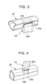
- an upper end 24a of the center pillar reinforcement 24 is inserted into an opening 22a of the roof rail reinforcement 22 and is connected with a connection portion 22b of the roof rail reinforcement 22 by welding or the like.
- the upper end 24a of the center pillar reinforcement 24 is connected with the roof rail reinforcement 22.
- a lower end 24b of the center pillar reinforcement 24 is inserted into an opening 26a of the side sill reinforcement 26 and is connected with a connection portion 26b of the side sill reinforcement 26 by welding or the like.
- the lower end 24b of the center pillar reinforcement 24 is connected with the side sill reinforcement 26.
- the inner closed section structure 10 is formed in the following manner. First, the roof rail reinforcement 22, the center pillar reinforcement 24 and the side sill reinforcement 26 are respectively manufactured by supplying high-pressure fluid such as oil into raw tubes and then deforming the tubes into predetermined configurations under predetermined conditions of the tube hydraulic forming method. Thereafter, as mentioned above, the upper end 24a of the center pillar reinforcement 24 is connected with the roof rail reinforcement 22, and the lower end 24b of the center pillar reinforcement 24 is connected with the side sill reinforcement 26. As a result, the integrally formed inner closed section structure 10 is obtained.
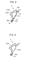
- a roof rail outer 28 which is a part of the side frame outer panel 28, is disposed at an outer side.
- the roof rail reinforcement 22 of the inner closed section structure 10 is disposed at the passenger compartment side of the roof rail outer 28, and the inner band 12 is disposed at the passenger compartment side of the roof rail reinforcement 22.
- a flange 28a of the roof rail outer 28 and a flange 12a of the inner band 12 are mutually connected.
- a part 22c of the surface of the roof rail reinforcement 22 located at an inner side thereof is connected with the inner band 12 by spot welding.
- a seal member 36 is attached to the flanges 12a and 28a to contact the door 9 so that an opening for the door 9 is sealed.
- the roof rail outer 28 which is a part of the side frame outer panel 8, is disposed at an outer side.
- the roof rail reinforcement 22 of the inner closed section structure 10 is disposed at the passenger compartment side of the roof rail outer 28.
- the roof rail outer 28 is provided with the flange 28a to which the seal member 36 is attached. The seal member 36 contacts the door 9 so that the opening for the door 9 is sealed.
- the vehicle side body structure 1 does not need to be provided with an inner section or a roof rail inner of the side body structure, which components need to be provided for the conventional side body structure, since the inner closed section structure 10 of the first embodiment functions, in the area in which the inner band 12 is not provided, as a part of the inner section or the roof rail inner.
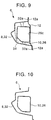
- a center pillar outer 30, which is a part of the side frame outer panel 8 is disposed at an outer side.
- the center pillar reinforcement 24 of the inner closed section structure 10 is disposed at the passenger compartment side of the center pillar outer 30, and the inner band 12 is disposed at the passenger compartment side of the center pillar reinforcement 24.
- a flange 30a of the center pillar outer 30 and a flange 12a of the inner band 12 are mutually connected.
- a part 24c of the surface of the center pillar reinforcement 24 located at an inner side thereof is connected with the inner band 12 by spot welding.
- the seal members 36 are attached to the flanges 12a and 30a to contact the doors 7 and 9 so that the openings for the doors 7 and 9 are sealed.
- the center pillar outer 30, which is a part of the side frame outer panel 8, is disposed at an outer side.
- the center pillar reinforcement 24 of the inner closed section structure 10 is disposed at the passenger compartment side of the center pillar outer 30.
- a flange 30a of the center pillar outer 30 and a flange 12a of the inner band 12 are mutually connected.
- a part 24c of the surface of the center pillar reinforcement 24 located at an inner side thereof is connected with the inner band 12 by spot welding.
- the seal members 36 are attached to the flanges 12a and 30a to contact the doors 7 and 9 so that the openings of the doors 7 and 9 are sealed.
- the center pillar outer 30 is provided with the flanges 30a to which the seal members 36 are respectively attached. The seal members 36 contact the doors 7 and 9 so that the opening for the doors 7 and 9 are sealed.
- the side body structure 1 does not need to be provided with an inner section or a center pillar inner of the side body structure, which components need to be provided for the conventional side body structure.
- the inner closed section structure 10 functions, in the area in which the inner band 12 is not provided, as a part of the inner section or the center pillar inner.
- a side sill outer 32 which is a part of the side frame outer panel 8, is disposed at an outer side.
- the side sill reinforcement 26 of the inner closed section structure 10 is disposed at the passenger compartment side of the side sill outer 32, and the inner band 12 is disposed at the passenger compartment side of the side sill reinforcement 26.
- Flanges 32a of the side sill outer 32 and the flanges 12a of the inner band 12 are mutually connected.
- a part 26c of the surface of the side sill reinforcement 26 located at an inner side thereof is connected with the inner band 12 by spot welding.
- a plurality of flat plate node members 34 are disposed along the side sill 6 between the side sill outer 32 and the side sill reinforcement 26 so as to increase the rigidity of the side sill section 6 and to prevent the distortion of the side sill section 6.
- the side sill outer 32 which is a part of the side frame outer panel 8, is disposed at an outer side.
- the side sill reinforcement 26 of the inner closed section structure 10 is disposed at the passenger compartment side of the side sill outer 32.
- the first embodiment of the present invention has the following advantageous effects.
- the vehicle side body structure 1 does not need to be provided with the inner section, namely the roof rail inner, the center pillar inner and/or the side sill inner, which components need to be provided for the conventional side body structure. This is because the inner closed section structure 10 functions, in the area in which the inner band 12 is not provided, as a part of the inner section.
- the rigidity of the vehicle side body structure 1 is increased.
- the inner closed section structure 10 is made of a single member, as compared with the conventional side body structure, the amount of material and numbers of components are both decreased and thus the weight of the vehicle side body structure 1 is lightened.
- the inner closed section structure 10 is manufactured by the tube hydraulic forming method, the rigidity or stiffness of the side body structure 1 is increased and the weight of the side body structure 1 is decreased, in comparison with the conventional side body structure manufactured by the press molding.
- the sectional configurations of the inner closed section structure 10 change in accordance with changes in the inner side configurations of the roof rail section 2, the center pillar section 4 and the side sill section 6 of the side frame outer panel 8, the number of the components can be decreased.
- the outer panel structure 8 forming the side frame outer panel 8 is disposed at the outer side of the inner closed section structure 10, the flanges of the side frame outer panel 8 can be effectively utilized as the connection portions with the seal portions and the glasses.
- a body structure 40 of a motor vehicle comprises a roof rail section 2, a center pillar section 4 and a side sill section 6.
- the vehicle body structure 1 further comprises a roof section 42 and a floor section 44.
- the vehicle body structure 40 is provided with an outer panel structure 50 (only one side thereof is shown in Figure 11) forming an outer section of the body structure 40.
- the outer panel structure 50 is composed of a side frame outer panel 8, a roof rail outer panel 52 and a floor outer panel 54. These panels 8, 52 and 54 are connected to each other by flanges to form an annular structure.
- the vehicle body structure 40 is further provided with an inner closed section structure 56 which is composed of a roof reinforcement 58, a roof rail reinforcement 60, a center pillar reinforcement 62, a side sill reinforcement 64 and a floor cross member 66. These reinforcements 58, 60, 62 and 64 and the member 66 are connected to each other by welding or the like to form an integral structure.
- the vehicle body structure 40 is further provided with a roof rail inner 68, a center pillar inner 70 and a side sill inner 72 but is not provided with a roof rail inner panel and a floor inner panel.
- the side frame outer panel 8, the roof rail outer panel 52 and the floor outer panel 54 of the outer panel structure 50 are respectively manufactured by press molding like conventional outer panels.
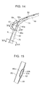
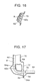
- the outer panels 8, 52 and 54 of the outer panel structure 50 are connected to each other through flanges 8a, 52a and 54a by welding or the like to form an integral structure (see Figures 14 and 17).
- the roof reinforcement 58, the roof rail reinforcement 60, the center pillar reinforcement 62, the side sill reinforcement 64 and the floor cross member 66 of the inner closed section structure 56 are respectively manufactured by the above-mentioned tube hydraulic forming method. Namely, at first, high-pressure fluid such as oil is supplied into the reinforcements 58, 60, 62 and 64 and the member 66 under predetermined conditions of the tube hydraulic forming method. Thereafter, the reinforcements 58, 60, 62 and 64 and the member 66 are respectively deformed into predetermined configurations and then connected each other. As a result, the integral inner closed section structure 56 is obtained.
- the sectional configurations of the inner closed section structure 56 change in accordance with changes in the inner side configurations of the roof rail section 2, the center pillar section 4 and the side sill section 6 of the outer panel structure 50.
- both ends of the roof reinforcement 58 are respectively connected at connecting portions 74 with upper ends of the center pillar reinforcements 62.
- both ends of the cross member 66 are respectively connected at connecting portions 76 with lower ends of the center pillar reinforcements 62.
- the center pillar reinforcement 62 is disposed at an inner side of the roof rail reinforcement 60 so as to intersect vertically the roof rail reinforcement 60.
- a part 60a of the inner side surface of the roof rail reinforcement 60 is connected by spot welding with a part 62a of the outer side surface of the intersected portion of the center pillar reinforcement 62.
- a part 62b of the inner side surface of the center pillar reinforcement 62 is connected by spot welding with the roof rail inner 68.
- the side sill reinforcement 64 is disposed at an inner side of the lower end of the center pillar reinforcement 62 so as to intersect vertically the center pillar reinforcement 62.
- a part 62b of the inner side surface of the center pillar reinforcement 62 is connected by spot welding with a part 64a of the outer side surface of the intersected portion of the side sill reinforcement 64.
- the center portion of the center pillar reinforcement 62 has a sectional configuration including a wavy form 62c.
- the vehicle body structure 40 is provided with the roof rail inner 68, the center pillar inner 70 and the side sill inner 72 but is not provided with the roof rail inner panel and the floor inner panel.
- the second embodiment is not limited to the above-mentioned structure. Namely, in the second embodiment, the vehicle body structure 40 may not be provided with any one of the above components, namely, the roof rail inner 68, the center pillar inner 70, the side sill inner 72, the roof rail inner panel and the floor inner panel. Further, in the second embodiment, the vehicle body structure 40 may not be provided with predetermined components taken from the components 68, 70, 72, the roof rail inner panel and the floor inner panel.
- the second embodiment of the present invention has the following advantageous effects.
- the inner closed section structure 56 function as the inner section of the vehicle body structure 40. More specifically, the roof reinforcement 58 and the floor cross member 66 of the inner closed section structure 56 respectively function as the roof inner panel in the roof section 42 and the floor inner panel in the floor section 44 of the vehicle body structure 40. As a result, for example, the roof inner panel and the floor inner panel that are required in the conventional body structure are not required in the vehicle body structure 40 of the second embodiment.
- the rigidity of the vehicle body structure 40 is increased. Since the inner closed section structure 56 is an annular structure, the rigidity of the body structure 50 against a load acting from the side direction of the vehicle is greatly increased.
- the inner closed section structure 56 is manufactured by the tube hydraulic forming method, the rigidity of the body structure 40 is increased and the weight of the body structure 40 is decreased in comparison with the conventional body structure manufactured by the press molding.
- the sectional configurations of the inner closed section structure 56 change in accordance with changes in the inner side configurations of the roof rail section 2, the center pillar section 4 and the side sill section 6 of the outer panel structure 50, the number of the components can be decreased.
- the outer panel structure 50 such as the side frame outer panel 8 or the like is disposed at the outer side of the inner closed section structure 56, the flanges of the side frame outer panel 8 or the like forming the outer panel structure 50 can be effectively utilized as the connection portions with the seal portions and the glasses.
Landscapes
- Engineering & Computer Science (AREA)
- Chemical & Material Sciences (AREA)
- Combustion & Propulsion (AREA)
- Transportation (AREA)
- Mechanical Engineering (AREA)
- Body Structure For Vehicles (AREA)
Claims (9)
- Structure de carrosserie pour un véhicule à moteur ayant une section intérieure (10) et une section extérieure (8) comprenant :une structure de panneau extérieur (8) forme la section extérieure de la structure de carrosserie (1), ladite structure de panneau extérieur (8) étant un panneau intégral formant au moins un extérieur de rail de toiture (28), un extérieur de pilier central (30) et un extérieur de seuil latéral (32) et étant fabriquée par moulage à la presse ; etune structure intérieure à section fermée (10) disposée le long de zones de l'extérieur de rail de toiture (28) de l'extérieur de pilier central (30) et de l'extérieur de seuil latéral (32) de la structure de panneau extérieur (8) et attachée à la structure de panneau extérieur (8), ladite structure intérieure à section fermée (10) ayant en section une configuration qui change en accord avec les changements de la configuration latérale intérieure de la structure de panneau extérieur (8), et étant fabriquée par un procédé de formage hydraulique de tubes, ladite structure intérieure à section fermée (10) faisant office de partie de la section intérieure de la structure de carrosserie (1).
- Structure de carrosserie pour un véhicule à moteur selon la revendication 1, dans laquelle ladite structure intérieure à section fermée (10) est supportée par des bandes intérieures (12) qui sont respectivement connectées avec des brides (12a) de l'extérieur de rail de toiture (28) et de l'extérieur de pilier central (30).
- Structure de carrosserie pour un véhicule à moteur selon la revendication 1, dans laquelle ladite structure intérieure à section fermée (10) est supportée par des bandes intérieures (12) qui sont respectivement connectées avec des brides (12a) de l'extérieur de pilier central (30) et de l'extérieur de seuil latéral (32).
- Structure de carrosserie pour un véhicule à moteur selon la revendication 1, dans laquelle ladite structure de panneau extérieur (8) est un panneau intégral formant au moins un extérieur de pilier central (30) et un extérieur de toiture (28), et ladite structure intérieure à section fermée (10) est disposée intégralement le long de zones de l'extérieur de pilier central (30) et de l'extérieur de toiture (28) de la structure de panneau extérieur (8).
- Structure de carrosserie pour un véhicule à moteur selon la revendication 1, dans laquelle ladite structure de panneau extérieur (8) est un panneau intégral formant au moins un extérieur de pilier central (30) et un extérieur de plancher (32), et ladite structure intérieure à section fermée (10) est disposée intégralement le long de zones de l'extérieur de pilier central (30) et de l'extérieur de plancher (32) de la structure de panneau extérieur.
- Structure de carrosserie pour un véhicule à moteur selon l'une quelconque des revendications 1 à 5, dans laquelle ladite structure intérieure à section fermée (10) a une section fermée disposée intégralement le long de zones d'une section de pilier central, d'une section de toiture (52), et d'une section de plancher (54) de la structure de panneau extérieur (8).
- Structure de carrosserie pour un véhicule à moteur selon l'une quelconque des revendications 1 à 6, dans laquelle ladite structure intérieure à section fermée (10) a une section fermée disposée intégralement le long de zones d'une section de pilier central, d'une section de toiture (52), d'une section de plancher (54), et d'une section de rail de toiture de la structure de panneau extérieur (8).
- Structure de carrosserie pour un véhicule à moteur selon l'une quelconque des revendications 1 à 7, dans laquelle ladite structure intérieure à section fermée (10) a une section fermée disposée intégralement le long de zones d'une section de pilier central, d'une section de toiture (52), d'une section de plancher (54), et d'un seuil latéral de la structure de panneau extérieur (8).
- Structure de carrosserie pour un véhicule à moteur selon la revendication 2, dans laquelle ledit panneau intégral de la structure de panneau extérieur (8) a une bride (28a) à laquelle sont attachés des moyens d'étanchement (36).
Applications Claiming Priority (2)
| Application Number | Priority Date | Filing Date | Title |
|---|---|---|---|
| JP02310599A JP3500626B2 (ja) | 1999-01-29 | 1999-01-29 | 車両の車体構造 |
| JP2310599 | 1999-01-29 |
Publications (2)
| Publication Number | Publication Date |
|---|---|
| EP1024073A1 EP1024073A1 (fr) | 2000-08-02 |
| EP1024073B1 true EP1024073B1 (fr) | 2003-05-14 |
Family
ID=12101196
Family Applications (1)
| Application Number | Title | Priority Date | Filing Date |
|---|---|---|---|
| EP00101711A Expired - Lifetime EP1024073B1 (fr) | 1999-01-29 | 2000-01-27 | Structure de carosserie de véhicule à moteur |
Country Status (5)
| Country | Link |
|---|---|
| US (1) | US6322135B1 (fr) |
| EP (1) | EP1024073B1 (fr) |
| JP (1) | JP3500626B2 (fr) |
| KR (1) | KR20000053613A (fr) |
| DE (1) | DE60002616T2 (fr) |
Cited By (1)
| Publication number | Priority date | Publication date | Assignee | Title |
|---|---|---|---|---|
| US12319348B2 (en) * | 2022-01-10 | 2025-06-03 | Hyundai Motor Company | Vehicle body structure |
Families Citing this family (56)
| Publication number | Priority date | Publication date | Assignee | Title |
|---|---|---|---|---|
| US6623067B2 (en) * | 1997-10-16 | 2003-09-23 | Magna International Inc. | Door seal interface structure for a motor vehicle space frame |
| JP3428545B2 (ja) * | 2000-01-07 | 2003-07-22 | 本田技研工業株式会社 | 車体補強構造 |
| DE20005471U1 (de) * | 2000-03-23 | 2000-06-21 | Benteler Ag, 33104 Paderborn | Instrumententräger |
| JP4586267B2 (ja) * | 2000-12-20 | 2010-11-24 | マツダ株式会社 | 車両の上部車体構造 |
| US6409256B1 (en) * | 2001-01-23 | 2002-06-25 | Guardian Industries Corp. | Multi-piece applique for vehicle B-pillar |
| DE10117009B4 (de) * | 2001-04-05 | 2005-04-21 | Daimlerchrysler Ag | Tragsäule für einen Karosserierahmen eines Kraftfahrzeugs |
| JP3830401B2 (ja) | 2001-06-04 | 2006-10-04 | 株式会社丸順 | 車体のドア開口部回りの構造 |
| US6619729B2 (en) * | 2001-06-07 | 2003-09-16 | Mazda Motor Corporation | Side body structure of vehicle |
| DE10151684B4 (de) | 2001-10-19 | 2005-10-06 | Daimlerchrysler Ag | Seitenwandbaugruppe für eine Kraftfahrzeugkarosserie |
| JP3969054B2 (ja) * | 2001-10-25 | 2007-08-29 | 三菱自動車エンジニアリング株式会社 | 車両のピラー下部構造 |
| DE10232320A1 (de) * | 2002-07-17 | 2004-02-05 | Bayerische Motoren Werke Ag | Fahrzeugkarosserie mit einer B-Säule |
| FR2847875B1 (fr) * | 2002-12-03 | 2005-09-30 | Renault Sa | Ensemble de carrosserie pour vehicule automobile et vehicule comprenant au moins un tel ensemble |
| US6957845B2 (en) * | 2003-07-31 | 2005-10-25 | Dana Corporation | Space frame cross member with integrated door seal feature |
| JP4151527B2 (ja) * | 2003-09-03 | 2008-09-17 | 日産自動車株式会社 | 車体側面構造 |
| US7253374B2 (en) * | 2003-09-15 | 2007-08-07 | General Motors Corporation | Sheet-to-tube welded structure and method |
| US20060001294A1 (en) * | 2004-07-01 | 2006-01-05 | Balgaard Steven P | Rocker assembly for vehicles |
| JP4465599B2 (ja) * | 2004-09-10 | 2010-05-19 | スズキ株式会社 | センターピラー上部の接合構造 |
| DE102004053917B3 (de) * | 2004-11-05 | 2006-04-13 | Benteler Automobiltechnik Gmbh | Seitenwand eines Kraftfahrzeugs |
| US7213874B2 (en) * | 2005-03-09 | 2007-05-08 | Nissan Technical Center North America, Inc. | Vehicle roof structure |
| US7357448B2 (en) * | 2005-06-06 | 2008-04-15 | Ford Global Technologies, Llc | Unitary hydroformed roof support pillar |
| DE102005040718B4 (de) * | 2005-08-27 | 2012-11-22 | Volkswagen Ag | Trägerstruktur |
| JP4555210B2 (ja) | 2005-11-04 | 2010-09-29 | 本田技研工業株式会社 | 自動車の車体構造 |
| US7293823B2 (en) * | 2005-11-16 | 2007-11-13 | Ford Global Technologies, Llc | Interlocked pillar and roof rail joint |
| JP2007191008A (ja) * | 2006-01-18 | 2007-08-02 | Kobe Steel Ltd | 自動車サイドシル |
| US7677652B2 (en) * | 2006-03-29 | 2010-03-16 | Nissan Technical Center North America, Inc. | Roof inner body structure |
| FR2901229B1 (fr) * | 2006-05-18 | 2008-07-04 | Renault Sas | Liaison entre la traverse de pavillon et le renfort superieur de pied milieu d'un vehicule automobile |
| EP2527233B1 (fr) * | 2007-04-04 | 2014-05-14 | Nippon Steel & Sumitomo Metal Corporation | Élément de renfort d'une carrosserie d'automobile |
| JP4445522B2 (ja) * | 2007-06-20 | 2010-04-07 | 豊田鉄工株式会社 | 車両用センターピラーの補強部材 |
| JP4852017B2 (ja) * | 2007-08-06 | 2012-01-11 | 本田技研工業株式会社 | 車体上部構造 |
| JP5003424B2 (ja) * | 2007-11-19 | 2012-08-15 | トヨタ車体株式会社 | 自動車のルーフ構造 |
| DE102008022641B4 (de) * | 2008-05-08 | 2012-03-22 | Daimler Ag | Kraftwagenkarosserie mit einer Säule und einem Dachrahmenelement |
| DE102008024762A1 (de) * | 2008-05-23 | 2009-12-10 | Daimler Ag | Verbindungsanordnung für eine B-Säule eines Kraftwagens |
| JP5262305B2 (ja) * | 2008-05-30 | 2013-08-14 | 新日鐵住金株式会社 | 補強部材、ピラー及び自動車車体 |
| JP5272623B2 (ja) * | 2008-09-30 | 2013-08-28 | マツダ株式会社 | 自動車車体の製造方法 |
| JP5347410B2 (ja) * | 2008-09-30 | 2013-11-20 | マツダ株式会社 | 自動車車体の製造方法 |
| US8662567B2 (en) * | 2009-02-02 | 2014-03-04 | Vari-Form, Inc. | Vehicle roof support pillar assembly |
| ITBO20090492A1 (it) * | 2009-07-28 | 2011-01-29 | Ferrari Spa | Telaio di un veicolo provvisto di un montante centrale estruso |
| DE102009058976A1 (de) * | 2009-12-18 | 2011-06-22 | Audi Ag, 85057 | Schwellerbaugruppe für eine Fahrzeugkarosserie sowie Verfahren zur Herstellung einer Schwellerbaugruppe |
| JP5063757B2 (ja) * | 2010-08-17 | 2012-10-31 | 本田技研工業株式会社 | 車体側部構造 |
| US8702161B2 (en) * | 2010-12-22 | 2014-04-22 | Tesla Motors, Inc. | System for absorbing and distributing side impact energy utilizing an integrated battery pack and side sill assembly |
| US20120161472A1 (en) | 2010-12-22 | 2012-06-28 | Tesla Motors, Inc. | System for Absorbing and Distributing Side Impact Energy Utilizing an Integrated Battery Pack |
| DE102012004761A1 (de) * | 2012-03-08 | 2013-09-12 | GM Global Technology Operations LLC (n. d. Gesetzen des Staates Delaware) | Verstärkungsteil für einen Dachseitenholm |
| DE102013002306A1 (de) * | 2013-02-06 | 2014-08-07 | GM Global Technology Operations LLC (n. d. Ges. d. Staates Delaware) | Fahrzeugsäule, insbesondere B-Säule eines Kraftfahrzeuges |
| JP6105386B2 (ja) * | 2013-05-21 | 2017-03-29 | 豊田鉄工株式会社 | 車両の側部構造 |
| US9139235B2 (en) | 2013-05-21 | 2015-09-22 | Ford Global Technologies, Llc | Vehicle frame rail and pillar connection |
| KR101491319B1 (ko) * | 2013-09-30 | 2015-02-06 | 현대자동차주식회사 | 자동차 필러용 아우터 패널과 그 제조 방법, 그리고 아우터 패널을 제조하기 위한 압연 장치 |
| US9073586B1 (en) * | 2014-06-27 | 2015-07-07 | Ford Global Technologies, Llc | Transverse sill reinforcement for a truck bed and method of making a sill reinforcement |
| JP2016074382A (ja) * | 2014-10-09 | 2016-05-12 | トヨタ自動車株式会社 | 車両上部構造 |
| US9821852B2 (en) * | 2016-02-03 | 2017-11-21 | Ford Global Technologies Llc | Pressurized air insert for side impacts |
| DE102016001241A1 (de) * | 2016-02-04 | 2017-08-10 | GM Global Technology Operations LLC (n. d. Ges. d. Staates Delaware) | Strukturknoten für eine Kraftfahrzeugkarosserie |
| JP6706432B2 (ja) * | 2016-04-25 | 2020-06-10 | スズキ株式会社 | 車両のルーフサイドメンバ |
| JP6489088B2 (ja) * | 2016-08-26 | 2019-03-27 | トヨタ自動車株式会社 | 車両用骨格構造 |
| JP2020203601A (ja) * | 2019-06-18 | 2020-12-24 | マツダ株式会社 | 車両の上部車体構造 |
| JP7287263B2 (ja) * | 2019-12-19 | 2023-06-06 | マツダ株式会社 | 車両の側部車体構造 |
| MX2022008267A (es) | 2020-01-03 | 2022-08-04 | Tesla Inc | Extraccion selectiva de litio a partir de minerales de arcilla. |
| KR20230067148A (ko) | 2021-11-09 | 2023-05-16 | 현대자동차주식회사 | 차량의 바디 |
Family Cites Families (21)
| Publication number | Priority date | Publication date | Assignee | Title |
|---|---|---|---|---|
| JPS5660686U (fr) * | 1979-10-16 | 1981-05-23 | ||
| JP2550700Y2 (ja) * | 1991-07-19 | 1997-10-15 | マツダ株式会社 | 自動車の側部車体構造 |
| DE3918280A1 (de) | 1989-06-05 | 1990-12-06 | Audi Ag | Kraftfahrzeugkarosserie |
| US4944553A (en) * | 1989-06-30 | 1990-07-31 | Chrysler Corporation | Vehicle reinforcing structure |
| US5352011A (en) * | 1991-11-11 | 1994-10-04 | Mazda Motor Corporation | Body structure of an automotive vehicle |
| US5388885A (en) * | 1993-02-01 | 1995-02-14 | General Motors Corporation | Body structure of a motor vehicle |
| JPH07315247A (ja) * | 1994-05-24 | 1995-12-05 | Honda Motor Co Ltd | 車両の構造部材 |
| JP3335781B2 (ja) * | 1994-08-31 | 2002-10-21 | 富士重工業株式会社 | 車両のセンタピラー部全周閉断面構造 |
| JP3335780B2 (ja) * | 1994-08-31 | 2002-10-21 | 富士重工業株式会社 | 車両のセンタピラー下方部の車体構造 |
| JPH08192238A (ja) | 1995-01-12 | 1996-07-30 | Tube Forming:Kk | フレーム成形方法 |
| DE19519353A1 (de) | 1995-05-26 | 1996-11-28 | Porsche Ag | Träger einer Aufbaustruktur eines Fahrzeuges und Verfahren zu dessen Herstellung |
| JPH0930345A (ja) | 1995-07-18 | 1997-02-04 | Nissan Motor Co Ltd | 車体構造用筒状部材およびその製造方法 |
| DE19531874C1 (de) * | 1995-08-30 | 1996-10-02 | Daimler Benz Ag | Seitenwandbaugruppe für eine Kraftfahrzeugkarosserie |
| JPH09150752A (ja) | 1995-09-29 | 1997-06-10 | Honda Motor Co Ltd | 車体フレームの製造方法 |
| JP3302272B2 (ja) | 1996-11-06 | 2002-07-15 | 本田技研工業株式会社 | 車体フレームの製造方法 |
| JP3473729B2 (ja) | 1996-11-06 | 2003-12-08 | 本田技研工業株式会社 | 車体フレームの製造方法 |
| JPH10138950A (ja) | 1996-11-12 | 1998-05-26 | Nissan Motor Co Ltd | 衝撃吸収部材およびその製造方法 |
| TW556692U (en) * | 1997-01-31 | 2003-10-01 | Mazda Motor | Body structure for vehicle |
| JP3572373B2 (ja) * | 1997-01-31 | 2004-09-29 | 日産自動車株式会社 | センターピラーの補強構造 |
| SE512010C2 (sv) * | 1997-02-12 | 2000-01-10 | Saab Automobile | Fordonskaross |
| DE19708905C2 (de) * | 1997-03-05 | 2002-06-27 | Daimler Chrysler Ag | Verfahren zum Herstellen von Karosserieträgern |
-
1999
- 1999-01-29 JP JP02310599A patent/JP3500626B2/ja not_active Expired - Fee Related
-
2000
- 2000-01-26 KR KR1020000003571A patent/KR20000053613A/ko not_active Withdrawn
- 2000-01-27 EP EP00101711A patent/EP1024073B1/fr not_active Expired - Lifetime
- 2000-01-27 DE DE60002616T patent/DE60002616T2/de not_active Expired - Lifetime
- 2000-01-28 US US09/493,177 patent/US6322135B1/en not_active Expired - Lifetime
Cited By (1)
| Publication number | Priority date | Publication date | Assignee | Title |
|---|---|---|---|---|
| US12319348B2 (en) * | 2022-01-10 | 2025-06-03 | Hyundai Motor Company | Vehicle body structure |
Also Published As
| Publication number | Publication date |
|---|---|
| EP1024073A1 (fr) | 2000-08-02 |
| DE60002616T2 (de) | 2004-02-26 |
| US6322135B1 (en) | 2001-11-27 |
| KR20000053613A (ko) | 2000-08-25 |
| JP2000219154A (ja) | 2000-08-08 |
| JP3500626B2 (ja) | 2004-02-23 |
| DE60002616D1 (de) | 2003-06-18 |
Similar Documents
| Publication | Publication Date | Title |
|---|---|---|
| EP1024073B1 (fr) | Structure de carosserie de véhicule à moteur | |
| EP1024074B1 (fr) | Structure de carosserie d'un véhicule à moteur | |
| US7407222B2 (en) | Vehicle body structure | |
| US8651562B2 (en) | B-pillar reinforcement of a motor vehicle | |
| US6692065B2 (en) | Framing structure around vehicle door opening | |
| EP1216865B1 (fr) | Porte légère pour véhicules à moteur | |
| US6428085B1 (en) | Body structure in floor section of vehicle | |
| US20160200364A1 (en) | Vehicle body structure | |
| CA2691477A1 (fr) | Ensemble de poutrelles de toit de vehicule | |
| US12291089B2 (en) | Vehicle door assembly | |
| US6073993A (en) | Body structure for a motor vehicle | |
| US7585017B2 (en) | One-piece, tubular member with an integrated welded flange and associated method for producing | |
| CN111824266A (zh) | 用于机动车辆的边梁组件 | |
| US20030177702A1 (en) | Door shell for a motor vehicle door, profile frame for a door shell and process for the production of a profile frame for a door shell | |
| EP1199245B1 (fr) | Profil pour carosserie | |
| CZ408299A3 (cs) | Dveřní rám pro osobní automobil | |
| GB2280456A (en) | Reinforcing beam | |
| CN101208236A (zh) | 具有一体的焊接凸缘的一件式管形部件以及相关的制造方法 | |
| US7703207B2 (en) | Blank, chassis component and method for production of said chassis component | |
| JP3590965B2 (ja) | 車両の車体構造 | |
| JPH04238725A (ja) | 自動車ドア用インパクトビーム | |
| CN222892061U (zh) | 侧围总成以及车辆 | |
| CA2439537A1 (fr) | Cadre arriere de toit pour automobiles | |
| CN220549106U (zh) | 侧围组件及车辆 | |
| JPH0986172A (ja) | 自動車用ドアガードバー |
Legal Events
| Date | Code | Title | Description |
|---|---|---|---|
| PUAI | Public reference made under article 153(3) epc to a published international application that has entered the european phase |
Free format text: ORIGINAL CODE: 0009012 |
|
| AK | Designated contracting states |
Kind code of ref document: A1 Designated state(s): DE ES FR GB IT |
|
| AX | Request for extension of the european patent |
Free format text: AL;LT;LV;MK;RO;SI |
|
| 17P | Request for examination filed |
Effective date: 20001116 |
|
| AKX | Designation fees paid |
Free format text: DE ES FR GB IT |
|
| GRAH | Despatch of communication of intention to grant a patent |
Free format text: ORIGINAL CODE: EPIDOS IGRA |
|
| GRAH | Despatch of communication of intention to grant a patent |
Free format text: ORIGINAL CODE: EPIDOS IGRA |
|
| GRAA | (expected) grant |
Free format text: ORIGINAL CODE: 0009210 |
|
| AK | Designated contracting states |
Designated state(s): DE ES FR GB IT |
|
| PG25 | Lapsed in a contracting state [announced via postgrant information from national office to epo] |
Ref country code: IT Free format text: LAPSE BECAUSE OF FAILURE TO SUBMIT A TRANSLATION OF THE DESCRIPTION OR TO PAY THE FEE WITHIN THE PRESCRIBED TIME-LIMIT;WARNING: LAPSES OF ITALIAN PATENTS WITH EFFECTIVE DATE BEFORE 2007 MAY HAVE OCCURRED AT ANY TIME BEFORE 2007. THE CORRECT EFFECTIVE DATE MAY BE DIFFERENT FROM THE ONE RECORDED. Effective date: 20030514 |
|
| REG | Reference to a national code |
Ref country code: GB Ref legal event code: FG4D |
|
| REF | Corresponds to: |
Ref document number: 60002616 Country of ref document: DE Date of ref document: 20030618 Kind code of ref document: P |
|
| PG25 | Lapsed in a contracting state [announced via postgrant information from national office to epo] |
Ref country code: ES Free format text: LAPSE BECAUSE OF FAILURE TO SUBMIT A TRANSLATION OF THE DESCRIPTION OR TO PAY THE FEE WITHIN THE PRESCRIBED TIME-LIMIT Effective date: 20030825 |
|
| PGFP | Annual fee paid to national office [announced via postgrant information from national office to epo] |
Ref country code: FR Payment date: 20040108 Year of fee payment: 5 |
|
| PGFP | Annual fee paid to national office [announced via postgrant information from national office to epo] |
Ref country code: GB Payment date: 20040121 Year of fee payment: 5 |
|
| ET | Fr: translation filed | ||
| PLBE | No opposition filed within time limit |
Free format text: ORIGINAL CODE: 0009261 |
|
| STAA | Information on the status of an ep patent application or granted ep patent |
Free format text: STATUS: NO OPPOSITION FILED WITHIN TIME LIMIT |
|
| 26N | No opposition filed |
Effective date: 20040217 |
|
| PG25 | Lapsed in a contracting state [announced via postgrant information from national office to epo] |
Ref country code: GB Free format text: LAPSE BECAUSE OF NON-PAYMENT OF DUE FEES Effective date: 20050127 |
|
| GBPC | Gb: european patent ceased through non-payment of renewal fee |
Effective date: 20050127 |
|
| PG25 | Lapsed in a contracting state [announced via postgrant information from national office to epo] |
Ref country code: FR Free format text: LAPSE BECAUSE OF NON-PAYMENT OF DUE FEES Effective date: 20050930 |
|
| REG | Reference to a national code |
Ref country code: FR Ref legal event code: ST |
|
| PGFP | Annual fee paid to national office [announced via postgrant information from national office to epo] |
Ref country code: DE Payment date: 20170125 Year of fee payment: 18 |
|
| REG | Reference to a national code |
Ref country code: DE Ref legal event code: R119 Ref document number: 60002616 Country of ref document: DE |
|
| PG25 | Lapsed in a contracting state [announced via postgrant information from national office to epo] |
Ref country code: DE Free format text: LAPSE BECAUSE OF NON-PAYMENT OF DUE FEES Effective date: 20180801 |